1
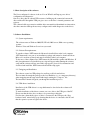
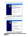
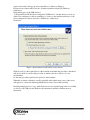
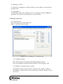
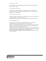
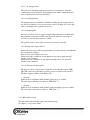
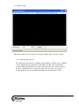
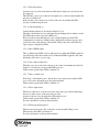
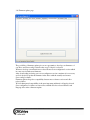
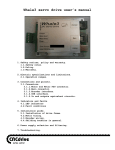
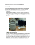
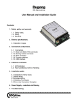
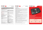
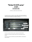
Servoconfigurator3 software user’s guide
Contents
1. Short description of the software.
2. Software Installation.
2.1. Unzipping and Installing.
2.2. USB drivers installation.
2.3. Runing the software
3. Tab pages and screens.
3.1. Connection page.
3.1.1. Language selection.
3.1.2. Number of connected deviced
textbox.
3.1.3. Device listbox.
3.1.4. Check device list button.
3.1.5. Connect to device button.
3.1.6. Aliasing drives to axis.
3.2. PID tuning page.
3.2.1. Downloading and reloading data.
3.2.2. Drive settings / PID parameters
3.2.2.1. Step multiplier
3.2.2.2. Maximum error
3.2.2.3. PWM limit
3.2.2.4. Current limit
3.2.2.5. Ap (Proportional term).
3.2.2.6. Ad (Differential term).
3.2.2.7. Ai (integral term).
3.2.2.8. Li (Integral limit).
3.2.2.9. Sampling time.
3.2.2.10. Step active edge selection
3.2.2.11. Encoder decoding modes.
3.2.3. Mini analiser screen
3.3. Error viewer page.
3.3.1. Topmost window function
3.3.2. Scaling the error graph.
3.4. Analisator page.
3.4.1. Analising step response.
3.5. Diagnostics page.
3.5.1. LEDs / indicators.
3.5.1.1. USB connection ready.
3.5.1.2. Running/fault indicator.
3.5.1.3. Encoder detected.
3.5.1.4. Current limiting on.
3.5.1.5. Motor PWM output.
3.5.1.6. Servo limit reached error.
3.5.1.7. Drive overheat error.
3.5.1.8. Error output active.
3.5.1.9. Error/stop input triggered.
3.5.2. Digital readouts (DRO).
3.5.2.1. Position machine DRO.
3.5.2.2. Position commanded DRO.
3.5.2.3. Servo error DRO.
3.5.3. Steps per input field.
3.5.4. Device reset function.
3.6. Firmware update page.
3.6.1. Updating firmware.
3.6.1.1. What to do if a firmware
update fails.
3.7. Visit website page.
3.8. Help page.
1. Short description of the software.
The Servoconfigurator3 software is the tool for our Whale3 and Dugong servo drives’
configuration and diagnostics.
Our servo drives has an onboard USB connector, building up the connection between the
drive and host PC through the USB port gives access to the drive’s internal parameters and
registers.
The software builds up connection with the drives automaticly with minimal user interaction,
after the connection built up the user may configure and/or make diagnostics on the drives.
2. Software Installation.
2.1. System requirements.
The software runs on Windows 2000, XP, XP x64, 2003 server, 2008 server operating
systems.
Windows Vista and Windows Seven is not yet tested.
2.2. Software Prerequirements.
To run the software .NET framework 2.0 must be installed first on the local computer.
.NET framework is not part of our installation package and it must be downloaded from
Microsoft’s website separately and must be installed on the local computer.
Today most of the computers has .NET framework 2.0 installed together with Windows. If
this prerequirement is not installed an error sign will appear when running the software
setup and the software will not start. If this sign appears, please follow instructions and
download and install the .NET framework and run the setup again.
2.3. Unzipping and Installation.
The software comes in a ZIP package for smallest possible download size.
The user must first unzip the package to the local harddrive (e.g. to a temporary directory).
After unzipping run the setup wizard with simply starting the „setup.exe” file.
The installation wizard will guide you through the installation process.
2.4. USB drivers installation.
Installation of the USB drivers is a step which must be done before the software will
function well.
To make installation of the drivers connect one servo drive to the USB port of the PC.
Please note that the drive does not have to be powered up at this time.
For first time, when the first piece of drive is connected to the USB port, the „New
hardwae found” wizard will pop up showing that the device is connected to the PC and
that the operation system recognises the device.
Windows will ask if it may try to find drivers for the new device on Windows update site.
Check „No, not this time” and press next as shown on Figure 1. below. Press next button.
Figure 1. New hardware found wizard, no auto installation.
After clicking next a new window will pop up.
On this screen select „Install from a list or specific location (Advanced)” as shown on
Figure 2. below. Press next button.
Figure 2. New hardware found wizard, Install from harddrive location.
Again a new window will pop up and set checkboxes as Shown on Figure 3.
Press the browse button and browse the „Software installation directory/USB drivers”
subdirectory.
In default the place of the USB drivers is
„C:\Program Files\CNCdrive\Servoconfigurator3\USB drivers”, but this directory can be set
at the Servoconfigurator3 software installation, so browse to the installation directory of the
Servoconfigurator3 software and select „USB drivers” subdirectory.
Click Next.
Figure 3. New hardware found wizard, browse drivers.
Windows will copy the required files for the installation and when the procedure is finished it
will ask for driver association, this procedure is similar to the above listed, so it is not
described here.
Do the same procedure again listed in point 2.4. in this manual.
When this procedure is finished, a small popup bulb in the right-bottom corner of the screen
will appear for a short time indicating that the drivers where successfully installed.
Installing multiply devices is easy. After the first device was installed plug in the second, third
etc. drives to the USB port and Windows will automaticly intall these without any user
interactions.
2.5. Runing the software
To run the Servoconfigurator3 software click the icon on the desktop or run it from the
Programs menu.
2.6. Uninstallation.
To uninstall the software run „unintall.bat” file or use Windows software Add/Remove
application, this will remove the application from your harddrive.
3. Tab pages and screens.
3.1. Connection page.
This is the startup screen of the application.
Figure 4. shows the connection page.
Figure 4. Servoconfigurator3 - Connection page
3.1.1. Language selection.
The software supports few languages like English, Hungarian, Polish.
Select your language from the dropdownlist under the „Select language” label.
3.1.2. Number of connected deviced - textbox.
On startup the software detects the drives connected to the computer’s USB port.
The number of connected devices shown in the textbox under the „Number of drives
found” label.
3.1.3. Devices - listbox.
All detected drives’ serial numbers appears in the listbox under „Selectable devices
connected to PC” textbox.
3.1.4. Check device list - button.
If new devices connected after software startup they can be listed with pressing
„Check device list” button. This will re-check the USB port for new drives and will
update the list of serial numbers.
3.1.5. Connect to device - button.
To make connection to a drive click on it’s serial number (or alias name) in the listbox
to select it and press „Connect to device button”.
With this interaction the connection between the software and the drive is built up.
3.1.6. Aliasing drives to axis.
Serial numbers may be hard to keep in mind and therefor it can be difficult to
remember which drive is used for the machine’s X-axis, Y-axis etc.
Therefor we’ve made a function called „aliasing”, this allows the user to alias a serial
number to an axis name. After aliasing a drive’s serial number, only the alias name
will appear in the listbox instead of the serial number.
To alias a drive select it’s serial number from the drop-down list next to the axis name
you like to alias. Press „Save” button to save this setting, after saving the software will
always show only the alias name in the lisbox even after a restart.
To clear an alias select „no alignment” in the dropdown list next to the axis name you
like to clear the alias.
3.2. PID tuning page.
To tune the drive’s PID controller select the „PID tuning” tab page in the tab control.
3.2.1. Downloading and reloading data.
To donwload new parameters into the drive press the „Download” button.
To load data from the drive’s memory and to show it on the screen press the „Reload”
button.
3.2.2. Drive settings / PID parameters.
To make the drive fit the controlled system, the PID and other parameters must be set
and tuned correctly.
3.2.2.1. Step multiplier.
The drives accepts step and direction signals as control inputs.
When the step multiplier set to 1 (default) one step to the step input makes the
motor to rotate one encoder increment to the direction depends on the direction
signal’s polarity.
For example if the step multiplier is set to 2. the motor will rotate 2 encoder
increments for every step signal.
The step multiplier is useful when the host/control PC or PLC or other controller
equipment’s frequency is limited to a lower value which is needed to run the motor
with the desired maximal speed.
The step multiplier may have a value between 1 and 10.
We advice to use the step multiplier only if there is really a need for it’s use or set
it the lowest possible value.
3.2.2.2. Maximum error.
Servo error means the difference between the set position and the actual/real
position. The „Maximum error” parameter defines the maximum number of steps
in absolute value which is allowed during the movements.
If the servo error groes above the set value the drive stops.
(The indication of the fault is defined in chapter 3.5.1.6.)
3.2.2.3. PWM limit.
PWM means „pulse width modulation”, it is the output Voltage to the motor and it
it has 9 bit resolution, 512 increments.
This parameter can be useful if motor’s power supply’s Voltage is higher than the
motor’s rated voltage. The maximum avarage voltage on the motor terminals can
be calculated with the following formula:
Umotormax = (PWM limit value/512)*power supply voltage
It is better to use a power supply which has the required voltage level, than to limit
the PWM, because limiting the PWM too much may make control performance
poor.
3.2.2.4. Current limit.
Our drives makes cycle-by-cycle current limiting, this means that if the current
grows above the set current limit level, the current will be limited at the set level.
If the set current level is reached and if the motor tries to pull out more current
from the drive than the set value, the drive keeps to current-flow on the set level
and not allows the current to rise above the set value. This technic is also called as
active current limiting.
3.2.2.5. Ap (Proportional term).
This term is for set the system response fast and dynamic.
There’s linear relation between (Ap* position error) and PWM output.
Increasing this value makes the response time shorter but makes the system more
unstable. This term is also known as „gain”.
3.2.2.6. Ad (Differential term).
This term makes the system damped, in other words it helps to accelerate and
deccelerate faster.
There’s linear relation between (Ad*motor’s speed)and PWM output.
Increasing this value makes the stability of the system better and makes the
response time longer. This term is also known as „damping”.
3.2.2.7. Ai (integral term).
This term is for trimming out the following error to 0 and helps to reach the
commanded position accurately. Increasing this value makes settling faster and
more accurate but also increases instability.
3.2.2.8. Li (Integral limit).
The integral term may be limited to elliminate windup near the setpoint, but it is
not adviced to limit it too low, because it may causes following error. Leave this
value to maximum is the optimal in most cases.
3.2.2.9. Sampling time.
Most of servo drives does not support sampling time adjustment, we think, that
this parameter is important and the controller can be tuned for wide range of
servomotors, because this parameter is setable.
The optimal value for most of the servomotors is between 3 and 10.
3.2.2.10. Step active edge selection.
Defines the active edge of the step signal when it is read by the drive and when the
step command is executed.
It can be set to active high or active low.
When active high, a transition on step input from low state to high state will
execute a step command.
When active low, a transition on step input from high state to low state will
execute a step command.
3.2.2.11. Encoder decoding modes.
The basic resolution of an encoder is defined as Counts Per Revolution (CPR).
This CPR value is the full number of pulses per one revolution of the encoder.
The drive supports 2 kinds of decoding modes:
- 2X mode
In this mode all A channels and B channels rising edges are counted.
The total edges counted per revolution is: CPR value * 2.
- 4X mode
In this mode all A channels and B channels rising and falling edges are counted.
The total edges counted per revolution is: CPR value * 4.
3.2.3. Mini analiser screen.
The mini analiser functions the same as the analisator page.
See chapter 3.11. for more details.
3.3. Error viewer page.
The error viewer page is a graph which shows the servo-error.
The graph is continiously refreshing and showing actual values.
With the error viewer user may check and follow the position error made by the system.
3.3.1. Topmost window function.
Checking the „Window always on top” checkbox makes the window appear above
other applications’ windows. This is useful forexample when running the software on
the same PC which generates the motion. (E.g. running Mach3).
Checking this box will make the Servoconfigurator3 appear above Mach3’s screen.
3.3.2. Scaling the error graph.
The error graph is scaled in vertical direction automaticly to the „Max.error” set in the
drive, however the screen can be rescaled to show e.g. smaller errors more easily
readable. To rescale the window write the desired number of steps the window to be
scaled into the textbox next to the label „Scale errorviewer window” and press the
„OK” button.
3.4. Analisator page.
With analyse function user can check step response quality of the control loop tuning.
3.4.1. Analising step response.
By clicking the analyse button, commanded signal change to actual position + number
of steps wrtitten into the textbox next to the button. In other words, commanded
position changes immadiately with a value written into the textbox. In this situation
the drive commands the motor to pick up new position, the servo error signal is
monitored and the response graph drawn graphicaly onto the analisator screen.
3.5. Diagnostics page.
The diagnostics page gives information about vitality of the drive and lets the user see if
any error occured.
3.5.1. LEDs / indicators.
LED indicators are virtual LEDs placed onto the screen, each LED has a meaning,
described below.
3.5.1.1. USB connection ready.
When the USB connection is built-up and when the software is receiving packets
from the drive, this LED is blinking in green color indicating the acive USB
connection.
3.5.1.2. Running/fault indicator.
This LED is bicolor, if the drive is running normal this led has a green color.
If the drive is stopped with an error this LED lights with a red color indicating the
fault and that the drive was stopped.
3.5.1.3. Encoder detected.
Our drives has a special safety function which detects faulty encoder and encoder
disconnection.
This LED has a green color if the encoder inputs has a correct format and when the
encoder is working well.
If the encoder is not connected or if a line of the encoder is faulty this LED
becomes red indicationg the error.
3.5.1.4. Current limiting on.
Current limiting function is described in chapter 3.2.2.4.
When the current limit level is reached the current limiting circuit switches on and
this LED indicates this event with a RED color.
Please note that current limiting may work on high frequency and the USB
communication is made by sending packets, therefor this indicator may not show
exactly the same as the phisical „current limit” LED on the drive, this LED may
lag in respect to the physical LED.
3.5.1.5. Motor PWM output.
This is a bidirectional LED, it shows with green color when the PWM is applied to
one half bridge and it shows with red color when the PWM is applied to the other
half bridge of the drive’s power stage.
3.5.1.6. Servo limit reached error.
When the servo error in absolute value goes above the set maximum (described in
chapter 3.2.2.2) the drive stops and this LED goes red.
Under normal operation this LED is switched off.
3.5.1.7. Drive overheat error.
If the drive’s metal frame gets too hot the drive stops with an error and this LED
goes red. For more information see the product manuals.
Under normal operation this LED is switched off.
3.5.1.8. Error output active.
When any of the errors occurs the error line of the drive gets activated indicating
the error to other devices connected to the error line. .
Activity of the error line shown by this LED with red color.
Under normal operation this LED is switched off.
For more information see the products manuals.
3.5.1.9. Error/stop input triggered.
When an external error/stop line of the drive is activated this LED goes red.
When inactive this LED is switched off.
For more information see the products manuals.
3.5.2. Digital readouts (DRO).
Digital readouts shows positions and error values in numeric format.
3.5.2.1. Position machine DRO.
This is a signed 32 bit value shows the actual position of the motor/axis, in other
words this is the Commanded position – servo error.
3.5.2.2. Position commanded DRO.
This is a signed 32 bit value shows the commanded position of the motor, in other
words it shows the signed sum number of step signals applied to the drive.
3.5.2.3. Servo error DRO.
Servo error is the commanded position – real position of the motor/axis.
In other words this DRO shows the difference from the desired position.
It shows maximum value of +-20000 or a set value of Max.error set in the drive.
3.5.3. Steps per input field.
A numeric decimal value should be written into this textbox.
The values shown by the DROs will be divided with the „steps per” value.
This is useful when the user like to see values forexample in mms or inches.
Forexample if it takes 500steps for the drive to make the axis travel 1mm, then the
value of 500 should be written into the steps per field to see the travel in mm units.
3.5.4. Device reset function.
By pressing the Reset button the connected drive makes a soft reset.
It stops and rebooting and starts operation from the beginning.
On reset all counters are cleared and all parameters read again from the EEPROM.
3.6. Firmware update page.
The possibility of firmware update gives us an opportunity to develope our firmwares of
our drives and Servoconfig3 software after a type of device is released.
When we develope a new function we release the new Servoconfigurator3 version which
in some cases includes new firmwares.
After downloading and using a new servoconfigurator version sometimes it is nessessary
and it is adviced to update the firmware in the drives with the actually used newest
Servoconfig3 software.
Firmware updates keeps the compatibility between new software versions and older
released drives.
We feel that upward compatibility is the most important and therefor all newly released
Servoconfigurator3 software versiona will work with all before released Whale3 and
Dugong drives after a firmware update.
3.6.1. Updating firmware.
To update the firmware of a drive select the „Firmware update” tab page and press the
„Update firmware in drive” button.
A warning will pop up and to proceed with the update press ’Yes’.
At that point firmware update starts.
Please note that it may take several seconds for the update to finish.
Wait until the process is finished and the „Firmware update successful” message
appears on the page.
For the firmware update the drive’s digital power must be on and powered.
Do not unpower the drive when the firmware update is in progress, if you do the
firmware update process will fail and it will be indicated with a „Firmware update
failed” message.
3.6.1.1. What to do when a firmware update fails.
There can be cases when the firmware update fails.
If this happens the download of the new firmware is incomplete.
In this case the firmware update must be repeated.
In some cases there is a need for special threatment when firmware update, an
example is an update of the Dugong drives from Servoconfig R3.12 to R3.14
version.
Because the Baudrate of the communication was changed in this example update,
the older released Dugong drives will be unable to communicate with the new
R3.14 software.
To update the firmware in this and some other special cases follow the steps
below.
The same threatment is sometimes nessessary after a firmware update failure.
If the drive does not startup after a firmware update try the following procedure
below.
Please note that a failed firmware update cannot make the drive to fail and the
firmware update can be repeated any time to bring a drive „back to life” after a
failed firmware update process.
Steps to make after an unsuccessful firmware update:
1.) Switch off the drive’s digital power.
2.) Run Servoconfig3 software and select the Firmware update TAB page.
3.) Click „Update firmware in drive” button.
Note: A window will pop up, but do not press Yes or No yet.
4.) Switch on the drive’s digital power and before 1 second ellapses press ’Yes’
button in the before poped-up window.
Description of the above steps:
On powerup the drive jumps first into „Boot-mode” and waits for USB packets
from the PC which contains a firmware, this waiting time is 1seconds.
If no USB packet comes with new firmware in this time interval, the drive will
start executing current firmware loaded into the drive.
If the current firmware is broken (e.g. due to interupted firmware update process)
then the firmware will not be executed and the drive will not starup and will wait
for new firmware data for an infinate time. In this case a new firmware can be
downloaded any time.
3.7. Visit website page.
This page contains links to our website and links for e-mail sending.
3.8. Help page.
Software and hardware manuals can be opened from this page.
Caution:
Please note that this document is under development and may contains
minor bugs and mistypes.
For new device and software intallations please download and use to
the latest version of this documentation.
For more information please visit:
Website: http://www.cncdrive.com
E-mail: [email protected]