1
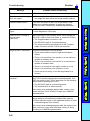
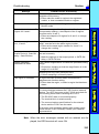
SECTION 9
Troubleshooting
This section lists the errors that may occur during F150-2 operation, along with their probable causes and remedies.
243
Section
Troubleshooting
Message
9
Probable Cause and Remedy
Camera is not connected.*
• The Camera Cable is not connected properly.
Cannot measure the angle
from one region.
• Select a region for which binary center of gravity and
axis angle has been set as the measurement method.
Communications error.*
Turn OFF the power to the F150-2 and restart. If the
same error message appears, it may mean that the
F150-2 is faulty. Contact your OMRON representative.
Draw at least one OR
figure.
NOT mode is used to delete part of a drawn diagram.
Host link error. Change to
normal mode.
(see note)
After checking for the following items, either change the
RS-232C mode to Host Link mode, or restart the F150-2:
• Draw diagrams in OR mode.
• The Programmable Controller is ON.
• The RS-232C cable is connected properly.
• The communications specifications for the Programmable Controller and the F150-2 are the same.
Illegal syntax in expression.
Check the following for the expression:
• There are the same number of right and left parentheses.
• There is not more than one operator in a row without a
variable in between them.
• There is not more than one function in a row without a
variable in between them.
• There is not more than one region number in a row.
• There is not more than one constant in a row.
• There are not too many, or too few arguments for a
function.
Incorrect data format
received.*
There is a mistake in the data for which transfer between
the F150-2 and the external device was attempted. Turn
OFF the power to the F150-2, and check for the following
items before restarting the F150-2.
• The RS-232C cable is connected properly.
• The terminal block is wired correctly.
If the same error message appears after restart, it may
mean that the F150-2 is faulty. Contact your OMRON
representative.
Insufficient flash memory.
An error has occurred in flash memory. Data cannot be
saved because of insufficient available flash memory.
• Either make the region to be registered smaller, or clear
unneeded regions from memory.
If the same error message appears after the regions have
been reduced, it may mean that flash memory is faulty.
Contact your OMRON representative.
244
Section
Troubleshooting
Message
Insufficient work memory.
9
Probable Cause and Remedy
No more regions can be registered because of insufficient
available work memory.
• Either make the model or region to be registered
smaller, or clear unneeded models or regions.
PC is not in monitor mode.*
• Change the mode of the Programmable Controller to
Monitor mode.
Select midpoint between 2
regions for X and Y.
If the relative angle of the 2 regions is set for the position
compensation setting θ, the midpoint of the 2 regions
must be set for X and Y.
• Either set midpoint of 2 regions for X and Y, or change
the θ setting.
Select same region number
for θ, X and Y.
If position compensation region 0 or 1 is set for θ, then X
and Y must be set to the same region number.
• Either set the same region number for X and Y, or
change the θ setting.
Set parameters so that
Output Period y Gate ON
delay + Gate ON time.
The communications specifications for the terminal block
are set incorrectly.
Setting calibration
parameters is failed.
The Camera magnification is outside the permitted setting
range.
• Make the settings so that output period y GATE ON
delay + GATE ON time.
• Re-perform sampling so that the magnification is in the
range 0.01 to 9.999.
Sampling has only been performed once.
• Perform sampling in at least 2 places.
This region is not drawn.
A region that has not been drawn is selected as a
displacement direction setting.
• Either draw the region, or select a region that has been
drawn.
Timeout error.*
Data transfer has been interrupted due to a timeout error
in communications between the F150-2 and an external
device. Turn OFF the power to the F150-2, and check for
the following items before restarting the F150-2.
• The RS-232C cable is connected properly.
• The terminal block is wired correctly.
• The communications specifications for the external
device and the F150-2 are the same.
If the same error message appears after restart, it may
mean that the F150-2 is faulty. Contact your OMRON
representative.
Note When the error messages marked with an asterisk are displayed, the ERR terminal will come ON.
245