1
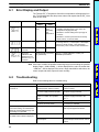
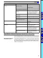
SECTION 6
Troubleshooting
This section describes the troubleshooting of the Thermac E5jJ Temperature Controller.
6-1
6-2
Error Display and Output . . . . . . . . . . . . . . . . . . . . . . . . . . . . . . . . . . . . . . . . . . . . . . . . . . .
Troubleshooting . . . . . . . . . . . . . . . . . . . . . . . . . . . . . . . . . . . . . . . . . . . . . . . . . . . . . . . . . .
44
44
43
Troubleshooting
6-1
Section 6-2
Error Display and Output
The Thermac E5jJ Temperature Controller incorporates a self-diagnostic function. The following table lists the process values and outputs that the E5jJ has
when errors result.
PV display
Error
Output
Control
output
Abnormal input
OFF (2 mA
max.)
Items to be checked
Alarm
output
Processed
as an
abnormally
high
temperature.
• Whether or not the input has exceeded the
possible controlling range (±10% of the set
temperature range) (see note).
• Whether or not the setting of the input type is
incorrect.
• Whether or not the input has been incorrectly
wired, broken, or short-circuited.
Abnormal memory OFF (2 mA
max.)
OFF
Abnormal A/D
converter
OFF (2 mA
max.)
OFF
Abnormal
calibration data.
Displayed for 2 s
when the E5jJ is
turned on.
Normal operation (accuracy
not guaranteed)
Turn the E5jJ OFF and ON. If the display does
not change, the E5jJ need repairs. If the display
returns to normal, the E5jJ may have been
influenced by noise. Check for noise interference.
The E5jJ needs calibration. Contact your
OMRON representative.
Note If the input is within the possible controlling range but exceeding the possible
display range (–1999 to 9999), (((( will be displayed if the value is smaller than
–1999 and )))) will be displayed if the value is larger than 9999, at which time, the
control output and alarm output will work normally.
6-2
Troubleshooting
Refer to the following table for troubleshooting.
Phenomenon
Nothing is displayed when the E5jJ
is turned on.
No setting is possible.
Probable cause
Properly insert the internal mechanism
into the housing.
The power supply is not connected to
the power supply terminals properly.
Properly connect the power supply to
the power supply terminals.
No power is supplied or the supplied
power is not within the specified
range.
Supply a voltage of 85 to 264 VAC to
the power supply terminals of the
E5jJ.
The key protection switch is set to ON. Set the key protection switch to OFF.
The E5jJ with a communications
function is in remote mode.
When the Up Key is pressed for set
The set point limit function is active.
point value setting, the value flashes
within the set temperature range and
the setting is not possible.
No alarm, heater current value display, The alarm mode switch is set to 0.
or heater burnout alarm is displayed.
A Current Output Unit is used for
control output.
44
Countermeasure
The internal mechanism is not
inserted properly into the housing.
The E5jJ must be in local mode or
no front key is available.
Properly set the set point lower limit
and set point upper limit values.
Select the proper alarm mode.
No heater burnout is detected if the
Current Output Unit is used for control
output.
Troubleshooting
Section 6-2
Phenomenon
Probable cause
The process value is abnormal or not
obtained.
No control output is obtained.
The heater burnout detecting function
is abnormal.
Countermeasure
The input polarity is wrong or the
connection is wrong.
Properly wire the terminals.
The input-type setting is incorrect.
Properly set the input with the
input-type selector.
No compensating lead wires are used
for the extension of the thermocouple.
Use proper compensating lead wires.
The thermocouple and E5jJ is
connected via wires other than proper
lead wires.
Use a dedicated thermocouple
connector. If a metal material different
from the thermocouple is used to
connect the thermocouple and E5jJ,
a temperature error may result.
The sensor is broken or
short-circuited.
Use a good sensor.
The E5jJ is influenced by noise or
other induction.
Separate the input wires as far as
possible from the origin of the noise.
°C is used instead of °F or vice versa.
Use the proper temperature unit.
The process value is shifted because
the input shift function is used.
Set the input shift value to 0.
No Control Output Unit is connected.
Connect a Control Output Unit (sold
separately).
Event input 2 of the E5jJ is set to
STOP.
Open event input 2 and set the E5jJ
to RUN.
No Current Transformer (CT) is used.
Properly connect the dedicated
E54-CT1 or E54-CT3 (sold
separately) to the E5jJ.
The heater burnout alarm value is not
proper.
Set the proper heater burnout alarm
value taking into consideration the
fluctuation of the heater supply
voltage and measurement error.
Use the control output. Heater burnout
detection synchronizes with the
control output. Any other output
cannot be used.
The heater is turned ON or OFF with
an output other than the control
output.
Simple Method to Determine Temperature Controller Error or Sensor Error
When Thermocouple is Used If the temperature displayed by the E5jJ is close to the room temperature when
the input terminals of the E5jJ is short-circuited, the E5jJ deemed to be normal
and it is presumed that the sensor is broken, short-circuited, or incorrectly wired.
When Platinum Resistance
Thermometer is Used
If the temperature displayed by the E5jJ is close to 0.0°C when a resistor with a
resistance of approximately 100 Ω is inserted between terminals A and –B of the
E5jJ and terminals +B and –B of the E5jJ are short-circuited, the E5jJ
deemed to be normal and it is presumed that the sensor is broken, short-circuited, or incorrectly wired.
45