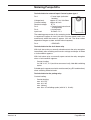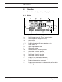
1
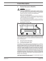
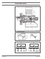
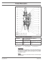
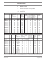
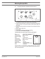
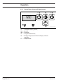
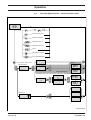
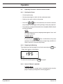
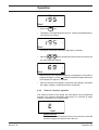
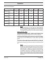
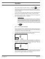
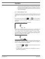
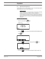
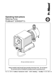
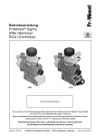
® Operating Instructions ProMinent® Sigma SIBa (Basic Type) SICa (Control Type) SIBa SICa Affix type identification plate here! Two sets of operating instructions are necessary to ensure the ProMinent® Sigma SIBa or SICa metering pumps are operated safely and reliably for their intended purpose: These product-specific Sigma operating instructions and the operating instructions for ProMinent® motor-driven metering pumps; both are only applicable in conjunction with each other! Please completely read through these operating instructions first! • Do not discard! The warranty shall be invalidated by damage caused by operating errors! Version Part No. 1.0 987747 ProMinent Dosiertechnik GmbH • D-69123 Heidelberg • Germany Page 1 of GB 44 BA SI 008 08/00 Imprint: Operating Instructions for ProMinent® Sigma SIBa/SICa ProMinent Dosiertechnik GmbH, 1995 ProMinent Dosiertechnik GmbH Im Schuhmachergewann 5-11 D-69123 Heidelberg P.O. Box 101760 D-69007 Heidelberg [email protected] www.prominent.de Subject to technical modifications Type setting/DTP: Bartha Docuteam GmbH D-64625 Bensheim Issue 08/00, Version 1.0 Printed in the F.R. Germany Contents Page Device Identification/Identity Code ....................................................................................................... 2 Device Identification/Identity Code ....................................................................................................... 3 1. Notes on Safety of ProMinent® Metering Pumps ......................................................................... 4 1.1 General Notes ....................................................................................................................4 1.2 Notes on Installation, Start-Up and Operation ................................................................... 4 1.3 Notes on Maintenance and Repair .....................................................................................6 2. Product Description SIBa/SICa ...................................................................................................7 2.1 Identification of Pump Type ................................................................................................7 2.2 Design/Functional Description............................................................................................ 7 2.2.1 Functional Description, Drive .................................................................................... 7 2.2.2 Stroke Movement ......................................................................................................8 2.2.3 Metering Capacity Diagram ...................................................................................... 9 2.2.4 Functional Description, Delivery Unit: .....................................................................11 2.2.5 Integrated Overflow Valve with Bleeder Function ...................................................12 2.2.6 Diaphragm Failure Monitor ......................................................................................15 3. Technical Data ...........................................................................................................................17 3.1 Technical Data Sigma Basic Type SIBa ..........................................................................17 3.1.1 Capacity Data ..........................................................................................................17 3.1.2 Table for Measuring from SIBa and SIBa with Setting Motor .................................18 3.1.3 Dimensions SIBa .....................................................................................................19 3.1.4 Dimensions SIBa with Actuator ...............................................................................19 3.1.5 Motor Data ..............................................................................................................20 3.1.6 Electrical data, stroke sensor "SIBa" ......................................................................20 3.1.7 Electrical data, pacing relay "SIBa" .........................................................................20 4. Start-Up/Maintenance ................................................................................................................20 4.1 Start-Up ............................................................................................................................20 4.2 Maintenance .....................................................................................................................20 4.3 Replacement of Wearing Parts ........................................................................................21 5. Special Features of the SICa metering Pump ...........................................................................23 5.1 Functional Description of the Motor .................................................................................23 5.2 Functional Description of the Drive ..................................................................................23 5,3 Plug Strip Connector, Symbols and Connections ............................................................24 6 Operation ...................................................................................................................................27 6.1 Explanation of the Operating and Display Elements ........................................................27 6.1.1 Display ....................................................................................................................27 6.1.2 Control Panel: Keys and Display Lamps.................................................................28 6.2 Overview Operating Plan - Control Version 0 and 1 ........................................................29 6.3 Operating Functions - Control Versions 0 and 1 ..............................................................30 6.3.1 Starting the Pump ...................................................................................................30 6.3.2 Stopping the Metering .............................................................................................30 6.3.3 Internal "Manual" operation .....................................................................................30 6.3.4 "External "Contact" operation ..................................................................................31 6.3.5 Connecting a Float Switch ......................................................................................36 6.3.6 External ON/OFF (control function "Pause")...........................................................37 6.3.7 Metering Monitor "Flow" ..........................................................................................38 6.3.8 Selection of the Display Functions "f", "N÷" or "N": ................................................39 6.3.9 Error Messages - Acknowledging Error Messages ................................................. 40 6.4 Operation Analog Control .................................................................................................41 7. Tests Sigma SIBa/SICa Device Identification/Identity Code Identity Code Ordering System The device label attached to the title page is identical to that on the pump to facilitate matching the correct operating instructions to the pump. Please enter the identity code on the device label into the grey box below. SIBa S i g m a B a s i c Ty p e , ( S I B a ) HM Main drive, diaphragm Pump type: (figures 1- 3 = back pressure [bar], figures 4 + 5 = feed rate [l/h] 12050* 12090* 12130* 07120 07220 04350 * for PVDF versions, max. 10 bar PV SS Liquid end materials: PVDF stainless steel T Seal material: PTFE seal 0 1 Diaphragm: standard diaphragm, PTFE version with diaphragm rupture indicator (retro fit possible) 0 1 4 5 Liquid end version: no spring with 2 valve springs, Hastelloy C4 0.1 bar with pressure relief valve, Viton seal, no valve spring with pressure relief valve, Viton seal, no valve spring 0 1 2 3 4 5 6 Hydraulic connection: standard according to technical data union nut and PVC insert union nut and PP insert union nut and PVDF insert union nut and stainless steel insert union nut and PVDF hose sleeve union nut and stainless steel hose sleeve 0 1 Version: with ProMinent® label (standard) without ProMinent® label (standard) S M N L P R Z 1 2 3 Electrical power supply: 3 ph, 230 V/400 V 50/60 Hz, 0,18 kW 1 ph AC, 230 V/50/60 Hz, 0,18 kW 1 ph AC, 115 V/60Hz, 0,25 kW 3 ph, 230 V/400 V, 50Hz, (EExe, EExde) 3 ph, 230 V/400 V, 60Hz, (EExe, EExde) 3 ph, variable speed motor, 230 V/400 1 ph, variable speed, 230 V, 50/60 Hz no motor, with B14 flange (Gr. 71 (DIN)) no motor, C 56 flange (NEMA) no motor, B5, Gr. 63 (DN) 0 1 2 Enclosure rating: IP 55 (standard) Exe version (EExe II T4) Exde version (EExde IIC T4) 0 2 3 Stroke sensor: no stroke sensor (standard) pacing relay (reed relay) stroke sensor (Namur) for hazardous locations) 0 1 2 3 4 5 6 Stroke length adjustment: manual (standard) with stroke positioning motor, 230V/50/60Hz with stroke positioning motor, 115V/50/60Hz with stroke control motor, 0...20 mA 230V/50/60Hz with stroke control motor 4 ... 20 mA 230V/50/60Hz with stroke control motor 0 ... 20 mA 115V/50/60Hz with stroke control motor 4 ... 20 mA 115V/50/60Hz SIBa Page 2 of 44 Version 1.0 Device Identification/Identity Code Identity Code Ordering System The device label attached to the title page is identical to that pump to facilitate matching the correct operating instructions to the pump. Please enter the identity code on the device label into the grey box below. SICa S i g m a C o n t r o l Ty p e , ( S I C a ) HM main displacement component, diaphragm Pump type: (figures 1 - 3 = back pressure [bar], figures 4 + 5 = feed rate [l/h]) 12050* 12090* 12130* 07120 07220 04350 * = for PVDF versions, max. 10 bar PV SS Liquid end materials: PVDF stainless steel T Seal Material: PTFE seal 0 1 2 Diaphragm: standard diaphragm, PTFE version with diaph. rupture indicator (may be retrofitted) with "pump stopping" function with diaph. rupture indicator (may be retrofitted) with "pump alarm" function continues to operate 0 1 4 5 Liquid end version: no spring with 2 valve springs, Hastelloy C4, 0.1 bar with pressure relief valve, Viton seal, no valve spring with pressure relief valve, Viton seal, and valve spring 0 1 2 3 4 5 6 Hydraulic connection: standard according to technical data union nut and PVC insert union nut and PP insert union nut and PVDF insert union nut and stainless steel insert union nut and PVDF hose sleeve union nut and stainless steel hose sleeve 0 1 Version: with ProMinent® label (standard) without ProMinent® label (standard) A B C D E F G H I Electrical power suppley: 1 ph. 230 V, 50 Hz, Euro plug 1 ph. 230 V, 50 Hz, Swiss plug 1 ph. 230 V, 50 Hz, Austral. plug 1 ph. 115 V, 60 Hz, USA plug 1 ph. 100 V, 50 Hz, Japanese plug 1 ph. 100 V, 60 Hz, Japanese plug 1 ph. 200 V, 50 Hz, open cable 1 ph. 200 V, 60 Hz, open cable 1 ph. 230 V, 60 Hz, Euro plug 0 1 Control type: manual + contact manual + contact + analogue 0 1 2 3 Relay swiss mode: no relay (standard) with fault indicating relay (N/C) with pacing relay (N/O) with fault indicating relay (N/O) 0 Stroke Length Adjustment: manual SICa Version 1.0 Page 3 of 44 Notes on Safety of ProMinent® Metering Pumps 1. Notes on Safety of ProMinent® Metering Pumps Notes on safety and important operating notes are divided into classes accompanied with pictograms. Please familiarize yourself with the following definitions and pictograms. DANGER: Danger to life or risk of serious injury! WARNING: Danger of injury or serious damage to the device! ATTENTION: These situations require complete attention! NOTE: Information which must be followed! 1.1 General Notes WARNING: • The equipment/devices may only be used for their intended purpose. • ProMinent® metering pumps must not be assembled with parts which are not tested and recommended by ProMinent otherwise this can lead to injury to persons and damage to property for which no liability will be accepted! • Pumps must be accessible at all times to facilitate operation and maintenance. Access points must not be obstructed or blocked! • Before carrying out any maintenance and repair work always drain off and flush out the liquid end first if hazardous or unknown metered media are used! Observe safety data sheets of metered liquids! • When metering hazardous or unknown liquids, always wear safety clothing (safety goggles, gloves) when working on the liquid end! 1.2 Notes on Installation, Start-Up and Operation WARNING: • The metering pump can contain water residue in the liquid end as the result of testing at the factory! • If handling media which must not come in contact with water, all traces of water must be removed from the liquid Page 4 of 44 Version 1.0 Notes on Safety of ProMinent® Metering Pumps end before start-up! For this purpose, turn the pump through 180˚ and drain off the liquid end then flush with a suitable medium from above via the intake connection! • Do not connect mains voltage to the control cable! • When operating the metering pump against a closed shut-off element on the delivery side, the backpressure produced by the pump can reach multiple of the maximum permissible backpressure! This can cause the delivery line to burst! • To avoid this, an overflow valve which limits the maximum permissible backpressure is recommended! ATTENTION: • Arrange delivery lines such that pressure peaks during the metering stroke do not exceed the maximum permissible operating pressure (install an overflow valve if necessary!) • Set stroke length only with pump in operation! • Pull the red plug for venting the gear unit during initial operation of the Sigma metering pump (refer to Fig. 005-D Item 10)! NOTE: • The pump must be secured in such a way that no vibrations can occur! The valves of the liquid end must always be positioned vertically in order to ensure trouble-free operation! • The intake and delivery lines must always be arranged such as to ensure connection at the liquid end free of mechanical stress! The lines must be secured such that no vibrations can occur! • Only use the clamping rings and hose sockets intended for the relevant hose diameter as well as original hoses with the specified hose dimensions and wall thickness otherwise the stability and durability of the connection will not be guaranteed! Avoid reducing hose sizes! Observe the permissible pressure of the hoses! Version 1.0 • A vent with return to the supply tank is advisable when metering extremely aggressive or hazardous media! • In addition, a shut-off valve should be provided on the delivery or intake side! Page 5 of 44 Notes on Safety of ProMinent® Metering Pumps 1.3 Notes on Maintenance and Repair WARNING: • Only specially trained and authorized persons are permitted to carry out maintenance on metering pumps and their periphery! • If hazardous or unknown metering media are used, always flush out the liquid end first before carrying out any maintenance and repair work! • When metering hazardous or unknown liquids, always wear safety clothing (safety goggles, gloves) when working on the liquid end! • Always depressurize the delivery line first before carrying out any work on the pump! Always discharge and flush liquid end! Observe safety data sheets for metered liquid! DANGER: • Disconnect power plug or power supply line before opening the plug! Isolate relay option if applicable! Check to ensure power is disconnected! Secure pump while carrying out repairs to ensure it cannot be switched on unintentionally! • Pumps for metering radioactive media must not be shipped through standard channels! NOTE: The metering pump must be in a cleaned condition with the liquid end flushed if returned for repair! Page 6 of 44 Version 1.0 Product Description 2. Product Description SIBa/SICa WARNING: Use for intended purpose The pump is designed as a liquid medium metering pump; it serves the purpose of metering liquid medium within the specified line system! General restrictions with regard to viscosity limits, chemical resistance and density must be observed! Use not for intended purpose The pump is not designed for metering gaseous chemicals or suspended solids. See also resistance list no. 2264-4! All other uses or modifications are prohibited. Do not operate outside the ambient conditions described in section 3. The pump must be operated by appropriately trained and authorised personnel. 2.1 Identification of Pump Type SIBa/SICa-004-D The identity code and serial number are given in addition to the standard technical specifications. These two numbers must always be quoted when making any enquiries as they enable distinct identification of the type of metering pump. 2.2 Design/Functional Description 2.2.1 Functional Description, Drive The ProMinent® Sigma diaphragm-type metering pump is an oscillatory displacement pump with the stroke length adjustable in steps of 1%. It is driven by electric motor (1). The rotary drive of the electric motor is stepped down by worm gear (2) and transmitted via the eccentric roller (3) to the push rod (4) connected to fork (8) and converted into oscillatory movement. Return spring (5) presses the fork with push rod positively against the eccentric roller thus producing the return stroke. The stroke is adjusted by means of stroke adjustment knob (6) and spindle (7) by limiting the return stroke. Stroke movement is transmitted directly to the displacement diaphragm. Interacting with the valves, this diaphragm produces the overpressure and vacuum in the liquid end necessary for delivery. Flow is pulsating. In the basic type, the electric motor is normally a 3-ph extended-range AC motor (refer to Section 3 for other options). Version 1.0 Page 7 of 44 Product Description SIBa/SICa-005-D 2.2.2 Stroke Movement SIBa/SICa-006-D Set stroke length dependent on the required delivery capacity. 75% 0 50 25 75 20 30% 0 0 25 5 0 5 10 SIBa/SICa-007-D Page 8 of 44 Version 1.0 Product Description NOTE: A large stroke length and low metering frequency should be selected for very viscous media! A shorter stroke length and high frequency should be selected to achieve good mixing properties! 2.2.3 Metering Capacity Diagram SIBa/SICa HM12090 SIBa/SICa HM12050 Q (l/h) SIBa/SICa HM12130 Pressure in (bar) SIBa/SICa HM12090 SIBa/SICa HM12050 Q (l/h) SIBa/SICa HM12130 SIBa/SICa-015-D Stroke length in (%) Version 1.0 SIBa/SICa-016-D Page 9 of 44 Product Description SIBa/SICa HM07220 SIBa/SICa HM07120 Q (l/h) SIBa/SICa HM04350 Pressure in (bar) SIBa/SICa HM07220 SIBa/SICa HM07120 Q (l/h) SIBa/SICa HM04350 SIBa/SICa-017-D Stroke length in (%) Page 10 of 44 SIBa/SICa-018-D Version 1.0 Product Description 2.2.4 Functional Description, Delivery Unit: The heart of the delivery unit is the DEVELOPAN® metering diaphragm (2). It hermetically seals the delivery chamber of liquid end (4) and produces a displacement in the liquid end. The end disc (5) made of chemically resistant plastic together with safety diaphragm (13) separates the drive housing from the delivery unit and protects the drive from corrosion in the event of the diaphragm failing. Delivery is based on the interaction between intake valve (1) and head valve (3) of the same design together with the diaphragm movement. The valve balls can be supported with springs for metering viscous media. The connection dimensions of valves and liquid ends of the same size but with different materials are identical. These parts can be interchanged as required. Materials and dimensions are specified in Section 3, Technical Data. SIBa/SICa-008-D Version 1.0 Page 11 of 44 Product Description 2.2.5 Integrated Overflow Valve with Bleeder Function Task: The task of the overflow valve is to protect the motor and gear unit against impermissible overpressure caused by the metering pump. This function is produced by a spring-loaded ball. A pressure relief mechanism for the bleeder function is provided. Design and Functional Description (refer to drawing No. 3160-4, 3161-4) Initially, the overflow valve illustrated under Item 102 operates as a simple directly control safety valve. As soon as the pressure set with spring Item 132 is exceeded, the effective pressure raises ball Item 130. The liquid then flows off into the tank via hose connection Item 128. Delivery unit overflow valve Sigma 10 bar PVT * Colour of cap - grey Delivery unit overflow valve Sigma 4 bar PVT * Colour of cap - red Delivery unit overflow valve Sigma 7 bar PVT * Colour of cap - black Identity code type: 12050, 12090, 12130 Identity code type: 04350 Identity code type: 07120, 07220 SIBa/SICa-009-D Page 12 of 44 Version 1.0 Product Description Delivery unit overflow valve Sigma 12 bar SST * Colour of cap - grey Delivery unit overflow valve Sigma 4 bar SST * Colour of cap - red Delivery unit overflow valve Sigma 7 bar SST * Colour of cap - black Identity code type: 12050, 12090, 12130 Identity code type: 04350 Identity code type: 07120, 07220 SIBa/SICa-010-D ATTENTION: • Knob Item 139 must be turned in clockwise direction as far as it will go „close“. • The bypass line must always be closed and must be routed back into the supply tank. Connection via hose connection Item 128. • Minimal overflow can occur in the bypass line when the valve operates close to the overpressure function. The bleeder function is achieved by turning knob Item 139 in counterclockwise direction as far as it will go „open“: Priming aid for starting up pump against pressure. The force of spring Item 132 relieves ball Item 130 which is controlled by the lower spring force of bleeder spring Item 133. ATTENTION: Once the pump has primed, turn knob Item 139 in clockwise direction as far as it will go „close“! The pump can now be placed into operation. Version 1.0 Page 13 of 44 Product Description Technical data Corresponding to the type of pump, overflow valves are available for pressure stages pnom 4, 7, 10 and 12 bar with (1.05 ... 1.15) xpnom opening pressure. Material in contact with metered medium Liqiud end: Overflow valve: Seals in overflow valve: Balls: Springs: PVDF PVDF Viton O-rings,PTFE Ceramic Hastelloy C4 Stainless steel 1.4571 Stainless steel 1.4571 Viton O-rings,PTFE Ceramic Hastelloy C4 Use for intended purpose/Use not for intended purpose Use for intended purpose To protect the motor and gear unit against impermissible overpressure caused by the metering pump. If the pump is the only pressure generator in the system, the overflow valve will also protect the system automatically. ATTENTION: • • • On pumps with a 1 ph AC motor, the motor is protected by an integrated thermal cutout. The ceramic ball and ball seat of the overflow valve are wearing parts. Slight leakage can occur at the safety valve after a prolonged period of operation. The ball and ball seat should be replaced if leaks occur. The bypass line must always be connected and must be routed back into the supply tank. Use not for intended purpose To protect the system from impermissible overpressure which has other causes than the pressure generated by the metering pump. The pump must not be operated without the bypass line connected. The bypass line must not be connected in the intake line (the bleeder function will no longer be guaranteed). The bypass line must be routed back into the supply tank. DANGER: When carrying out maintenance work on the overcurrent valve, pay attention to the tensioning state of the pressure spring Item132! Wear safety goggles! Page 14 of 44 Version 1.0 Product Description 2.2.6 Diaphragm Failure Monitor Task: Monitoring the working diaphragm for leaks. Even after diaphragm failure, this liquid end can continue operation without leaks at full operating pressure in emergency mode until the diaphragm is changed. Design and functional description (refer to drawing No. 3162-4) The „Sigma“ delivery unit with diaphragm failure monitor features consists of the standard liquid end Item 100, the working diaphragm Item 200 and auxiliary diaphragm Item 148 which is arranged between the end disc Item 201 and the intermediate disc Item 147 and forms a sealed intermediate chamber with the working diaphragm Item 200. The working diaphragm Item 200 is monitored for leaks by a diaphragm failure monitor Item 104 which triggers an electrical signal in the event of diaphragm failure thus stopping the pump and signalling diaphragm failure on the LC display. Even after the working diaphragm has failed, the delivery unit can continue operation at full pressure and free of leaks in emergency mode until the diaphragm is changed. Both SICa pump versions are offered with diaphragm failure monitor: • After failure of the working diaphragm, the pump is stopped and an „error“ display or an electrical diaphragm failure signal is output; • After failure of the working diaphragm, the pump is not stopped. Only an „error“ display or an electrical signal is output. A function connector is supplied which enables continued pump operation after a fault (diaphragm failure, failure of diaphragm failure monitor). ATTENTION: For the SIBa the customer must provide an evaluating device for the diaphragm breakage signal and it must be ensured that the dosing pump is switched off when the diaphragm breakage signal appears. In the event of a diaphragm failure, an electrical signal is triggered as of approx. 2 bar system backpressure. Exact pump delivery can no longer be guaranteed after failure of the working diaphragm. The auxiliary diaphragm Item 148 is a wearing part and should be replaced after failure of the second working diaphragm or after 10000 duty hours of the pump. The lens Item 156 of the diaphragm failure monitor must be replaced after each failure of the working diaphragm. The condition of the auxiliary diaphragm should be checked visually every time the working diaphragm is changed. Version 1.0 Page 15 of 44 Product Description FM 130 Id. code Type: 12050, 12090, 12130 FM 350 Id. code Type: 04350, 07120, 07220 SIBa/SICa-011-GB Material in contact with metered medium Liquid end: Parts of diaphragm failure monitor in contact with medium Lens, seals Intermediate disc Item 147, Item 148, 156, 159 intermediate bush Item 150 PVDF PTFE PVDF Stainless steel 1.4571 PTFE PVDF Electrical data for the diaphragm breakage sensor 250 V AC/0.3 A or 125 V AC/0.6 A or 30 V DC/1 A IMPORTANT: Before commencing operation, install the provided diaphragm breakage sensor together with the gasket (Item159) and make the electrical connections (SICa: see Section 5.3, Fig. SIBA/ SICa-020-D, Item6). NOTE: For safety reasons it is advisable to connect a safe low voltage (e.g. 24 V DC). Page 16 of 44 Version 1.0 Technical Data Technical Data 3. Technical Data 3.1 Technical Data Sigma Basic Type SIBa 3.1.1 Capacity Data at 50 Hz operation Capacity at max. backpressure max. stroke frequency Intake head Strokes/ min. 73 73 mwater column 7 7 Pump type Sigma 12050 PVT 12050 SST bar l/h 10 12 50 48 ml/ stroke 11.4 11.4 12090 PVT 12090 SST 10 12 90 86 11.4 11.4 132 132 12130 PVT 12130 SST 10 12 130 125 10.9 10.9 07120 PVT 07120 SST 7 7 120 120 07220 PVT 07220 SST 7 7 04350 PVT 04350 SST 4 4 Technical Data Permissible admission pressure intake side bar Connection Shipping intake/ weight delivery side G-DN kg 3 3 1"-15 1"-15 15 20 7 7 3 3 1"-15 1"-15 15 20 198 198 7 7 3 3 1"-15 1"-15 15 20 27.4 27.4 73 73 5 5 1 1 20 20 16 24 220 220 27.7 27.7 132 132 5 5 1 1 20 20 16 24 350 350 29.4 29.4 198 198 5 5 1 1 20* 20* 16 24 at 60 Hz operation Capacity at max. backpressure Pump type Sigma 12050 PVT 12050 SST bar psi 10 12 12090 PVT 12090 SST max. Intake stroke head frequency 145 174 l/h/gph stroke 60/ 15.9 57/ 15.2 Strokes/ min. 87 87 mwater column 7 7 10 12 145 174 108/ 28.5 103/ 27 156 156 12130 PVT 12130 SST 10 12 145 174 156/ 41 150/ 39.6 07120 PVT 07120 SST 7 7 100 100 07220 PVT 07220 SST 7 7 04350 PVT 04350 SST 4 4 Permissible admission pressure intake side bar Connection Shipping intake/ weight delivery side G-DN kg 3 3 1"-15 1"-15 15 20 7 7 3 3 1"-15 1"-15 15 20 232 232 7 7 3 3 1"-15 1"-15 15 20 144/ 38 144/ 38 87 87 5 5 1 1 20 20 16 24 100 100 264/ 69.7 264/ 69,7 156 156 5 5 1 1 20 20 16 24 58 58 420/ 111 420/ 111 232 232 5 5 1 1 20* 20* 16 24 * In view of the high stroke frequency, we recommend either a hose line for DN 20 or pipe DN 25 on the intake side. Version 1.0 Page 17 of 44 Technical Data NOTE The valves in the liquid end of the sigma type 07120, 07220 and 04350 are dimensioned DN25 (R 1 1/2"). Since a piping size of DN 20 is generally sufficient for these types (see Technical Data, connection intake/delivery side), the connection parts (e.g. inserts) which can be ordered in the identity code are reduced to DN20 i.e. piping and accessories can be sized to DN20 (refer to capacity data). IMPORTANT: The power specifications in Section 3.1.1 are measured data with the SIBa (basic type with 3-phase motor). Because the SICa is equipped with a single phase motor, the rotation speed may be lower by up to 5% due to the different motor characteristics, i.e. the metered amount too may be smaller by up to 5%. Materials in contact with metered media Material: Liqiud end: Intake/delivery connection Seal Balls: PVT SST PVDF Stainless steel 1.4571 PVDF Stainless steel 1.4571 PTFE PTFE Ceramic* Stainless steel *Duran 50 for FM 350 Temperature specifications: Permissible storage temperature: Permissible ambient temperature: –10 to +50 °C –10 to +40 °C Temperature compatibility (medium temperature) of materials: Material: Long-term at max. backpressure Short-term, max. 15 min. at max. 2 bar PVT 65 °C 90 °C 100 °C 120 °C SST The specified temperatures (see above) can be exceeded temporarily, e.g. for sterilisation or flushing with hot water. Accuracy Under constant conditions and in minimum stroke length of 30 % corresponding to following notes, the reproducibility of the metered quantity is better than ±2 %. All specifications refer to metered quantities with water at 20 °C and correct installation of the metering pump. 3.1.2 Feed unit Table for measuring form SIBa and SIBa with setting motor Connection A B B1 C D D1 E E1 F Ø FM 130 PVT DN 15 251 162 294 G1" 110 130 330 350 82 122 FM 130 SST DN 15 251 162 294 G1" 110 130 330 350 89 122 FM 350 PVT DN 20/25* 285 230 369 G1 1/2" 115 135 341 361 82 156 FM 350 SST DN 20/25* 285 230 369 G1 1/2" 116 136 344 364 89 156 FM 130 FM 350 Page 18 of 44 for Sigma 12050, 12090, 12130 for Sigma 07120, 07220, 04350 Version 1.0 Technical Data 3.1.3 Dimensions SIBa ø 16 DN10 120 (distance between centres) 120 (distance between centres) 18 (at 100 % stroke) SIBa/SICa-012-D 3.1.4 Dimensions SIBa with Actuator SIBa/SICa-013-D Version 1.0 Page 19 of 44 Technical Data/Start-Up/Maintenance 3.1.5 Motor Data Electrical data a.) Motors: 3 ph IP 55 3 ph Exe or Exde 3 ph Exe or Exde 1 ph AC 1 ph AC 230 V/400 V 230 V/400 V 230 V/400 V 230 V 115 V 50/60 Hz 50 Hz 60 Hz 50/60 Hz 60 Hz 0.18 kW 0.18 kW 0.18 kW 0.18 kW 0.18 kW 1.1/0.7 A 1.1/0.7 A 1.1/0,7 A 1.6/1.5 A 3.1 A Fuse data ATTENTION: No fuse is provided for the 3 ph AC motor. A thermal cutout is integrated in the winding of the 1 ph AC motor. The motor switches off at a temperature of 140 ˚C. When connecting the motor, make sure that it rotates in the correct direction (see Fig. SIBA/SICa-026-GB on the left side). direction of rotation Protection against contact and moisture (IP) Motor: IP 55 EN 0334-5 (in accordance with DIN VDE 0470 Part 1, corresponds to EN 60529 and IEC 529) SIBa/SICa-026-GB Motor protection class All motors correspond to: ISO class F. EExe and Exde version: T4. 3.1.6 Electrical data, stroke sensor "SIBa" Pin 1 (white) = 4.5 V to 24 V, max. 10 mA Pin 2 (brown) = OUT, open collector, 24 V, 20 mA Pin 3 (green) = GND Pulse width (low) 4 ms (depending on gearbox and power frequency) 3.1.7 Electrical data, pacing relay "SIBa" Contact load: max. 42 V / 100 mA. Contact duration: 100 mS 4. Start-Up/Maintanance ATTENTION: Observe the safety notes provided in Section 1. 4.1 Start-Up The general information provided in the operating instructions „ProMinent® Motor-Driven Metering Pumps“ applies here. 4.2 Maintenance What requires maintenance? Check following points during the maintenance procedure: • Secure fit of liquid end screws. Page 20 of 44 Version 1.0 Start-Up/Maintenance • • • • Secure fit of metering lines (intake and delivery sides) Secure fit of head valve and intake valve. Leakage hole at end disc for moisture (indicates possible diaphragm failure). Operate pump continuously for a short period of time in order to check whether it delivers correctly. Maintenance intervals General recommendation for maintenance intervals - every 3 months. Shorter intervals are recommended if operated under load conditions (e.g. continuous operation). The gear oil should be changed after approx. 5000 duty hours. Gear oil ISO viscosity class VG 460, e.g. Mobil Gear 634, ProMinent Part No. 555325 (Amount of oil approx. 0.5 l). The metering diaphragm is a wearing part whose service life is dependent on following parameters: • System backpressure • Operating temperature • Properties of medium to be metered The service life of the diaphragm is restricted in the case of abrasive media. In such cases, it is recommended to check the diaphragm more frequently and to install a diaphragm failure monitor. 4.3 Replacement of Wearing Parts Replacing diaphragm (refer to drawing 3158-4) IMPORTANT: Flush liquid end first in the case of hazardous media. For this purpose, force water or a suitable flushing agent through the intake connection of the liquid end with a wash bottle. Set stroke length to zero with the pump running. Switch off pump. Release the six screws holding the liquid end, detach liquid end together with screws. Release diaphragm from the push rod by jolting in counterclockwise direction and unscrew. Screw on new diaphragm until it is firmly seated on the push rod. Mount the dosing head with screws such that the suction connection lies at the bottom (observe the flow through direction / arrow marks on the valves). Switch on pump. Set stroke length to 100% and turn in screws then tighten crosswise to 7.5 +0.5 Nm. Check pump for leaks at max. pressure. After releasing the liquid end screws (e.g. to change the diaphragm), the screws must be retightend crosswise to the specified tightening torque. NOTE: The tightening torque of the liquid end screws should be rechecked after 24 hours of operation. Version 1.0 Page 21 of 44 Start-Up/Maintenance The tightening torques of the liquid end screws should be checked every 3 months for the PVT material version. SIBa/SICa-014-D NOTES FOR INSTALLING THE VALVES: In the case of suction problems during installation, place the valves on a firm surface and tap the PTFE ball seat disk lightly with a brass rod and a hammer weighing about 300 g. Let the valves such in the wet state. SIBa/SICa-019-D Hammer, weight approx. 300 g Brass rod 9 mm diam. x approx. 200 mm long Lightly tap the PTFE disc using a brass rod and a hammer weighing approx. 300 g IMPORTANT: The suction and pressure valves of the metering head and the overcurrent valve have a hard ball seat. If suction problems with the pump or leakage at the overcurrent valve are encountered, first clean the ball and the ball seat disc. NOTE: For media containing particles larger than 0.3 mm it is absolutely essential to install a filter in the suction line. Page 22 of 44 Version 1.0 Metering Pumps SICa 5. Special Features of the SICa metering pump 5.1 Functional Description of the Motor The drive motor is equipped with an integrated thermal overload protection device in all versions. This device responds when the maximum permitted winding temperature is exceeded and switches off the motor. When the motor has cooled down sufficiently in the stationary state, the thermal overload protection device switches on again automatically. IMPORTANT: • When the overload protection device (bimetal strip contact) has switched off, this is recognised by the electronic control system and indicated on the display and on the pump. • This fault status can be reset only by pressing the button “P”, by briefly changing the level at the pause input (activation function) or by switching on the mains voltage for the pump. • When the thermal overload protection device has switched off the motor a check should be made to determine whether the pump is continuously overloaded. • The power specifications in Section 3.1.1 are measured data with the SIBa (basic type with 3-phase motor). Because the SICa is equipped with a single-phase motor, the rotation speed may be slower by up to 5% due to the different motor characteristics, i.e. this implies that the metered quantity may be smaller too by up to 5%. 5.2 Functional Description of the Drive For all control system types the pump can be operated in manual mode in which the metering frequency can be changed via the keyboard in steps of 1 stroke/minute from zero to the maximum metering frequency (continuous running). The pump can also be operated in contact mode in which a factor ranging from 0.01 to 9999 can be set to match the pump to the control loop task of the control system. A contact memory device can be activated if required. The metering monitor can be activated via the keyboard when a sensor for metering monitoring is connected to the metering monitoring socket. The level input has two stages. In the first stage only low level is indicated and, if connected, a fault alarm relay is switched on. In the second stage further metering is stopped too. With the control system types 0 and 1 the pump can be started or stopped via the floating pause input. The pump runs when the contact is closed and is stationary when the contact is open (with cable break monitor). With the control types 1 it is possible to switch over to analog 0/4...20 mA via the keyboard in addition to the functions described above. The selection whether the pump is controlled with 0…20 mA or in live zero mode with 4…20 mA is made via the keyboard too. In the live zero setting with 4…20 mA the pump goes into fault status and switches the fault alarm relay when the current drops below 4 mA (e.g. cable break). The fault status is cancelled and the pump runs again when the current rises above 4 mA again. Version 1.0 Page 23 of 44 Metering Pumps SICa 5.3 Plug Strip Connector, Symbols and Connections SIBa/SICa-020-D 1. Two stage socket connector for level switch with preliminary warning and switch-off function (with function plug, not illustrated). 2. External socket connector for contact or analog control and floating switch-off circuit via the pause function (with function plug, not illustrated). 3. Metering monitoring socket for connecting various metering monitoring devices. 4. Mains switch (single-pole). 5. Relay output. 6. Connection for diaphragm breakage signalling. 7. Mains cable with corresponding plug. Technical data for external input: Control system type 0 Pin 1 Voltage level: Contact loading: Residual voltage: Pin 2 Voltage level: Contact loading: Residual voltage: Pulse width: Pulse frequency: Pin 3 Pin 4 = Pause input (activation function) approx. 5 V via 10 kOhms approx. 0.5 mA 0.7 V = Contact input approx. 5 V via 10 kOhms approx. 0.5 mA 0.7 V 20 msec 25 pulses/second SIBa/SICa-021-D = Analog input (not active) = GROUND Contacts (relays) or semiconductor switching elements with a residual voltage 0.7 V (e.g. transistors in open collector circuit) can be used as input switching elements. Page 24 of 44 Version 1.0 Metering Pumps SICa Technical data for external input: Control system type 1 Pin 1 Voltage level: Contact loading: Residual voltage: Pin 2 Pin 3 Input load: = Pause input (activation function) approx. 5 V via 10 kOhms approx. 0.5 mA 0.7 V = Contact input (not active in analog mode) = Analog input 70 Ohms ± 2 % SIBa/SICa-021-D The metering pump makes its first metering stroke in response to approx. 0.4 mA (4.4 mA in live zero mode) and it runs continuously when the current is approx. 19.2 mA. The exact values depend on the gear system and the mains frequency. Pin 4 = GROUND Technical data for the fault alarm relay With fault alarm relay as normally closed contacts the relay energises immediately after switching-on the mains voltage and drops off when a fault condition appears. With fault alarm relay as normally open contact the relay energises when a fault condition appears. - Contact loading: for 250 V AC, 2 A (resistive consumer load), 200 000 switching cycles Suitable spark suppressor circuits must be used (e.g. RC combinations) when switching inductive loads. Technical data for the pacing relay Contact loading: - Version 1.0 Contact loading: max. 42 V DC max. 42 V AC max. 100 mA max. 50 x 106 switching cycles (with 10 V, 10 mA). Page 25 of 44 Metering Pumps SICa Wiring diagram for the various types of control system Metering monitor brown/Stop black/GROUND blue black/GROUND brown/5V blue white/code Cable plugs viewed from the front Level switch brown white blue Bladck /GROUND white brown + (contact open - empty display) External/Contact black/GROUND Universal control cable (4 conductors) Close contact - Metering stroke blue/alarm External/Contact cable (2-wire) 2 white + 4 black/GROUND (1 and 4 are jumpered) Analog: 3 blue + 4 black/GROUND (1 and 4 are jumpered) Activation function: 1 brown + 4 black/GROUND The pump meters when brown and black are connected together. The pump is stationary when brown and black are not connected together. Diaphragm break signal Contact open - Empty indication SIBa/SICa-022-D Page 26 of 44 Version 1.0 Operation 6 Operation 6.1 Explanation of the Operating and Display Elements 6.1.1 Display a b c d Relais Error Pause Stop t s r mA N Minimum Mem. Manual Analog Contact flow q a b c d e f+i i k l m n o p q r s t Version 1.0 f p o n m e f i l k SIBa/SICa-023-D = = = = = = = = = = = = = = = Display of an error message "Error" Pump stopped using the "Pause" control function Pump stopped with key (17) manually Relay access Display of the stroking rate Display of the pulse step-up or step-down ratio Stroke counter "N" Signal range selection "mA" Saving new settings Activating the "flow" metering monitor Pump set to "Contact" operation Display memory operation "mem" Pump set to "Analog" operation Pump set to "Manual" operation Display for lack of chemical "Minimum" (provided that float switch is connected) = Display of the numerical values set = Display of memory excess for stroke counting and for switchoff time " " Page 27 of 44 Operation 6.1.2 Control Panel: Keys and Display Lamps 13a 15 13b P STOP START 12 12 13a 13b 15 16 16 17 SIBa/SICa-024-D Pulse/pilot display (yellow) Up key Down key Program selection key Display lamp (red) for low-level display and fault signalling 17 = Stop/start key Page 28 of 44 = = = = = Version 1.0 Operation 6.2 Overview Operating Plan - Control Version 0 and 1 Stop Manual Pump stop STOP START STOP START STOP START STOP START Pump operates Increase stroking rate Reduce stroking rate P Metering monitor on P Metering monitor off Prime P P Start pulse for contact P Error acknowledgement < Press key for at least 2 secs. P Current Manual Operating mode mA P Manual Analog Contact Analog P P Analog mA Only for control version 1 Analog Factor Mem. Contact P Contact P P Contact Contact Contact f Display mode N f N f N P P N SIBa/SICa-025-GB Version 1.0 Page 29 of 44 Operation 6.3 Operating Functions - Control Versions 0 and 1 6.3.1 Starting the Pump • Connect power plug. • Set the stroke length to 100% with the adjustment knob. • Switch on the mains switch on the pump. • Press the keys simultaneously and activate automatic fast priming or set the toggle switch (priming) on the pump upwards. • Press the keys so long until the medium has completely filled the liquid end free of bubbles. NOTE: After switching on the mains, the pump needs approx. 5 secs. until it is ready to operate. PLEASE NOTE: -keys simultaneously the pump By pressing the operates at maximum stroking rate in all operating conditions in order to ensure a safe and fast priming! 6.3.2 Stopping the Metering The metering can be interrupted at any time by pressing the STOP START key - "Stop" then appears in the display. Stop f Manual To restart the metering press the 6.3.3 STOP START key again. Internal "Manual" operation PLEASE NOTE: If no float switch or control cable is attached both the function plugs at inputs (1) and (2) must remain plugged in! Page 30 of 44 Version 1.0 Operation Stop f Manual STOP • Press the • The pump is now operating with the max. stroking rate displayed e.g. 195 strokes per minute. START key. f Manual • During the stroke the yellow pilot light goes out briefly. • With the keys the desired stroking rate can now be set e.g. 69 strokes per minute. f Manual • After each time the metering frequency is changed or in the event of program changes, an arrow flashes at the bottom right hand corner of the display for approx. 5 seconds. • After this time the new setting is saved; the new setting is revoked if the supply voltage is switched off within 5 seconds. 6.3.4 "External "Contact" operation The external control of the pump can take place using voltage-free contacts (e.g. contact watermeter, reed relay) or a transistor in "open collector" connection (e.g. optocoupler). Contact PLEASE NOTE: The minimum contact duration is 20 ms; for transistor control the residual voltage must be less than 700 mV! Version 1.0 Page 31 of 44 Operation WARNING: Do not connect any mains voltage to the control cable! For the external control of the pump you require the 4-pole universal cable or the 2-pole external cable which is plugged into the connection socket (3) and screwed down tight. It can only be plugged in in one certain position! The brown and black wires of the four-pole cable are to be bridged; if this is not done the pump remains idle and "Pause Stop" appears in the display. By briefly closing the white wire with the bridged brown/black wires or by briefly pressing the P key a metering stroke can be produced (dependent on the factor set). If more than the maximum permissible pulses are received, these are ignored by the pump in order to avoid an overload. If only external control is provided, this can also take place with the 2-wire external cable whereby the bridge is carried out within the plug. External "Contact" operation Pulse step up/step down: Stetting the step-up/step-down factor: Before commissioning, the factor is to be set according to the type of pump, the maximum number of incoming pulses and if necessary the mains frequency (cycle time for 1 discharge stroke). The factor to be set can be calculated from the following formula: Factor = metering frequency for continuous run (strokes/min) max. number of incoming pulses (pulses/min) Example: Pump type 12130, max. metering frequency according to data sheet 195 strokes per minute (50 Hz). Control by means of ProMinent controllers with max. 6000 pulses/hour (= 100 pulses/minute) Factor = 195 strokes/minute 100 pulses/minute If one now requires the pump in any case to switch to continuous run before reaching the max. incoming number of pulses, the factor is to be chosen larger than the one calculated (in the example set factor to 2.00). Page 32 of 44 Version 1.0 Operation Setting recommendations: Max. incomming pulses/ 12000 lmp./h 10000 lmp./h 8000 lmp./h 6000 lmp./h 4000 lmp./h 2000 lmp./h Drive - mains frequency 12050, 07120 50 Hz F = 0.4 F = 0.5 F = 0.6 F = 0.8 F = 1.1 F = 2.2 12090, 07220 50 Hz F = 0.7 F = 0.8 F = 1.0 F = 1.4 F = 2.0 F = 4.0 12130, 04350 50 Hz F = 1.0 F = 1.2 F = 1.5 F = 2.0 F = 3.0 F = 6.0 12050, 07120 60 Hz F = 0.5 F = 0.6 F = 0.7 F = 0.9 F = 1.3 F = 2.7 12090, 07220 60 Hz F = 0.8 F = 1.0 F = 1.2 F = 1.6 F = 2.4 F = 4.8 12130, 04350 60 Hz F = 1.2 F = 1.5 F = 1.8 F = 2.4 F = 3.6 F = 7.2 NOTE: Before commissioning, set the factor for contact operation according to the pump type, your application and if necessary to the mains frequency. If the incorrect factor is set, this can result in your application suffering from insufficient or excess metering. Memory operation "Mem" The memory function permits buffer storage of pulse sequences faster than the motor can handle directly, which can then be worked off as discharge strokes with the stroking rate set in "Manual" operation. A maximum of 65535 pulses can be stored at factor 1.00. The number of pulses which can be saved depends on the factor and results for example at factor 0.01 in a total of 65535 pulses or at factor 100 in a total of 655 pulses. For a higher number of pulses the error message "Error" is issued if the memory is too full, the "Mem" display flashes and the pump is stopped. Maximum pulse frequency 25 pulses/sec, necessary contact duration 20 ms. NOTE: Ensure that when the memory function is activated no malfunctions can arise to your application. With the memory function activated, incoming pulses are still added up in the internal pulse memory whilst the pump is stopped (e.g. during the pause function or using the stop key) and these are worked off again after the stop is completed. If the mains is switched off, the contents of the memory is lost and restarts at zero. In the event of the maximum memory capacity of 65535 strokes being exceeded, the pump switches to fault. Please observe the factor set for the memory function too. Version 1.0 Page 33 of 44 Operation Setting: • P Press the key for approx. 2 seconds. The display Stop Manual Contact • or Stop f N • Press the or keys until "Manual" and "Contact" can be selected. Stop Manual Contact • Confirm with the P key. • or Press the keys until "Contact" appears. Stop Contact • Confirm with the P key. • or Press the keys Stop Mem. Contact Page 34 of 44 Version 1.0 Operation The setting " " in the display enables the activation of the memory function "Mem". • Switch off the "Mem" with the key if it is not desired. Stop Contact • Confirm with P the factor set e.g. 100 is displayed. Stop Contact • Pressing the or key several times enables e.g. a factor of 3 to be set, i.e. with every incoming pulse the pump executes three strokes. Stop Contact • Confirm with P- display "E" for external control in "Contact" operation. Stop Contact Preselection operation The setting described above (step-up "Contact" and "N↔" with factor > 1) can also be interpreted as preselection operation. Version 1.0 Page 35 of 44 Operation After starting using an external contact or using the P key, the preselected number of strokes is counted down on the display. When "1" is reached the pump stops and the display jumps back to the preselected number of strokes. If a new start contact takes place before the strokes to be executed are worked off, the preselected number of strokes is carried out again. If the memory function "Mem" is activated, with every start contact the preselected number of strokes is added on. PLEASE NOTE: As during the preselection operation without memory, the internal memory of the pump is not active, a reset takes place during the execution of all functions which result in the pump stopping. The display jumps back to the preselected number of strokes and the pump must be restarted using an external contact or by pressing the 6.3.5 P key. Connecting a Float Switch The two-stage float switch is capable of issuing an early warning if lack of chemical is imminent. Thus the chemical supply tank can be refilled before the pump finally switches off (second stage). If the fluid level in the chemical tank reaches the first stage of the float switch the display flashes "Minimum" and the red LED lights up. Minimum Contact If the option "Fault annunciation relay de-energising" was selected this relay which is normally energised in standard operation de-energises and enables a visual or acoustic warning signal to be issued. Then the additional word "Relay" appears in the display. Relay Minimum Contact If the second stage of the float switch is activated (tank empty) the metering stops; the yellow pulse/pilot display (1) then lights up continuously, the error message "Error" appears additionally in the display Page 36 of 44 Version 1.0 Operation Relay Error Minimum Contact PLEASE NOTE: If single-stage float switches already present should be used, adapter cables are available as a transition! Adapter cable with flat connector: Order No. 80.83.12.3 Adapter cable with jack: Order No. 80.83.13.1 ATTENTION: In order that the correct function (for empty warning "Contact open") is provided, the float of the single- stage float switch must be removed from the retaining tube and turned by 180°! Before plugging in the 3-pole float cable plug the function plug must be pulled out from level input! PLEASE NOTE: If the float cable plug is pulled out from input or the cable is disconnected "Error" appears in the display and "Minimum" flashes; if the option fault signalling relay is fitted the word "Relay" also appears. When the float plug or function plug is connected the alarm message goes off if there is sufficient fluid! 6.3.6 External ON/OFF (control function "Pause") If the pump should be switched voltage-free, the brown and black wires of the four-wire universal cable have to be bridged for operation or opened for stop. For wires which are not bridged the metering is stopped. "Pause stop" then appears in the display. Pause Stop Contact • If the STOP START key is pressed the "Pause" display goes out. "Stop" is still displayed, the pump remains idle. PLEASE NOTE: Due to safety reasons the pump also stops if the cable is removed or separated or for example in the event of cable break (contact open)! Version 1.0 Page 37 of 44 Operation If the pump should operate without the control function, the function plug must always be plugged to input or for "external" control as described above the brown and black wires of the four-wire control cable must be bridged! 6.3.7 Metering Monitor "Flow" The flow monitor delivered optionally is screwed on to the pressure valve of the liquid end, the plug connection in the input (4) and screwed down tight. By simultaneously pressing the P and keys the metering monitoring is activated. Precondition: The metering monitor is plugged into socket (4). The designation "flow" appears in the display. Contact flow Usually every completely executed metering stroke is confirmed by the LED on the flow monitor briefly lighting up and fed back to the pump. If this feedback (failure or insufficient metering) is missing for eight consecutive times, the metering is stopped, the error message "Error" appears in the display and "flow" flashes. Error Contact flow The relay built-in as a standard feature, for the identity code selection fault signalling relay, changes the switching condition and thus enables a visual or an acoustic signal to be triggered. • By pressing the P and keys the monitoring function can be switched off again. • Page 38 of 44 By removing the function plug from the socket (4) this function is automatically switched off. Version 1.0 Operation 6.3.8 Selection of the Display Functions "f", "N↔" or "N": So that the factor "N↔" of the step-up or step-down ratio e.g. 3.00 is always displayed, or the metering strokes executed are counted by being addedon (stroke counter "N") the following settings are to be executed. Display Stop Contact • Press the P key approx. 2 seconds. Stop Manual Contact • Press the key for display function. Stop f N • Confirm with P Stop f "f" specifies the metering frequency in 0 to continuous run in strokes per min. • By repeatedly pressing the key, "N↔" or for example "N" is selected. Stop N Version 1.0 Page 39 of 44 Operation The stroke counter "N" counts the executed strokes in all operating modes. A maximum of 9999 strokes can be counted. After this the display starts at 1 again. The excess is marked in the display with a " ". • With the key, set the display function "N↔". Stop N • Confirm with P. • After starting using an external contact or by briefly touching the P key, for example 3 metering strokes are displayed which are worked off with the step-down/step-up factor number of strokes and displayed subtracting. Stop N Contact 6.3.9 Error message "Error minimum" Possible cause: Remedy: Error message "Error flow" Possible cause: Remedy: Error Messages - Acknowledging Error Messages NOTE: Observe the flashing fault message on the display! Check whether the function plug is plugged in or the cable plug is correctly connected! Lack of chemicals • Error message revokes itself by filling up the chemical tank. No or insufficient metering • Briefly press the P key or execute the control function "Pause/stop" (external on/off). Entire display flashes Possible cause: Remedy: System error • Briefly press the P key or execute the "Pause/stop" control function (external on/off). Entire display still flashes: Page 40 of 44 • Pump must be sent in to the factory to be checked. Version 1.0 Operation 6.4 Operation Analog Control Analog signals such as current signals 0 - 20 or 4 - 20 mA can be used for direct proportional control of the stroking rate. PLEASE NOTE: 100% stroking rate in analog operation corresponds to the fixed number of strokes per minute in "Manual " operation! If for example the metering frequency is reduced to 10 strokes per minute in "Manual" operation, in "Analog" operation with maximum input size only these 10 strokes per minute can be executed and displayed! Selection of the signal area: • Stop the pump with the STOP START key. Display e.g. Stop f Manual • Press the P key for 2 seconds and select the following display with the key. Stop Manual Analog Contact • Press the P key and select "Analog" with the key. Stop Analog • Press the Version 1.0 P key and select the setting for signal range "mA". Page 41 of 44 Operation Stop mA Analog • With the key, set the signal range desired - e.g. Stop mA Analog • Confirm with the • P key. For the 0 mA signal you receive the display of the stroking rate 0 strokes per minute and the error message "Error" with "Analog" flashing, as the control signal is below 4 mA. Error Stop f Analog Error message "Error Analog": The advantage of a "live zero" operation (for example of a 4-20 mA signal) is that the metering pump reports an error when this signal fails or drops below the limit (e.g. cable break). The fault signalling relay which is present if ordered in the identity code, changes the switching condition e.g. Error Relay f Analog To acknowledge the error message at least 4 mA must be applied at the signal current input, then the pump starts up again independently and the error message "Error" and the flashing "Analog" go out. If the metering pump should still remain in the "Error/stop" mode after the error message and not automatically meter from 4 mA, this function must be secured by the customer using a suitable latch relay. Page 42 of 44 Version 1.0 Test Sigma SIBa/SICa EG - Conformity Declaration We, ProMinent Dosiertechnik GmbH Im Schuhmachergewann 5 - 11 D - 69123 Heidelberg hereby declare that, on the basis of its functional concept and design and in the version brought into circulation by us, the product specified in the following complies with the relevant, fundamental safety and health stipulations laid down by EC directives. Any modification to the product not approved by us will invalidate this declaration. Product description: Metering pump, Series Sigma Product type: SIBa… , SICa… Serial number: See type identification plate overleaf and on device Relevant EC regulations: EC machine directive (89/392/EEC) subsequently 93/44/EEC EC low voltage directive (72/23/EEC) EC EMC directive (89/336/EEC) subsequently 92/31/EEC Harmonised standards used, in particular: EN 292-1 , EN 292-2 ; EN 809 EN 60335-1 , EN 60335-2-41 EN 60529 , EN 60034-5 EN 50081-1/2 , EN 50082-1/2 , EN 55014 EN 60555-2 , EN 60555-3 National standards and technical specifications used, in particular: DIN VDE 0530 (various parts) 28.03.1996 Date/manufacturer's signature: ....................................................................... The undersigned: Mister Manfred Hüholt, factory manager Version 1.0 Page 43 of 44 Page 44 of 44 Version 1.0