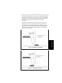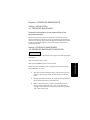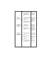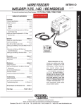
1
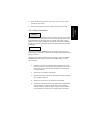
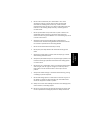
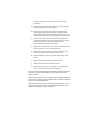
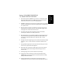
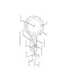
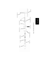
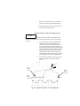
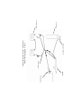
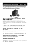
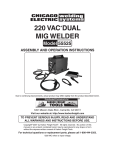
GOWELDINST SEPTEMBER 2002
Broco products are built with
your safety in mind, but it is
the responsibility of the
operator to exercise good
work practices and common
sense.
WARNING: You must read
and understand these
operating instructions
thoroughly and follow the
procedures contained herein
before attempting to use the
Broco GOWELD portable
welder. Failure to do so can
result in death, serious injury,
property damage or poor
performance.
IF YOU HAVE ANY QUESTIONS
REGARDING THE SAFE
OPERATION OF PRODUCTS,
STOP! DO NOT ATTEMPT TO
OPERATE! Contact Broco, Inc.,
Tel: 800-845-7259 / 909483-3222, fax: 909-4833233, for technical
assistance.
OPERATING
INSTRUCTIONS
MANUAL
GOWELD Portable Welder
DC Only Input: 42 VDC 300A MAX
Made in the U.S.A. by:
Broco, Inc.
8690 Red Oak St.
Rancho Cucamonga, CA 91730-4819
Tel: 909 483 3222 Fax: 909 483 3233
Toll Free: 800 845 7259
E-mail Sales @Brocoinc.com
www.brocoinc.com
WARNING:
ARC WELDING CAN BE HAZARDOUS. PROTECT YOURSELF
AND OTHERS FROM POSSIBLE SERIOUS INJURY OR
DEATH. KEEP CHILDREN AWAY. PACEMAKER WEARERS
MUST CONSULT THEIR DOCTORS BEFORE OPERATING.
WEAR PROPER FACE AND EYE PROTECTION, APPROPRIATE
PROTECTIVE (FLAME OR SPARK RESISTANT) CLOTHING,
FOOTWEAR AND GLOVES. DO NOT BREATHE WELDING
FUMES AND GASES.
?
?
?
?
?
?
ELECTRIC & MAGNETIC FIELDS MAY BE
DANGEROUS.
ELECTRIC SHOCK CAN KILL.
ARC RAYS CAN BURN EYES & EXPOSED SKIN.
FUMES & GASES CAN BE DANGEROUS.
WELDING SPARKS CAN CAUSE FIRE & EXPLOSION.
GAS CYLINDERS CAN EXPLODE IF DAMAGED.
WARNING:
Welding equipment is potentially dangerous to the
operator and persons in the area and must be used in
strict accordance with the instructions provided. Read the
instruction manual before using GOWELD. Welding should
be performed by trained individuals only and according to
industry accepted safety practices.
© 2002 by BROCO, INC. all rights reserved. This manual
may not be reproduced in whole or in part without the
express written permission of Broco, Inc.
Chapter 1
SAFETY PRECAUTIONS AND
GENERAL INFORMATION
1-1. WELDING PROCESS
1-2. WARNINGS
1-3. SAFETY PRECAUTIONS
PREPARATION
Section I. INTRODUCTION
SAFETY
INFORMATION
TABLE OF CONTENTS
Section II. EQUIPMENT DESCRIPTION
1-4. GOWELD WELDER FEATURES
PREPARATION
Section I. SETUP PROCEDURES
Section II. GOWELD SETUP
TROUBLESHOOTING
2-3. LOADING THE WIRE
2-3-1. Wire selection.
2-3-2. Contact tip.
2-3-3. Loading electrode / wire drive
2-3-4. Tension roller pressure setting.
2-4. CABLE CONNECTIONS
2-4-1. Harness to power source.
2-4-1-1. Batteries.
2-4-2. GOWELD to harness.
2-4-2-1. Choosing polarity.
2-4-2-2. Power & ground leads.
2-5. GAS CONNECTION
MAINTENANCE
2-1. PREPARING THE WORK AREA
2-2. PRE-ASSEMBLY INSPECTION
OPERATION
Chapter 2
2-5-1. Regulator adjustment.
2-5-2. Gas hose connection.
Chapter 3 OPERATING INSTRUCTIONS
Section I. INTRODUCTION
3-1. TORCH OPERATION
Section lI. OPERATING PROCEDURES
3-2. WELDING CAPABILITY
3-3. CONTROLS & SETTINGS
3-3-1. Wire speed control.
3-3-2. Voltage control.
3-3-3. LED indicators.
3-4. SEQUENCE OF OPERATION
3-5. WELDING TECHNIQUES
3-6. AUTOMATIC PROTECTION SHUTDOWN
3-7. SHUTDOWN PROCEDURES
Chapter 4 SCHEDULED MAINTENANCE
Section I. INTRODUCTION
4-1. PREVENTIVE MAINTENANCE
Section II. SCHEDULED MAINTENANCE
4-2. PREVENTIVE MAINTENANCE
PROCEDURES
Chapter 5 TROUBLESHOOTING
5-1. USING THE TROUBLESHOOTING
GUIDE.
5-2. TROUBLESHOOTING GUIDE.
Chapter 6 CORRECTIVE MAINTENANCE
GENERAL INFORMATION AND SAFETY
PRECAUTIONS
Section I. INTRODUCTION
1-1. WELDING PROCESS
GOWELD is the lightest most portable, full-function, smart
semi-automatic wire feed welder. GOWELD goes where you
go, in the field, in the shop, in the garage. With GOWELD the
operator can weld with solid wire electrode and shielding gas
(MIG) or self-shielded flux core wire electrode (FCAW). Wire
welding is the most economical welding method, due to the
high deposition rate, high efficiency, and low equipment cost.
GOWELD uses DC power from 2 (or 3) 12V rechargeable
batteries (automobile or deep cycle type) to weld steel or
aluminum. GOWELD can also be used as a spool gun for
conventional CV welding power sources utilizing an accessory
voltage regulator.
GOWELD accommodates 4” (10cm) diameter 2 lb (0.9 kg)
spools of .023 (0.6mm) to .045 (1.1mm) diameters wire
electrode to weld material in excess of 1/2” (13mm) thick. A
trigger operated valve controls the flow of the shielding gas.
GOWELD features a die cast aluminum chassis, heavy duty
motor wit h optical encoder and programmed microprocessor
control circuit to monitor feed and weld functions. Together
the optical encoder and microprocessor yield speed control
with the least variance. LED indicators show power, polarity,
low battery warning and motor status.
SAFETY
INFORMATION
Chapter 1
1-2. WARNINGS AND SAFETY PRECAUTIONS
WARNING
This statement appears where the information must
be followed exactly to avoid serious personal injury
or loss of life.
CAUTION
This statement appears where the information must
be followed to avoid minor personal injury or damage
to property.
1-2-1. Warnings.
WARNING
To avoid serious injury or death, all personnel shall heed these warnings.
a.
All users and their supervisory personnel must read and be thoroughly
familiar with these operating instructions prior to using this equipment.
b.
Never use the equipment unless you are familiar with acceptable
industrial welding and cutting procedures and practices.
c.
Always use this equipment following generally accepted industrial
safety procedures and practices.
d.
Always apply and adhere to ANSI/ASC Z49.1-1988 Safety in Welding
and Cutting standards, NFPA 51B-1989 Cutting and Welding
Processes, and ANSI Z87.1-1989 the Practice for Occupational and
Educational Eye and Face Protection, or similar locally prevailing
standards when using this equipment.
e.
Never remove, cover, or alter the warning labels attached to this
equipment.
f.
Never point the welder at anybody.
g.
Never open the GOWELD housing, no user serviceable parts are within.
Always return GOWELD to the factory or an authorized repair facility for
major repairs.
Never modify this equipment in any manner or use it in any way not
specified in this manual.
i.
Never use any equipment that is unsafe or appears to be unsafe.
1-2-2. Safety Precautions.
WARNING
Failure to heed these safety precautions may result in death, severe bodily
injury, or severe property damage. Protect yourself and others. Fumes and
gases developed may be dangerous to your health. Ultra-violet rays and
splatter can injure eyes and exposed skin. Electric shock can kill. Welding
sparks can cause fire or explosion. Compressed gas cylinders may explode
if damaged.
NOTE
Vibrations produced by GOWELD during a normal operating cycle do not
exceed 2.5m/s 2, the minimum reportable standard for hand-held and handguided machinery.
This equipment produces airborne noise emissions in excess of 70 dB(A).
GOWELD sound level has been measured at 74 dB(A) during a normal
operating cycle.
a.
Always clear the work area of flammable materials. If this is not
possible, cover them to prevent the welding sparks from starting a
fire. Always have an approved fire extinguisher in good working
condition available.
b.
Never weld in an explosive atmosphere.
c.
Always use extreme caution when operating the welder in windy or
other adverse conditions.
d.
Always clear the work area of unnecessary bystanders.
e.
The operator and all bystanders must always wear adequate face
and eye protection, protective (flame and/or spark resistant)
clothing, footwear, and gloves when using this equipment. Wear
oil free protective garments such as leather gloves, heavy shirt,
SAFETY
INFORMATION
h.
cuffless pants, high leather steel-toed work shoes, and a cap over
your head.
f.
Always use a number 10 or 11 shade welding filter lens when
welding or observing welding to protect your eyes from arc rays.
Always wear safety glasses with side shields when in a welding
area to protect from sparks.
g.
Always wear earplugs when welding in a confined space or out of
position. Falling sparks can cause injury.
h.
Always wear approved hearing protection.
i.
Always remove all personal metal items (i.e., rings, watches, etc.)
when working with the torch as they can trap sparks and slag
causing a severe burn and damage to the item.
j.
Always keep your head away from the fume plume. Welding fumes
and gases may be hazardous to your health.
k.
Always use adequate ventilation and exhaust at the arc point to
keep fumes and gases from your breathing zone as well as the
general area. Special breathing apparatus may be required when
welding in confined spaces or when welding or cutting galvanized,
cadmium plated (or other heavy metal plated), or painted parts to
avoid inhalation of toxic fumes and gases.
l.
Never weld in locations near chlorinated hydrocarbon vapors
coming from degreasing, cleaning or spraying operations.
Phosgene, a highly toxic gas, may form.
m. Always use enough ventilation in confined spaces to prevent
shielding gases from displacing air and causing injury or death.
n.
Always read and understand the material safety data sheet
(MSDS) for the electrode being used with this equipment.
o.
Always consult a physician before welding if you have a
pacemaker or history of heart problems.
p.
Always insulate yourself from the work and the ground using dry
insulation large enough to cover the full area of physical contact
with the work and ground.
Never touch live electrical parts. The welder is “hot” when
attached to a battery or other power source. The electrode,
electrode reel, welding head, contact tip, nozzle and other
exposed metal parts are also “hot.” Never touch these parts with
bare skin or wet clothing. Always wear dry, hole-free gloves to
insulate hands.
r.
Never lay the welder on top of the work or place it where it can
accidentally contact the work or ground or other metal that
contacts the work or ground. Electric arc or overheating may result
in shock or fire hazard.
s.
Always be sure the ground cable makes a good electrical
connection with the metal being welded. The connection should
be as close as possible to the area being welded.
t.
Never coil the electrode lead around your body.
u.
Never place your body between the electrode and the ground
cable.
v.
Always use a safety belt to prevent a fall should you get a shock
when working above floor level.
w.
Always keep the welder away from compressed gas cylinders, and
batteries. Protect gas cylinders and batteries from falling sparks
or molten metal.
x.
Never heat, cut or weld tanks, drums or containers unless purged
with inert gas (such as argon or nitrogen) or other steps have
been taken to insure that flammable or toxic vapors are not
present.
y.
Always vent hollow castings or containers before heating, cutting
or welding to prevent explosion.
z.
Never allow falling sparks or molten metal to contact any part of
the welder, its cables or hose. Damage may result which could
render the equipment unsafe to operate.
aa. Always use caution when welding overhead to avoid falling sparks,
molten material, and falling objects.
bb. Never use a high pressure gas cylinder that does not comply with
current inspection and testing requirements. Always ensure the
SAFETY
INFORMATION
q.
cylinder is marked with a sticker showing a valid inspection
certification.
cc. Always keep high pressure gas cylinders in an upright position,
securely chained to a cart or fixed support.
dd. Never drop a high pressure gas cylinder. Never leave a high
pressure gas cylinder in direct sunlight for prolonged periods.
Never expose a high pressure gas cylinder to fire or extreme heat.
High pressure gas cylinders can be dangerous. Use with caution.
ee. Always ensure the correct over pressure safety relief device is
installed in the high pressure cylinder valve. Never use a safety
relief device whose burst pressure is higher than that
recommended by the cylinder manufacturer.
ff.
Always keep valve protection caps in place and hand tight except
when the cylinder is in use or connected for use.
gg. Always keep your head and face away from the cylinder valve
outlet and regulator when opening the cylinder valve.
hh. Always use DC power. Never connect AC electric power to this
welder.
ii.
Always know the composition of the target material.
jj.
Always know what is behind the target material.
kk. Always ensure that all parts of the welder are in good working
order prior to use to avoid potential malfunction.
See: American National Standard Z49.1-88 Safety in Welding and Cutting
published by the American Welding Society, 550 N.W. LeJeune Road;
Miami, FL 33126.
“Recommended Safe Practices for the Preparation for Welding and Cutting
of Containers and Piping That Have Held Hazardous Substances”, AWS F4.1
from the American Welding Society.
“Precautions for Safe Handling of Compressed Gases in Cylinders,” CGA
publication P-1, available from the Compressed Gas Association, 1235
Jefferson Davis Highway, Arlington, VA 22202.
OSHA Safety and Health Standards 29 CFR 1910 available from the U.S.
Department of Labor; Washington, D.C. 20210.
1.
Dual mode operation- GOWELD can be used as a stand-alone welder
with battery power source or as a MIG spool gun for a conventional
welder when used with an accessory voltage regulator.
2.
GOWELD is designed for 42 volts DC max welding power input, allowing
the use of three batteries in series for longer duration or welding steel
to 1” (25cm) thick..
3.
Die cast aluminum chassis- all hardware is mounted to this internal
chassis (frame). It supports the motor, drive assembly, trigger, micro
switch, gas valve, circuit board and wire spool.
4.
The plastic housing shrouds the working portions of the welder,
protecting from exposure and adding visual style.
5.
Wire speed control is at the welder’s fingertips. Large knob has easy to
read numbers. Each graduation represents 100 inches (250cm) per
minute (ipm). Operating range of 50 - 1,000 ipm (125 – 2,500
cm/minute).
6.
Voltage control dial integral to gun is for use with the accessory voltage
control unit, “VCU,” to allow reduction of voltage for welding on thin
metal.
7.
Spring loaded, hinged top cover for easy electrode loading. Over sized
knob is easy to grasp while wearing gloves.
8.
Heavy duty drive mechanism includes high torque 12 volt industrial
motor containing oversized windings and ball bearings to ensure
maximum life.
9.
Knurled gearing is steel. Tension wheel has ball bearings.
10. Locking cam tension release lever means easy electrode loading.
GOWELD does not require application of constant pressure to offset
spring loaded tension wheel.
11. Optical encoder fitted to the back of the motor gives true speed
readings. More accurate and responsive than back EMF type systems.
SAFETY
INFORMATION
Section 2. EQUIPMENT DESCRIPTION
1-4. GOWELD WELDER FEATURES
12. Programmed microprocessor controls and monitors feed and weld
functions. Together the optical encoder and microprocessor yield
speed control with the least variance. More consistent speed means
more consistent welds. Battery levels are also monitored.
13. Diagnostic capabilities through the control circuit interface cable. No
disassembly is required for testing the board, processor or motor.
14. Handle mounted micro switch is more durable than board mounted
switches. Micro switch and gas valve are both operated directly off the
trigger.
15. LED indicators for power on, polarity, low battery and motor overheat
condition.
Wire Speed Control Knob
Fig. 1.1 GOWELD Side View
Red Low Battery LED
Yellow Volt - LED
Yellow Volt + LED
Green Power LED
Contact Tip
Nozzle
Trigger
Voltage Control Knob
Top Cover
Top Cover Knob
SAFETY
INFORMATION
Spool Hub
Spool Locking Screw
Chassis
Wire Electrode Guide
Tension Release Lever
Rear Guide Tube
Drive Rollers
Tension Roller Adjusting Knob
Front Guide Tube
Fig. 1.2 GOWELD Top View
Wire Electrode
Front Block Assembly
Chapter 2
PREPARATION
Section I. SETUP PROCEDURES
2-1. PREPARING THE WORK AREA
WARNING
Never operate the welder in explosive or flammable environments.
Always use extreme caution when operating the welder in windy or other
adverse conditions.
Some plastics, paints, and plated parts give off toxic fumes. Organic
materials may be combustible. Exotic metals may ignite. Glass and thin
porcelain may shatter. Rock and minerals may spall.
a.
Clear the work area of bystanders/non-essential personnel.
b.
Clear the work area of flammable materials. If this is not possible,
cover them to prevent the welding sparks from starting a fire. Always
have an approved fire extinguisher in good working condition available.
c.
The operator and all bystanders must always wear adequate face and
eye protection, protective (flame and/or spark resistant) clothing,
footwear, and gloves when using this equipment. Wear oil free
protective garments such as leather gloves, heavy shirt, cuff-less
pants, high leather steel-toed work shoes, and a cap over your head.
d.
Place the batteries and gas cylinder in a location away from the
immediate work area.
e.
When the target material is a container or pipe, know the material
previously contained therein. Always thoroughly purge pipelines and
containers with an inert gas (such as nitrogen or argon) prior to
welding.
f.
Ensure that falling material (molten metal, sparks, pieces of target
material) will not cause injury to operator or bystanders or cause
damage to property.
PREPARATION
Never operate the welder with other personnel or bystanders in front of the
welder or in the immediate work area.
2-2. PRE-SETUP INSPECTION.
WARNING
Never use any equipment which is unsafe or appears to be unsafe.
a.
Always inspect the power cables, gas hose, control circuit cable and
electrical connectors for damage or wear prior to and immediately
following each use of the welder.
b.
Always inspect the welder for damage or wear prior to and immediately
following each use.
c.
Check the battery for leaks. Never use a leaking battery as gases may
be toxic and/or combustible. Seepage may be caustic, harming skin
and eyes.
Section II. GOWELD SETUP
2-3. LOADING THE WIRE
WARNING
Never load electrode wire or remove or replace the contact tip, gas diffuser,
or other parts while the power cables are connected to the batteries or to
any other power source.
Always remove the battery cable harness clamps from the batteries before
loading electrode wire or removing or replacing the contact tip, gas diffuser
or other parts.
NOTE
Tools required are pliers, 1/2” (13mm) open end wrench, 9/16” (14mm)
open end wrench and wire cutters (dikes).
2-3-1. Wire selection.
GOWELD can be used with solid steel or aluminum wire or fluxcored steel wire depending upon the job requirements and
availability of shielding gas. Solid steel wire (ER70S, AWS
SFA5.18) requires the use of “Steel Mix” shielding gas (argon/
CO2 mix); aluminum wire (AWS SFA5.10) requires argon shielding
gas; and flux-cored steel wire (E71T, AWS SFA5.20) is gasless.
GOWELD accepts wire sizes from .023” (0.6mm) - .045” (1.1mm)
diameter. Choose a size appropriate for the material being
welded. As a general rule, GOWELD works best over a wide range
of material thicknesses using .030” (0.8mm) or .035” (0.9mm)
wire.
2-3-2. Contact tip.
Remove the contact tip and the gas diffuser prior to loading the
electrode wire.
a.
Remove the nozzle by gripping it firmly in a gloved hand and
pulling it straight off the GOWELD.
b.
Remove the nozzle insulator by gripping it firmly with a gloved
hand (or pliers if on too tight) and turning it counterclockwise
until the threads are clear of the gas diffuser.
c.
Use a 1/2” (13mm) wrench to hold the gas diffuser in place,
grip the contact tip with the pliers and turn counterclockwise
until disengaged from the gas diffuser. Remove the contact
tip.
d.
Use a 9/16” (14mm) wrench to hold the front block
extension, while using the 1/2” (13mm) wrench to turn the
gas diffuser counterclockwise until the threads are
disengaged from the front block extension. Remove the gas
diffuser.
2-3-3. Loading electrode / wire drive
a.
Ensure the gas diffuser and contact tip have been removed
as per the previous step.
b.
Open the GOWELD top cover by turning the top knob
counterclockwise until the threads are disengaged from the
spindle. Lift lid carefully until it is fully extended. Do not allow
the retention spring to slam the lid open. The retention spring
will support the lid, keeping it from falling.
PREPARATION
Welding current is transmitted to the electrode through the
contact tip. It is important that the orifice in the contact tip is sized
to correspond to the diameter of the wire electrode (i.e. use .030”
[0.8mm] contact tip with .030” [0.8mm] wire).
c.
Turn the spool locking screw counterclockwise to reduce the
diameter of the spool hub shaft. This will allow the electrode
spool to slide over the shaft and rest on the spool hub.
d.
Lift up on the tension release lever to open the gap between
the drive roller and tension roller.
e.
While tightly holding the electrode to prevent it from
unspooling, cut off the bent end and straighten the first 6
inches (15cm). Cut off the first inch (2.5cm).
f.
Insert the wire end into the front guide tube, pushing it
through the gap in the drive rollers and into the rear guide
tube until the end of the wire protrudes approximately 2”
(5cm) from the front block extension.
g.
Lower the tension release lever to engage the electrode wire
with the drive rollers.
h.
Place the roll of electrode wire onto the spool hub with the
tailing end coming off the right side to point towards the front
of the welder. Make sure the index pin on the spool hub
engages a slot on the bottom of the spool. Tear away paper
label on spool to expose slot if necessary.
i.
Finger tighten the spool locking screw by turning it clockwise
until increased resistance is felt.
j.
Slide the gas diffuser over the wire and thread onto the front
block extension. Tighten using the 1/2” (13mm) and 9/16”
(14mm) wrenches.
k.
Slide the correct size contact tip over the wire and thread
onto the gas diffuser. Use the pliers and 1/2” (13mm)
wrench to tighten.
l.
Replace the insulator, finger tighten.
m. Replace the gas nozzle by pressing it on to the front of the
welder. Adjust nozzle setback to allow for appropriate wire
stick out for electrode type and size.
Nozzle
Contact Tip
Insulator
Drive Rollers
Rear Guide Tube
Spool Locking Screw
Tension Release Lever
Front Guide Tube
Fig. 2.1 Wire Electrode Path
Front Block Assembly
Gas Diffuser
PREPARATION
Spool Hub
2-3-4. Tension roller pressure setting.
NOTE
The tension roller pressure is set at the factory to accommodate .035”
(0.9mm) flux cored wire.
a.
Set the tension roller pressure as light as possible to maintain a
continuous feed while minimizing wire distortion.
b.
The knurled adjusting knob rotates counterclockwise to reduce
pressure and clockwise to increase pressure.
c.
With the wire loaded and the power cables attached point the
welder at a non-conductive hard object (a concrete floor or wall for
example) with the contact tip approximately two inches from the
surface.
d.
Depress the trigger causing wire to beginning spooling out at low
speed, approximately 100 inches (250cm) per minute. As the wire
hits the surface it should be turned aside, coiling the wire.
e.
Slowly turn the adjusting knob counterclockwise until the wire
begins to slip in the rollers. Remove pressure from the trigger to
shut down the drive system.
f.
Turn the adjusting knob ½ turn clockwise.
g.
Test to ensure there is no longer any slippage by again depressing
the trigger and observing the wire and spool.
2-4. CABLE CONNECTIONS
2-4-1. Harness to power source.
WARNING
Never allow the GOWELD to unintentionally contact any part of the
workpiece or other surface that may be grounded into the welder circuit as
electric shock may occur. Once the GOWELD has been attached to the
power source the electrode is always “hot.” The trigger controls the drive
motor and gas flow only, GOWELD does not have an internal contactor.
NOTE
2-4-1-1. Batteries.
NOTE
GOWELD’s control circuit input must be kept to only 24 volts DC. Welding
power can be from a combination of two (or three) 12v batteries.
Using 2 batteries. (24 volt welding power)
a.
Join the batteries in series using the jumper
cable provided. Attach one end of the cable to
the positive terminal of the first battery and the
other end of the cable to the negative terminal
of the second battery.
b.
Attach the black (negative-) clamp to the open
negative (-) terminal on the first battery.
Red
Battery
Clamp
Black
Battery
Clamp
Red
Micro
Clamp
12 Volt
12 Volt
Fig. 2.3 GOWELD Harness To Two Batteries
PREPARATION
If the clamps are not on the proper terminal, the gun will not operate. When
the cables are correctly attached to the batteries and the green LED power
indicator will light and the motor will operate when the trigger is depressed.
If the clamps are attached to the wrong terminals on the batteries the LED
indicator will not light and the motor will not operate.
c.
Attach the red (positive+) clamp to the open
positive (+) terminal on the second battery.
d.
Attach the red micro clamp to the positive (+)
terminal of the second battery.
Using 3 batteries. (36 volt welding power)
NOTE
While welding power can be 36 volts, input power to the welder control
circuit must be 24 volts. The red micro clamp is for control circuit power
input only.
a. Join the batteries in series using the jumper
cable provided and a second cable (one
element of an automotive jumper cable set
may be used). Attach one end of the cable to
the positive terminal of the first battery and the
other end of the cable to the negative terminal
of the second battery. Attach one end of the
second cable to the positive terminal of the
second battery and the other end of that cable
to the negative terminal of the third battery.
b.
Attach the black (negative-) harness clamp to
the open negative (-) terminal on the first
battery.
c.
A
t
t
a
c
h
Red
Battery
Clamp
Black
Battery
Clamp
t
h
e
Red
Micro
Clamp
r
e
d
12 Volt
12 Volt
12 Volt
Fig. 2.4 GOWELD Harness To Three Batteries
c.
Attach the red micro clamp to the positive (+)
terminal of the second battery.
d.
Attach the red (positive+) harness clamp to the
open positive (+) terminal on the third battery.
2-4-2. GOWELD to harness.
2-4-2-1. Choosing polarity.
? Solid steel electrode- weld with Reverse polarity, electrode
(welder) positive, ground cable negative.
? Stainless steel electrode- weld with Reverse polarity, electrode
(welder) positive, ground cable negative.
? Flux-core self shielding steel electrode- weld with Straight
polarity, electrode (welder) negative, ground cable positive.
? Aluminum- weld with Reverse polarity, electrode (welder)
positive, ground cable negative.
? Flux-core hardfacing wire- weld with Reverse polarity,
electrode (welder) positive, ground cable negative.
2-4-2-2. Power & ground leads.
a.
Straight polarity- mate the welder power cable connector
with the connector attached to the black (negative) battery
clamp. Mate the ground cable connector with the connector
attached to the red (positive) battery clamp.
b.
Reverse polarity- mate the welder power cable connector
with the connector attached to the red (positive) battery
clamp. Mate the ground cable connector with the connector
attached to the black (negative) battery clamp.
PREPARATION
Connect the GOWELD to the power harness by plugging the 5-pin
control cable connectors together and mating the appropriate
welder power and ground cable connectors with the harness cable
connectors.
Gas Supply
12 Volt Batteries
12 Volt
Regulator Or Flowmeter
12 Volt
Power Harness
Fig. 2.5 GOWELD System Setup
(Two battery reverse polarity illustrated.)
GOWELD
Ground Clamp
2-4-3. Ground cable to work.
WARNING
Never position the ground cable where the operator’s body can come
between the work and the ground. Always position the ground cable away
from the welder.
2-5. GAS CONNECTIONS
2-5-1. Gas hose connection.
GOWELD has a “B” size inert gas fitting on the gas hose. Attach
the GOWELD hose to the regulator or flow meter outlet fitting by
threading the nut into the fitting. If the regulator fitting has a male
thread, a FEM “B”-FEM “B” adaptor will be required.
2-5-2. Regulator adjustment.
WARNING
Never stand directly in front of or directly behind the gas regulator while
opening the gas cylinder valve to reduce the risk of injury in the unlikely
event of regulator failure.
a.
Shielding gas flow rate should be set to approximately 20cfh.
b.
Open the gas cylinder valve slowly.
c.
Slightly depress the GOWELD trigger to begin the flow of gas.
Do not press so far that the wire feed motor is activated.
d.
With the gas flowing, adjust the regulator delivery pressure to
20 psig (1.5 bar) or the flow meter indicator to 20 cfh.
e.
Release the trigger to stop the flow of gas.
PREPARATION
Attach the ground cable clamp to the item being welded. Be sure that the
clamp is secure and that it is positioned away from the operator.
Chapter 3
OPERATING INSTRUCTIONS
Section I. INTRODUCTION
3-1. GOWELD OPERATION
WARNING
Never operate the welder in explosive or flammable environments.
Never operate the welder with other personnel or bystanders in front of the
welder or in the immediate work area.
Always use extreme caution when operating the welder in windy or other
adverse conditions. Nearby organic materials may be combustible.
Never breathe welding fumes. Some plastics, paints, and plated parts give
off toxic fumes.
The welder operates on the following principle. GOWELD conducts electrical
energy from a set of batteries through an alloy wire welding electrode to a
grounded workpiece, causing the tip of that electrode to go molten in the
arc and transfer to the work where it fuses with the base material creating a
buildup of alloy filler material (the “weld”). A pair of control knobs allow the
operator to set the electrode wire feed speed (range 0” – 1000” [2,500cm]
per minute) and (when the optional remote voltage control unit is installed)
adjust the welding voltage. The trigger opens the gas valve so that gas will
flow out the tip of the unit to surround the welding wire and shield the weld
puddle. The trigger also operates the micro switch which enables the wire
feed motor.
3-2. WELDING CAPABILITY
Welding duration is dependent upon the batteries being used as the power
source. Larger capacity deep cycle 12v batteries will provide the most
welding “arc time” between charges. On average 10-20 minutes of welding
arc time can be performed with GOWELD on one set of batteries.
GOWELD operates at 50% duty cycle, which means GOWELD can be used
for 5 minutes of arc-time in a 10 minute period to stay within the operating
temperature parameters.
GOWELD will accommodate welding wire of .023” (0.6mm) -.045” (0.9mm)
diameter. GOWELD can be used to weld material ranging from 1/8” (3mm)
thickness to 1” (25mm).
GOWELD can be used to weld with:
? Steel- Solid wire
? Steel- Self shielding wire
? Aluminum- Solid wire
? Stainless- Solid wire
? Hardfacing- Cored wire
3-3. CONTROLS & SETTINGS
3-3-1. Wire speed control.
The wire speed control is indexed to the value on the control knob
X100. Example: The “4” mark on the knob correlates to
approximately 400 inches per minute (ipm).
Turning the knob clockwise increases the wire speed while turning
the knob counter-clockwise decreases wire speed.
Optimum speed will result in a stable arc, smooth transfer of weld
material to the work, good bead profile, good penetration and
constant stick-out.
3-3-2 Voltage Control.
The accessory voltage control unit is installed in the welding
circuit between the GOWELD and the battery power source. The
voltage control unit reduces the welding voltage with minimum
power loss to facilitate welding thin gauge metals without burn
through.
See “Voltage Control Installation & Operation Instructions” which
are included with the accessory voltage control unit.
3-3-3 LED INDICATORS
There are 4 LED indicators on the GOWELD unit and their
operation is as follows:
OPERATION
There is a direct relationship between welding wire speed and the
welding current (in amps). As the wire speed changes up or down
the welding current changes in the same direction (up or down).
?
Green “POWER” LED will illuminate when control circuit
power is supplied to the GOWELD through the control
cable. The voltage supplied must be 24vDC for proper
operation. The green LED will flash slowly to indicate
motor overheat condition. When the motor has cooled
sufficiently the green LED will return to a steady light.
The green LED will flash rapidly in the case of wire jam to
indicate the motor is not turning. (See 3-6-1 & 3-6-2.)
?
Yellow “Volt+” and “Volt-“ LEDs are welding polarity
indicators. When the welding power to the GOWELD is
connected to either the + or – terminal of the supply
battery, one of these LEDs will come on to indicate the
polarity of that connection. (See 2-4-2-1.)
?
Red “Low Battery” LED is normally off. As the battery
voltage drops during use, this LED will begin to flash. The
rate of flashing will increase as the voltage drops closer
to the preset low battery limit (14 volts for two batteries
and 21 volts for 3 batteries) . The flashing will stop with
the LED on continuously when the voltage drops below
the low battery limit. If the trigger was on when the low
battery limit is reached, the motor will stop automatically
in order to prevent damage to the batteries from
discharging them too far. When this condition is active,
the LED will stay on until the trigger is released at which
time the LED will begin to flash again as the batteries
recover. The low battery limit is established at 19 volts
for a 2 battery system and 29 volts for a 3 battery
system. (See 3-6-3.)
3-4 SEQUENCE OF OPERATION
WARNING
Never use the equipment unless you are familiar with acceptable industrial
welding and cutting procedures and practices.
Always use this equipment following generally accepted industrial safety
procedures and practices.
The operator and all bystanders must always wear adequate face and eye
protection, protective (flame and/or spark resistant) clothing, footwear, and
gloves when using this equipment. Wear oil free protective garments such
as leather gloves, heavy shirt, cuffless pants, high leather steel toed work
shoes, and a cap over your head.
Always use a number 10 or 11 shade welding filter lens when welding or
observing welding to protect your eyes from arc rays. Always wear safety
glasses with side shields when in a welding area to protect from sparks.
Always keep your head away from the fume plume. Welding fumes and
gases may be hazardous to your health.
Always use adequate ventilation and exhaust at the arc point to keep fumes
and gases from your breathing zone as well as the general area. Special
breathing apparatus may be required when welding in confined spaces or
when welding or cutting galvanized, cadmium plated (or other heavy metal
plated), or painted parts to avoid inhalation of toxic fumes and gases.
Always use enough ventilation in confined spaces to prevent shielding
gases from displacing air and causing injury or death.
Never lay the welder on top of the work or place it where it can accidentally
contact the work or ground or other metal that contacts the work or ground.
Electric arc or overheating may result in shock or fire hazard.
1.
Check/prepare the work area.
2.
If a shielding gas is to be used, attach the regulator to the gas
cylinder then connect the gas line to the regulator. Set the
regulator to the appropriate gas delivery pressure.
3.
Attach the jumper cable to the batteries.
4.
Attach the harness to the batteries.
5.
Attach the ground clamp to the work.
6.
Load the wire electrode.
7.
Check to see that the selected contact tip is the appropriate size
for the electrode being used. Install the diffuser, contact tip and
nozzle.
OPERATION
Always insulate yourself from the work and the ground using dry insulation
large enough to cover the full area of physical contact with the work and
ground.
8.
Connect the GOWELD control circuit cable.
9.
Set the wire feed speed as per section 3-3-2.
10. Connect the GOWELD welding power cable and ground cable to
the harness making sure the polarity is appropriate for the
electrode being used.
11. Bring the welder into position near the work piece.
12. Ensure eye protection is in place. Make sure auto darkening
lenses are turned “on”.
13. Squeeze the trigger to commence welding.
14. To stop welding release the trigger and pull GOWELD away from
the work.
3-5 WELDING TECHNIQUES
? Position the tip of the electrode over the place on the work where the
weld is to start.
? Hold GOWELD so the angle of the welder relative to the length of the
weld is approximately 10°-25° from vertical. The angle of the welder
relative to the plate is approximately 45° for filet welding or 5°from
vertical for a beveled butt joint.
? Use the backhand method (where the wire feeds opposite the
direction of travel, filler metal is deposited into the previous welddrag) for flat, horizontal, overhead and vertical down welding
positions.
? Use the forehand method (where the wire feeds in the direction of
travel, filler metal is deposited directly on the workpiece- push) for the
vertical up welding position.
? Travel speed should be between 10” (25cm) per minute and 13”
(33cm) per minute. Vary the travel speed while welding a test coupon
to determine the rate that yields the best penetration for that
application and the operator’s technique.
? Wire stickout (the distance from the contact tip to the work) should be
maintained at between 3/8” (9mm) and ¾” (19cm) depending upon
the electrode type and size, wire feed speed and material thickness.
Generally a longer stickout and high wire feed speed are preferable
for welding thin materials, while less stickout will increase
penetration.
? Torch manipulation (“weaving”) allows the operator to obtain the
desired fill with a minimum number of passes. As a general rule a
small circular motion is recommended for fillet welds. A back-andforth weave with a slight pause at the sides is typically used for butt
weld root passes and fill passes. Adjust the weave for the desired
width of the resultant weld.
Direction of Travel
Torch angle 10°- 25°
From Vertical
Direction of Travel
Torch angle 10°- 25°
From Vertical
Fig. 3.2 Forehand Technique
OPERATION
Fig. 3.1 Backhand Technique
Torch angle 45°
From Vertical
Fig. 3.3 Transverse Angle Filet Weld
Torch angle 5° From
Vertical
Fig. 3.4 Transverse Angle Butt Weld
Position variations:
o
Vertical up- Butt weld root passes are made with a slight “U”
pattern. Fill passes are made using a side to side weave with
a very slight backstep at the sides. Fillet welds are made
using an inverted angle, up to the center then down to the
opposite side, pause, up to the center and so on.
o
Vertical down- An inverted “u” is used for butt weld root and
fill passes and filet welds. Keep the arc on the leading edge
of the puddle for best penetration.
o
Overhead- Butt weld root, fill and cover passes and filet
welds are all made using a back and forth weave with a
slight pause at the sides.
Direction
of Travel
Fig. 3.5 Vertical Down & Vertical Up Filet Welds
OPERATION
Direction
of Travel
3-6 AUTOMATIC PROTECTION SHUTDOWN
NOTE
GOWELD has been designed to automatically shut down to prevent damage
to GOWELD’s motor, circuits or the batteries. In the event GOWELD appears
to cease operation while welding look first to one of the following
conditions.
3-6-1 OVERHEAT PROTECTION
GOWELD’s motor is equipped with an external thermister which
continuously sends temperature data to the microprocessor.
When the motor temperature reaches 100°C the overheat
protection program will shut the motor off.
Overheat protection is indicated by the slowly flashing green
“power” LED.
Allow GOWELD to cool a few minutes then continue welding.
3-6-2 WIRE JAM CONDITION
In the unlikely event of a wire jam preventing the welder’s motor
from turning while the trigger is being pulled, the microprocessor
will cease sending current to the motor to prevent damage to the
motor or other components.
Wire jam condition is indicated by the rapidly flashing green
“power” LED.
Disconnect the welder from the batteries, open the GOWELD top
cover, remove the jammed wire, check the wire path and reload
the wire.
3-6-3 LOW BATTERY CONDITION
Rechargeable batteries can often be damaged by depleting them
too far before charging, shortening battery life. GOWELD’s
microprocessor monitors battery voltage level and causes a
shutdown before the voltage drops to potentially damaging levels.
When the combined voltage of the two batteries falls below 19
volts while welding (29 volts for three batteries), the red “low
battery” LED will begin to flash. The rate of flashing will increase
as the voltage drops closer to the preset low battery limit.
When the combined voltage of the two batteries falls to 14 volts
(21 volts for three batteries), GOWELD’s battery protection
program will shut the motor off. The red “low battery” LED will
remain constantly “on” while the trigger is depressed.
Recharge the batteries or exchange for a fresh set to resume
welding.
3-7 SHUTDOWN PROCEDURES
Remove the cable harness from the batteries.
2.
Disconnect the GOWELD power cable and ground cable from the
harness.
3.
Disconnect the control circuit cable from the harness. Grasp the
connector firmly in both hands. Depress the locking tab while
pulling straight apart. Do not pull on the wires.
4.
Close the gas cylinder valve. Depress the trigger to relieve the
pressure from the gas hose. Disconnect the gas hose from the
regulator and remove the regulator from the cylinder. (Replace the
cylinder valve protector cap.)
5.
Cut off the melted end of the electrode wire.
6.
Open the GOWELD top cover by turning the top knob
counterclockwise until the threads are disengaged from the
spindle. Lift lid carefully until it is fully extended. Do not allow the
retention spring to slam the lid open. The retention spring will
support the lid, keeping it from falling.
7.
Twist the spool locking screw counterclockwise to reduce the
diameter of the spool hub shaft.
8.
Remove the electrode spool from the spool hub while keeping
tension on the wire to prevent “bird nesting.”
OPERATION
1.
9.
While keeping pressure on the wire with a finger, raise the on the
tension release lever to open the gap between the drive roller and
tension roller.
10. Pull back on the wire to remove it from the GOWELD front end.
Secure the free end of the electrode through a hole in the spool
for storage.
11. Lower the tension release lever.
12. Wipe the inside of the GOWELD with a clean dry cloth to remove
any dust or debris. Close and secure the lid.
13. Remove the nozzle and clean the nozzle, tip and torch front end.
14. Remove the jumper cable from the batteries.
15. Wipe the GOWELD, cables and accessories with a clean cloth and
replace in the carrying case.
16. Charge the batteries according to the instructions for the batteries
in use and the appropriate battery charger.
Chapter 4 SCHEDULED MAINTENANCE
Section I. INTRODUCTION
4-1. PREVENTIVE MAINTENANCE
Preventive maintenance is the responsibility of the
equipment operator.
Preventive maintenance should be conducted in accordance with this
manual and consist of inspecting, servicing, and cleaning. Inspections will
also reveal the need for repairs. Periodic inspections will ensure the welder
is safe and serviceable. Regulator repairs should only be performed by
qualified technicians.
Section II. SCHEDULED MAINTENANCE
4-2. PREVENTIVE MAINTENANCE PROCEDURES
WARNING
Prior to conducting any maintenance, ensure proper shut down procedures
are followed.
Never touch electrically hot parts.
Always disconnect the welder power and ground cables from the battery
when GOWELD is not in use.
1.
After each use wipe the welder, cables, cable harness, gas hose
regulator, battery jumper cable, and batteries with a clean dry
cloth.
2.
Remove the nozzle and contact tip, inspect for damage and wear.
Clean, replace if necessary, and reassemble.
3.
Before and after each use, conduct a close inspection of the
cables and hoses. Check for cuts, burns, or any other sign of
damage or wear. After every use, wipe down all cables and hoses
with a clean, oil-free cloth.
MAINTENANCE
Never operate GOWELD with the covers removed.
4.
Wipe the interior of the GOWELD with a clean dry cloth.
5.
Every six months, or following a period of heavy use:
a. Remove the plastic lid and handle halves and inspect the
circuit board, motor and drive assembly. Gently blow
accumulated dirt from all components using compressed air.
b.
Lubricate the gear teeth with a small amount of high
temperature resistant grease. Use caution to avoid getting
grease on the drive roller surface.
c.
Do not use any solvents to clean the tension roller because it
may wash the lubricant out of the bearings.
d.
Do not lubricate the spool hub or friction pad.
Chapter 5 TROUBLESHOOTING
5-1. USING THE TROUBLESHOOTING GUIDE.
This guide is intended to assist in determining the probable causes of torch
malfunctions and their associated repairs. For each potential problem
identified, a probable cause and recommended repair procedure is listed.
5-2. TROUBLESHOOTING GUIDE.
PROBABLE
CAUSE
RECOMMENDED
REPAIR
PROCEDURES
1.
“POWER” LED
DOES NOT LIGHT.
NOTHING
HAPPENS WHEN
THE TRIGGER IS
DEPRESSED.
a.
The cable harness clamps
are not connected to the
correct battery terminals.
Double check the
harness clamp
connections with
the batteries, the
battery jumper
cable connection,
and the control
cable circuit plug
connection.
“POWER” LED
LIGHTS BUT
MOTOR DOES
NOT RUN WHEN
THE TRIGGER IS
PULLED.
a.
Batteries may not have
sufficient charge.
(Accompanied by blinking
red “Low Power” LED.)
Check the
batteries’ condition
of charge. Replace
if necessary.
2.
OR
b. The control circuit power
cable red micro clamp is
not connected to the
positive (+) battery
terminal.
OR
c. The battery jumper cable
may be damaged or
missing.
OR
d. The control circuit cable
connector is not plugged
in to the cable harness or
damaged.
OR
b. Overheat protection may
be shutting motor off.
(Accompanied by slowly
flashing green “Power”
LED.)
Allow GOWELD to
cool a few minutes
until green LED
stops blinking.
TROUBLESHOOTING
TYPE OF
PROBLEM /
MALFUNCTION
OR
c. Wire jam protection may
be shutting motor off
(accompanied by rapidly
flashing green “Power”
LED.)
3.
4.
5.
POLARITY
INDICATOR LED
DOES NOT COME
ON.
a.
THERE IS NO ARC
BETWEEN THE
ELECTRODE AND
THE WORK.
a.
THE MOTOR
RUNS BUT THE
WIRE DOES NOT
FEED SMOOTHLY.
a.
Clear the wire jam,
inspect the wire
path and reload
the electrode.
The welder power cable is
not correctly connected to
the cable harness or
damaged.
Double check the
welder power cable
connection to the
harness. Make
sure all battery
connections are
correct.
The ground is not
correctly attached to the
work or damaged.
Double check the
ground cable
connection to the
harness. Make
sure the ground
clamp is securely
attached to the
work, with good
metal-to-metal
contact.
The drive roller tension
adjustment may be too
loose.
Check drive roller
tension adjustment
as per section 2-34 above.
OR
b. The large red clamp is not
connected to the positive
(+) battery terminal.
OR
b. The ground cable
connector is not correctly
connected to the cable
harness.
OR
b. The wire may be tangled
on the spool.
OR
c. The contact tip may be
clogged.
OR
d. The drive rollers may be
contaminated with excess
dirt, residue or grease.
Inspect the wire
spool for tangles,
replace if
necessary.
Clean or replace
the contact tip.
Clean drive rollers.
6.
THE WELDING
ARC IS
UNSTEADY,
INTERMITENT.
a.
Batteries may not have
sufficient charge.
(Accompanied by blinking
red “Low Power” LED.)
OR
b. The contact tip is dirty,
worn or the wrong size.
OR
c. The wire speed is set too
low.
OR
d. The ground connection is
not making sufficient
contact with the work.
OR
e. The metal to be welded
has not been sufficiently
cleaned of oil, paint or
rust.
Check the
batteries’ condition
of charge. Replace
if necessary.
Clean or replace
the contact tip.
Increase the wire
speed/amperage.
Make sure the
ground clamp is
securely attached
to the work, wi th
good metal-tometal contact.
Ensure the metal
to be welded is
clean, with all
paint, rust and oils
removed.
TROUBLESHOOTING
Chapter 6 CORRECTIVE MAINTENANCE
Major repairs to the GOWELD including but not limited to
circuit board testing and replacement, motor replacement
and drive assembly replacement should only be done by the
factory or its authorized repair center. Contact Broco, Inc. at
(800) 845-7259, (909) 483-3222, Fax (909) 483-3233, email [email protected] for return authorization or other repair
information.
--NOTES--