1
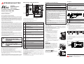
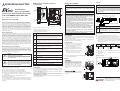
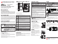
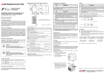
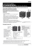
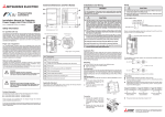
External Dimensions and Part Names
�
POWER
LINK
�
ACT
SD
RD
�
�
�
65.5 �
Programmable
Controllers
P
�
Installation Manual for ETHERNET
Adapter FX2NC-ENET-ADP
�
�
E
쐈
�
Art-no.: 160241 ENG, Version A, 22092009
�
Safety Information
19.1
7
쐅
74
For qualified staff only
This manual is only intended for use by properly trained and qualified electrical
technicians who are fully acquainted with automation technology safety standards. All work with the hardware described, including system design, installation, setup, maintenance, service and testing, may only be performed by
trained electrical technicians with approved qualifications who are fully
acquainted with the applicable automation technology safety standards and
regulations.
78
Weight: 0.1 kg (0.22 lbs)
All dimensions are in "mm".
� Distance to screw hole.
� Distance between screw holes.
� Distance to center of DIN rail.
Proper use of equipment
The programmable controllers (PLC) of the MELSEC FX1S, FX1N and FX2NC
series are only intended for the specific applications explicitly described in this
manual or the manuals listed below. Please take care to observe all the installation and operating parameters specified in the manual. All products are
designed, manufactured, tested and documentated in agreement with the
safety regulations. Any modification of the hardware or software or disregarding of the safety warnings given in this manual or printed on the product can
cause injury to persons or damage to equipment or other property. Only accessories and peripherals specifically approved by MITSUBISHI ELECTRIC may be
used. Any other use or application of the products is deemed to be improper.
Relevant safety regulations
All safety and accident prevention regulations relevant to your specific application must be observed in the system design, installation, setup, maintenance,
servicing and testing of these products.
In this manual special warnings that are important for the proper and safe use
of the products are clearly identified as follows:
P
E
No.
Description
�
Direct mounting hole:
2 holes of 4.2 mm diameter (mounting screw: M4 screw)
�
POWER LED (green):
Lit when 5 V DC is supplied from the PLC.
�
LINK LED (green):
Lit while the FX2NC-ENET-ADP is connected to the Hub and the
power is on.
쐏
ACT LED (red):
Lit while transferring data with connected Ethernet.
쐄
SD LED (red):
Lit when sending data to the connected PLC. (Refer also to the section "Ethernet Parameter Setting".)
쐂
RD LED (red):
Lit when receiving data from the connected PLC. (Refer also to the
section "Ethernet Parameter Setting".)
�
Extension cable:
Used to connect the base unit.
쐊
RJ45 modular jack:
Used to connect the Ethernet cable.
쐎
Terminal block for grounding (The three terminals are internally
connected.)
쐅
DIN rail mounting hook
쐈
DIN rail mounting groove (DIN rail: DIN46277)
Further Information
The following manuals contain further information about the modules:
쎲 Hardware Manual for the FX1S Series
쎲 Hardware Manual for the FX1N Series
쎲 FX Programming Manual
쎲 Operation Manual for Configuration Software FX Configurator-EN
쎲 Installation Guide for Communications Adapter FX1N-CNV-BD
These manuals are available free of charge through the internet
(www.mitsubishi-automation.com).
If you have any questions concerning the programming and operation of the
equipment described in this manual, please contact your relevant sales office
or department.
E
DANGER
Applicable Standard
FX2NC-ENET-ADP manufactured from April 1st, 2004 to April 30th, 2006 comply
with EN61000-6-4, EN61131-2:1994+A11:1996+A12:2000 and EN61000-6-2.
FX 2 N C -ENET-ADP manufactured from May 1st, 2006 comply with
EN61131-2:2003.
Note for compliance to the EMC regulation
It is necessary to install the FX2NC-ENET-ADP in a shielded metal control panel.
CAUTION
쎲 Do not lay signal cables close to the main circuit, high-voltage power
lines, or load lines. Otherwise effects of noise or surge induction are
likely to take place. Keep a safe distance of more than 100 mm from
the above when wiring.
Cut off all phases of the power source externally before starting the
installation or wiring work, thus avoiding electric shock or damages to
the product
45 �
FX2NC-ENET-ADP
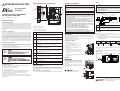
Wiring
Installation and Wiring
10 �
16.1
�
90
MITSUBISHI ELECTRIC
쎲 Fix the ETHERNET cable so that the connector is not directly stressed.
CAUTION
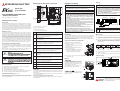
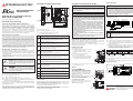
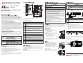
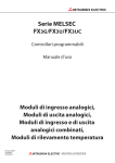
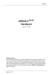
System Configuration
쎲 Use the product in the environment within the general specifications
described in the Hardware Manual. Never use the product in areas
with dust, oily smoke, conductive dusts, corrosive or flammable gas,
vibrations or impacts, or expose it to high temperature, condensation, or wind and rain.
If the product is used in such a place described above, electrical shock,
fire, malfunction, damage, or deterioration may be caused.
FX2NC-ENET-ADP
FX1S/FX1N
PC
FX2NC-ENET-ADP
FX1S/FX1N
....
쎲 When drilling screw holes or wiring, cutting chips or wire chips should
not enter ventilation slits. Such an accident may cause fire, failure or
malfunction.
�
Hub
�
쎲 Be sure to remove the dust proof sheet from the PLC's ventilation port
when the installation work is completed. Failure to do so could can
cause fires, equipment failure, and malfunctions.
No.
Description
쎲 Do not touch the conductive parts of the product directly.
쎲 Install the product securely using the DIN rail or screws.
�
LAN cable
Shielded twisted pair (STP) cable Category 5e, 5 or 3 (straight cable)
쎲 Install the product on a flat surface to prevend twisting.
쎲 Fix the extension cable and communication cable securely to the
specified connector. Contact failures may cause malfunction.
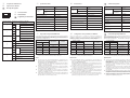
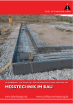
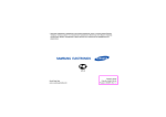
Grounding
쎲
쎲
Applicable PLC
The FX2NC-ENET-ADP can be used in combination with a PLC of the MELSEC
FX1S or FX1N series. For the connection to the PLC base unit, a communication
adapter FX1N-CNV-BD is required.
For further information of installation arrangements, please refer to the Hardware Manual of the FX1S or FX1N series.
쎲
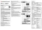
Connection to the PLC
The grounding resistance should be 100 액 or less.
The grounding point should be close to the PLC. Keep the grounding
wires as short as possible.
Independent grounding should be performed for best results. When
independent grounding is not performed, perform "shared grounding"
of the following figure
PLC
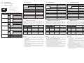
햲 Turn off the power.
햳 Remove the cover (right fig. "A") as
shown in the right figure.
햴 Remove the cover (right fig. "B") from the
base unit.
햵 Install the FX1N-CNV-BD (right fig. "C") to
the base unit.
햶 Fix the FX1N-CNV-BD to the base unit
using the M3 screws provided with the
board. The tightening torque is 0.3 to
0.6 Nm.
Independent grounding
Best condition
C 햶
햶
D
PLC
Other
equipment
PLC
Other
equipment
A
햳
B
Other
equipment
쎲
X3
X1
햵
Y0
Y2
Y1
쎲
Shared grounding
Good condition
Common grounding
Not allowed
For grounding the FX2NC-ENET-ADP use wires with a size from 1 to
2 mm2.
Tighten the screws of the terminal block with a torque of 0.4 to 0.5 Nm.
Wiring example
햴
Grounding (100 액 or less)
햷 Connect the extension cable of the FX2NC-ENET-ADP to the FX1N-CNV-BD
(above fig. "D").
To Hub
Mounting
The FX2NC-ENET-ADP can be mounted with
M4 screws by using the two direct mounting
holes. Use 2 sets of a screw, a spring washer,
and a flat washer. The tightening torque is 0.7
to 1.0 Nm.
For the pitch and position of the mounting
holes, please refer to the figure with the external dimensions.
FX1S/FX1N
ENET
-ADP
Screws
The FX2NC-ENET-ADP can also be mounted on
a DIN rail (DIN46227, 35 mm width).
DIN rail
ENET-ADP
FX1S/FX1N
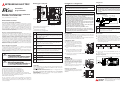
MITSUBISHI
ELECTRIC
FACTORY AUTOMATION
Mitsubishi Electric Europe B.V. /// FA - European Business Group ///
Germany /// Tel.: +49(0)2102-4860 /// Fax: +49(0)2102-4861120 ///
www.mitsubishi-automation.com
Abmessungen und Bedienelemente
POWER
ACT
SD
RD
Installationsanleitung für ETHERNETAdapter FX2NC-ENET-ADP
�
�
Art.-Nr.: 160241 GER, Version A, 22092009
E
쐈
�
�
Sicherheitshinweise
19,1
Bestimmungsgemäßer Gebrauch
7
쐅
74
Nur für qualifizierte Elektrofachkräfte
Diese Installationsanleitung richtet sich ausschließlich an anerkannt ausgebildete Elektrofachkräfte, die mit den Sicherheitsstandards der Elektro- und Automatisierun gstech n ik vertraut s in d. P r o j e k t i e r u n g , I n s t a l l a t i o n ,
Inbetriebnahme, Wartung und Prüfung der Geräte dürfen nur von einer anerkannt ausgebildeten Elektrofachkraft durchgeführt werden. Eingriffe in die
Hard- und Software unserer Produkte, soweit sie nicht in dieser Installationsanleitung oder anderen Handbüchern beschrieben sind, dürfen nur durch unser
Fachpersonal vorgenommen werden.
78
Gewicht: 0.1 kg
Alle Abmessungen sind in der Einheit „mm“ angegeben.
� Abstand der Befestigungsbohrung
� Abstand zwischen den Befestigungsbohrungen
� Abstand zur Mitte der DIN-Schiene
Die speicherprogrammierbaren Steuerungen (SPS) der MELSEC FX1S-, FX1Nund FX2NC-Serie sind nur für die Einsatzbereiche vorgesehen, die in der vorliegenden Installationsanleitung oder den unten aufgeführten Handbüchern
beschrieben sind. Achten Sie auf die Einhaltung der in den Handbüchern angegebenen allgemeinen Betriebsbedingungen. Die Produkte wurden unter
Beachtung der Sicherheitsnormen entwickelt, gefertigt, geprüft und dokumentiert. Unqualifizierte Eingriffe in die Hard- oder Software bzw. Nichtbeachtung der in dieser Installationsanleitung angegebenen oder am Produkt
angebrachten Warnhinweise können zu schweren Personen- oder Sachschäden führen. Es dürfen nur von MITSUBISHI ELECTRIC empfohlene Zusatz- bzw.
Erweiterungsgeräte in Verbindung mit den speicherprogrammierbaren Steuerungen der MELSEC FX-Familie verwendet werden. Jede andere darüber hinausgehende Verwendung oder Benutzung gilt als nicht bestimmungsgemäß.
Nr.
Beschreibung
�
Befestigungsbohrung
Zwei Bohrungen (∅ 4,2 mm) für M4-Schrauben zur Befestigung des
Moduls, wenn keine DIN-Schiene verwendet wird.
Sicherheitsrelevante Vorschriften
쐏
ACT LED (rot)
Leuchtet, wenn über das angeschlossene Ethernet-Netzwerk Daten
ausgetauscht werden.
쐄
SD-LED
Diese LED leuchtet, wenn Daten an die angeschlossene SPS gesendet werden. (siehe auch Abschnitt „Einstellung der Ethernet-Parameter“.)
Bei der Projektierung, Installation, Inbetriebnahme, Wartung und Prüfung der
Geräte müssen die für den spezifischen Einsatzfall gültigen Sicherheits- und
Unfallverhütungsvorschriften beachtet werden.
In dieser Installationsanleitung befinden sich Hinweise, die für den sachgerechten und sicheren Umgang mit dem Gerät wichtig sind. Die einzelnen Hinweise
haben folgende Bedeutung:
P
E
Weitere Informationen
Die folgenden Handbücher enthalten weitere Informationen:
쎲 Hardware-Beschreibung zur MELSEC FX1S-Serie
쎲 Hardware-Beschreibung zur MELSEC FX1N-Serie
쎲 Programmieranleitung zur MELSEC FX-Familie
쎲 Bedienungsanleitung zur Konfigurations-Software FX Configurator-EN
쎲 Installationsanleitung zum Kommunikationsadapter FX1N-CNV-BD
Diese Handbücher stehen Ihnen im Internet kostenlos zur Verfügung
(www.mitsubishi-automation.de).
Sollten sich Fragen zur Installation, Programmierung und Betrieb der in dieser
Installationsanleitung beschriebenen Geräte ergeben, zögern Sie nicht, Ihr
zuständiges Verkaufsbüro oder einen Ihrer Vertriebspartner zu kontaktieren.
E
GEFAHR
Schalten Sie vor der Installation und der Verdrahtung die Versorgungsspannung der SPS und andere externe Spannungen aus.
�
�
�
LINK
�
P
�
65,5 �
Speicherprogrammierbare
Steuerungen
�
45 �
FX2NC-ENET-ADP
Verdrahtung
Installation und Verdrahtung
10 �
16,1
�
90
MITSUBISHI ELECTRIC
�
POWER-LED (grün):
Diese LED leuchtet, wenn von der SPS eine Spannung von 5 V DC
zur Verfügung gestellt wird.
쐋
LINK LED (grün)
Diese LED leuchtet, wenn das FX2NC-ENET-ADP an einem Hub
angeschlossen und die Spannung eingeschaltet ist.
ACHTUNG
쎲 Betreiben Sie die Module nur unter den Umgebungsbedingungen, die
in der Hardware-Beschreibung zur FX1S- oder FX1N-Serie aufgeführt
sind. Die Module dürfen keinem Staub, Ölnebel, ätzenden oder entzündlichen Gasen, starken Vibrationen oder Schlägen, hohenTemperaturen und keiner Kondensation oder Feuchtigkeit ausgesetzt
werden.
Systemkonfiguration
FX2NC-ENET-ADP
FX1S/FX1N
PC
FX2NC-ENET-ADP
FX1S/FX1N
....
쎲 Entfernen Sie nach der Installation die Schutzabdeckung von den Lüftungsschlitzen der Module. Wenn dies nicht beachtet wird, können
Brände, Geräteausfälle oder Fehler auftreten.
�
쎲 Berühren Sie keine spannungsführenden Teile der Module, wie z. B.
die Anschlussklemmen oder Steckverbindungen.
�
Hub
쎲 Befestigen Sie die Module sicher auf einer DIN-Schiene oder mit
Schrauben.
Nr.
Beschreibung
쎲 Installieren Sie die SPS auf einen ebenen Untergrund, um ein Verspannen zu vermeiden.
�
LAN-Kabel
Abgeschirmte Kabel mit paarig verdrillten Leitern (STP-Leitungen)
der Kategorie 5e, 5 oder 3 (nicht gekreuzt)
쎲 Befestigen Sie das Erweiterungs- und das Kommunikationskabel
sicher am entsprechenden Stecker. Unzureichende Verbindungen
können zu Funktionsstörungen führen.
Erdung
Verwendbare SPS
Das FX2NC-ENET-ADP kann mit einer SPS der MELSEC FX1S- oder FX1N-Serie
kombiniert werden. Zum Anschluss an das SPS-Grundgerät ist ein Kommunikationsadapter FX1N-CNV-BD erforderlich.
Weitere Informationen zur Installation der Module enthält die Hardware-Beschreibung zur MELSEC FX1S- oder FX1N-Serie.
쎲
쎲
쎲
Der Erdungswiderstand darf max. 100 액 betragen.
Der Anschlusspunkt sollte so nah wie möglich an der SPS sein. Die Drähte
für die Erdung sollten so kurz wie möglich sein.
Die SPS sollte nach Möglichkeit unabhängig von anderen Geräten geerdet werden. Sollte eine eigenständige Erdung nicht möglich sein, ist eine
gemeinsame Erdung entsprechend dem mittleren Beispiel in der folgenden Abbildung auszuführen.
Anschluss an die SPS
햲 Schalten Sie die Versorgungsspannung aus.
햳 Entfernen Sie, wie in der nebenstehenden Abbildung gezeigt, die Abdeckung
(„A“ in der Abb. rechts) vom Grundgerät.
햴 Entfernen Sie die Abdeckung ("B") vom
Grundgerät.
햵 Installieren Sie das FX1N-CNV-BD ("C") in
das Grundgerät.
햶 Befestigen Sie das FX1N-CNV-BD mit den
zwei mitgelieferten M3-Schrauben. Das
Anzugsmoment beträgt 0,3 bis 0,6 Nm.
쐂
�
Erweiterungskabel zum Anschluss an das SPS-Grundgerät
�
RJ45-Buchse
Zum Anschluss an das Ethernet
Montage
쐎
Klemmenblock für die Erdung (Die drei Anschlüsse sind intern miteinander verbunden.)
쐅
Montagelasche für DIN-Schiene
쐈
Aussparung für DIN-Schienenmontage (DIN 46277)
Das FX2NC-ENET-ADP kann mit Hilfe von zwei
M4-Schrauben und den Befestigungslöchern
direkt montiert werden. Verwenden Sie
jeweils eine Schraube, eine Federscheibe und
eine Unterlegscheibe. Das Anzugsmoment
beträgt 0,7 bis 1,0 Nm.
Die Abstände und die Position der Befestigungsbohrungen entnehmen Sie bitte der
Abbildung mit den Abmessungen.
FX2NC-ENET-ADP, die vom 1. April 2004 bis zum 30. April 2006 hergestellt wurden, entsprechen den EU-Richtlinien EN61000-6-4, EN61131-2:1994 +
A11:1996 + A12:2000 und EN61000-6-2.
FX2NC-ENET-ADP, die ab dem 1. Mai 2006 hergestellt wurden, entsprechen der
EU-Richtlinie EN61131-2:2003.
Hinweis zur Konformität mit den EU-Richtlinien zur elektromagnetischen
Verträglichkeit
Ein FX2NC-ENET-ADP muss in ein abgeschirmtes Gehäuse aus Metall, wie z. B.
einem Schaltschrank, montiert werden.
쎲 Befestigen Sie das ETHERNET-Kabel so, dass auf dem Stecker kein
direkter Zug ausgeübt wird.
쎲 Achten Sie bei der Montage darauf, dass keine Bohrspäne oder Drahtreste durch die Lüftungsschlitze in das Modul gelangen. Das kann
Brände, Geräteausfälle oder Fehler verursachen.
RD-LED
Leuchtet, wenn Daten von der angeschlossenen SPS empfangen
werden. (siehe auch Abschnitt „Einstellung der EthernetParameter“.)
Konformität
ACHTUNG
쎲 Verlegen Sie Signalleitungen nicht in der Nähe von Netz- oder Hochspannungsleitungen oder Leitungen, die eine Lastspannung führen.
Der Mindestabstand zu diesen Leitungen beträgt 100 mm. Wenn dies
nicht beachtet wird, können durch Störungen Fehlfunktionen
auftreten.
SPS
A
햳
Unabhängige Erdung
Beste Lösung
C 햶
햶
B
D
Sonstige
Geräte
SPS
Sonstige
Geräte
Gemeinsame Erdung
Gute Lösung
SPS
Sonstige
Geräte
Gemeinsame Erdung
Nicht erlaubt
X3
X1
쎲
햵
Y0
Y2
Y1
햴
쎲
햷 Schließen Sie das Erweiterungskabel des FX 2NC-ENET-ADP an das
FX1N-CNV-BD an ("D" in der Abbildung oben).
FX1S/FX1N
Verwenden Sie zur Erdung des FX2NC-ENET-ADP Drähte mit einem Querschnitt von 1 bis 2 mm2.
Ziehen Sie die Schrauben des Klemmenblocks mit einem Moment von
0,4 bis 0,5 Nm an.
Anschlussbeispiel
Erdung (Erdungswiderstand 울100 액)
Zum Hub
ENET
-ADP
Schrauben
Das FX2NC-ENET-ADP kann auch auf einer
DIN-Schiene nach DIN46227 mit einer Breite
von 35 mm montiert werden.
DINSchiene
ENET-ADP
FX1S/FX1N
MITSUBISHI
ELECTRIC
FACTORY AUTOMATION
Mitsubishi Electric Europe B.V. /// FA - European Business Group ///
Germany /// Tel.: +49(0)2102-4860 /// Fax: +49(0)2102-4861120 ///
www.mitsubishi-automation.com
Dimensions et éléments de commande
�
POWER
LINK
�
ACT
SD
RD
Carte ETHERNET FX2NC-ENET-ADP
– Manuel d’installation
�
�
�
�
�
E
쐈
�
N° arti : 160241 FRA, Version A, 22092009
�
Informations de sécurité
19,1
7
쐅
74
Groupe cible
Ce manuel est destiné uniquement à des électriciens qualifiés et ayant reçus
une formation reconnue par l'état et qui se sont familiarisés avec les standards
de sécurité de la technique d'automatisation. Tout travail avec le matériel
décrit, y compris la planification, l'installation, la configuration, la maintenance,
l'entretien et les tests doit être réalisé uniquement par des électriciens formés
et qui se sont familiarisés avec les standards et prescriptions de sécurité de la
technique d'automatisation applicable.
78
Poids: 0,1 kg
Toutes les dimensions sont en "mm".
� Cote jusqu’au trou de vis.
� Entr’axes des trous de vis.
� Cote jusqu’à l’axe du profilé DIN.
Utilisation correcte
Les automates programmables MELSEC FX1S, FX1N et FX2NC sont prévus
uniquement pour les applications explicitement décrites dans ce manuel ou
répertoriées ci-dessous. Veuillez prendre soin de respecter tous les paramètres
d'installation et de fonctionnement spécifiés dans le manuel. Tous les produits
ont été développés, fabriqués, contrôlés et documentés en respectant les
normes de sécurité. Toute modification du matériel ou du logiciel ou le
non-respect des avertissements de sécurité indiqués dans ce manuel ou placés
sur le produit peut induire des dommages importants aux personnes ou au
matériel ou à d'autres biens. Seuls les accessoires et appareils périphériques
recommandés par MITSUBISHI ELECTRIC doivent être utilisés. Tout autre
emploi ou application des produits sera considéré comme non conforme.
N°.
Description
�
Alésage de fixation :
2 trous d'un diamètre de 4,5 mm (vis M4) pour la fixation du
module si aucun rail DIN n'est utilisé.
�
DEL POWER (verte) :
Cette DEL est allumée lorsqu'une tension de 5 V CC est mise à disposition par l'API.
�
LINK LED (liaison – verte) :
allumée lorsque l’adaptateur FX2NC-ENET-ADP est connecté au
concentrateur et que l’appareil est alimenté.
쐏
ACT LED (transfert - rouge) :
allumée pendant le transfert de données sur le réseau Ethernet
connecté.
쐄
SD LED (envoi – rouge) :
allumée lors de l’envoi de données à l’automate programmable
connecté. (Voir également “paramétrage Ethernet”.)
쐂
RD LED (réception - rouge) :
allumée lors de la réception de données en provenance de l’automate programmable connecté. (Voir également “paramétrage
Ethernet”.)
Prescriptions de sécurité importantes
Toutes les prescriptions de sécurité et de prévention d'accident importantes
pour votre application spécifique doivent être respectées lors de la planification, l'installation, la configuration, la maintenance, l'entretien et les tests de
ces produits.
Dans ce manuel, les avertissements spéciaux importants pour l'utilisation correcte et sûre des produits sont indentifiés clairement comme suit :
P
�
E
Autres informations
Les manuels suivants comportent d'autres informations sur les modules :
쎲 Manuel d’utilisation du matériel FX1S
쎲 Manuel d’utilisation du matériel FX1N
쎲 Série FX3G/FX3U/FX3UC – Manuel de programmation
쎲 Instructions de service du logiciel de configuration FX Configurator-EN
쎲 Carte de communication FX1N-CNV-BD – Manuel d’installation
Ces manuels sont disponibles gratuitement sur
(www.mitsubishi-automation.fr).
Si vous avez des questions concernant la programmation et le fonctionnement
du matériel décrit dans ce manuel, contactez votre bureau de vente responsable ou votre distributeur.
E
DANGER
Câble d’extension :
utilisé pour connecter le châssis de base
쐊
Prise femelle RJ45
Utilisé pour connecter le câble Ethernet.
쐎
Bornier de raccordement à la masse
(les 3 bornes sont connectées à l’intérieur).
쐅
Collier de montage pour rail DIN
쐈
Rainure pour le montage sur rail DIN (rail DIN : DIN46277)
ATTENTION
쎲 Fixez le câble ETHERNET de telle sorte qu'aucune force de traction
directe ne puisse être exercée sur le connecteur.
쎲 Utilisez les modules uniquement sous les conditions ambiantes mentionnées dans le manuel du matériel de la série FX1S ou FX1N. Les
modules ne doivent pas être exposés à des poussières conductrices,
vapeurs d'huile, gaz corrosifs ou inflammables, de fortes vibrations
ou secousses, des températures élevées, de la condension ou de
l'humidité.
Configuration du système
FX2NC-ENET-ADP
FX1S/FX1N
PC
쎲 Faites attention lors du montage à ce qu'aucun copeau de forage ou
reste de câble ne pénètre dans les fentes d'aération, cela pourrait
sinon provoquer un court-circuit.
FX2NC-ENET-ADP
FX1S/FX1N
....
쎲 Retirez après l'installation le capot de protection des grilles d'aération des modules. Si cela n'est pas effectué, des incendies, des pannes
des appareils ou des défauts peuvent apparaître.
�
쎲 Ne pas toucher les parties du module sous tension comme par ex. les
bornes ou les fiches de raccordement.
Hub
�
쎲 Fixez les modules fiablement sur un rail DIN ou avec des vis.
쎲 Installez l'API sur un fond plan pour éviter un gauchissement.
N°.
Description
쎲 Fixez le câble d'extension et de communication correctement sur le
connecteur correspondant. Des connexions insuffisantes peuvent
entraîner des perturbations fonctionnelles.
�
Câble réseau
Câble à paires torsadées (STP) Catégorie 5e, 5 ou 3 (câble droit)
API utilisable
Mise à la terre
Le module FX2NC-ENET-ADP peut s’utiliser avec un automate programmable
MELSEC FX1S FX1N. Pour la connexion au châssis de base de l’automate programmable, une carte de communication FX1N-CNV-BD est indispensable.
Pour plus d’informations sur les dispositions de montage, voir le Manuel d’utilisation du matériel FX1S ou FX1N.
쎲
쎲
쎲
Connexion à l’automate programmable
햲 Débranchez la tension d'alimentation.
햳 Déposez le cache (à droite fig. "A", voir
illustration à droite).
햴 Déposez le cache (à droite fig. "B") du
châssis de base.
햵 Montez le FX1N-CNV-BD (à droite fig. "C")
sur le châssis de base.
햶 Fixez le FX1N-CNV-BD sur le châssis de base
à l’aide des vis M3 fournies avec la carte. Le
couple de serrage est de 0,3 à 0,6 Nm.
La résistance de mise à la terre doit être de maximum 100 액.
Le point de raccordement doit être aussi proche que possible de l'API. Les
conducteurs pour la mise à la terre doivent être aussi courts que possible.
L'API doit si possible être mis à la terre indépendamment des autres
appareils. Si une mise à la terre indépendante n'est pas possible, une mise
à la terre commune doit être réalisée selon l'exemple du milieu de la
figure suivante.
A
햳
API
Appareils
divers
API
Appareils
divers
API
Appareils
divers
C 햶
햶
B
D
Mise à la terre indépendante
La solution la meilleure
X3
X1
햵
햴
Y0
Y
Y1
쎲
쎲
햷 Connectez le câble d‘extension du FX2NC-ENET-ADP au FX1N-CNV-BD
(ci-dessus fig. "D").
Mise à la terre commune
Bonne solution
Mise à la terre commune
Non autorisé
Pour le raccordement à la masse, le FX2NC-ENET-ADP utilise des câbles de
section 1 à 2 mm2.
Serrez les vis des bornes à un couple compris entre 0,4 et 0,5 N.m.
Exemple de câblage
Mise à la terre (résistance de mise à la
terre maximale de 100 Ω )
Montage
Le module FX2NC-ENET-ADP peut se monter
avec des vis M4 en utilisant les 2 trous de fixation directe. Utilisez 2 jeux : une vis, une rondelle élastique et une rondelle plate. Le couple
de serrage est de 0,7 à 1,0 Nm.
Pour la position des trous de montage, voir la
figure indiquant les cotes extérieures.
FX1S/FX1N
Vers le concentrateur
ENET
-ADP
Vis
Conformité
Le module FX2NC-ENET-ADP fabriqué entre le 1er avril 2004 et le 30 avril 2006
est conforme aux normes EN61000-6-4, EN61131-2:1994+A11:1996+A12:2000
et EN61000-6-2.
Le module FX2NC-ENET-ADP fabriqué après le 1er mai 2006 est conforme à la
norme EN61131-2:2003.
Note sur la conformité aux réglementations CEM
Le module FX2NC-ENET-ADP doit être installé dans un boîtier de commande
métallique blindé.
ATTENTION
쎲 Ne pas poser des câbles de signaux à proximité de câbles du secteur et
de câbles à haute tension ou de câbles parcourus par une tension en
décharge. L'écart minimal avec ces câbles est de 100 mm. Des défaillances dues à des perturbations peuvent apparaître si cet écart n'est
pas respecté. Si cela n'est pas respecté, des dysfonctionnements dus à
des défaillances peuvent apparaître.
Déconnectez avant l'installation ou le câblage, toutes les phases de la
tension d'alimentation de l'API et autres tensions externes
65,5 �
Automates
programmables
P
�
45 �
FX2NC-ENET-ADP
Câblage
Installation et câblage
10 �
16,1
�
90
MITSUBISHI ELECTRIC
Le FX 2NC -ENET-ADP peut également être
monté sur un rail DIN selon DIN46227 d'une
largeur de 35 mm.
Rail DIN
ENET-ADP
FX1S/FX1N
MITSUBISHI
ELECTRIC
FACTORY AUTOMATION
Mitsubishi Electric Europe B.V. /// FA - European Business Group ///
Germany /// Tel.: +49(0)2102-4860 /// Fax: +49(0)2102-4861120 ///
www.mitsubishi-automation.com
m
D
F
m
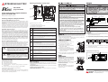
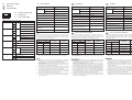
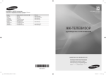
Pin Configuration
Belegung der Schnittstelle
D
Specifications
Item
Description
Affectation de l'interface
Merkmal
Voltage
5 V DC (supplied from the PLC)
Current consumption
135 mA
Power supply
m
D
F
RJ45 type modular jack
Transmission rate
10 Mbps
RJ45-Buchse
Communication method
Full-duplex
Prise femelle RJ45
Protocol
1
2
3
4
5
6
7
8
Description / Beschreibung / Description
m
D
F
m
D
F
m
D
F
m
D
F
m
D
F
m
D
F
TD+
Spannungsversorgung
Beschreibung
Spannung
Stromaufnahme
135 mA
Number of simultaneously open connections
max. 1
Sendedaten (+)
No. of FX2NC-ENET-ADP in one PLC
max. 1
Données à transmettre (+)
Occupied I/O points
0
5 V CC (Alimentation par l’API)
Consommation
de courant
135 mA
10 Mbit/s
Vitesse de transmission
10 Mbit/s
Übertragungsmethode
Voll-Duplex
Méthodes de transmission
duplex intégral
Protokoll
CSMA/CD(IEEE802.3)
Protocole
CSMA/CD(IEEE802.3)
Schnittstelle
10BASE-T
Interface
10BASE-T
Netzwerk-Topologie
Stern
Topologie
Étoile
Anzahl der gleichzeitig geöffneten Verbindungen
max. 1
Nombre de connexions ouvertes simultanément
maxi. 1
Anzahl FX2NC-ENET-ADP in einer SPS
max. 1
Nombre FX2NC-ENET-ADP dans un API
maxi. 1
Belegte E/A-Adressen
0
Adresses E/S affectées
0
Star typ
Transmit-Data (+)
Alimentation
en courant
Description
Tension d'alimentation
Übertragungsgeschwindigkeit
10BASE-T
Topology
Caractéristiques techniques
Caractéristiques
5 V DC
(Versorgung durch die SPS)
CSMA/CD(IEEE802.3)
Interface
Pin / Pin / Broche
F
Technische Daten
Transmit-Data (–)
TD–
Sendedaten (–)
Données à transmettre (–)
Receive-Data (+)
RD+
Empfangsdaten (+)
m
D
Ethernet Parameter Setting
Use the PLC program or file registers to write the Ethernet parameters to data
registers in the PLC. Immediately after the power is switched on, the
FX2NC-ENET-ADP reads the parameters stored in the data registers and
configures itself.
Données à recevoir (+)
Datenregister
Data register
Setting item
Not used
FX1S
F
Einstellung der Ethernet-Parameter
Verwenden Sie das SPS-Programm oder File-Register, um die Ethernet-Parameters in Datenregister der SPS einzutragen. Unmittelbar nach dem Einschalten
der Versorgungsspannung liest das FX2NC-ENET-ADP die in den Datenregistern gespeicherten Parameter und konfiguriert sich selbst.
Einstellung
Default parameter
FX1S
FX1N*
FX1N*
Paramétrage Ethernet
Utilisez le programme de l’automate programmable ou les registres fichiers pour
inscrire les paramètres dans les registres de données de l’automate programmable. Immédiatement après la mise sous tension, le FX2NC-ENET-ADP lit les
paramètres enregistrés dans les registres de données et se configure lui-même.
Registre de données
Voreingestellte
Parameter
Paramètre
FX1S
FX1N*
Paramètre par
défaut
Nicht belegt
D128, D129 D쏔000, D쏔001
Header
—
D128, D129 D쏔000, D쏔001
Header
—
D128, D129 D쏔000, D쏔001
En-tête
—
Non affecté
D130, D131 D쏔002, D쏔003
IP address
192.168.0.100
D130, D131 D쏔002, D쏔003
IP-Adresse
192.168.0.100
D130, D131 D쏔002, D쏔003
Adresse IP
192.168.0.100
Receive-Data (–)
D132, D133 D쏔004, D쏔005
Subnet mask
255.255.255.0
D132, D133 D쏔004, D쏔005
Subnet-Maske
255.255.255.0
D132, D133 D쏔004, D쏔005
Masque de sous-réseau
255.255.255.0
Empfangsdaten (–)
D134, D135 D쏔006, D쏔007
Gateway address
192.168.0.1
D134, D135 D쏔006, D쏔007
Gateway-Adresse
192.168.0.1
TCP port number
1024
TCP-Port-Nummer
1024
RD–
Données à recevoir (–)
Not used
D136
D쏔008
* "쏔" represents any number in the range from 1 to 7. Use nine consecutive
data registers, e.g. D1000 to D1008, D2000 to D2008 etc.
D136
D쏔008
* „쏔“ steht für eine Ziffer im Bereich von 1 bis 7. Verwenden Sie neun aufeinander folgende Datenregister, z. B. D1000 bis D1008, D2000 bis D2008 etc.
Nicht belegt
Non affecté
Notes
Hinweise
쎲
쎲
쎲
쎲
쎲
The header is used by the FX2NC-ENET-ADP to identify the Ethernet
parameters. Make sure to set 454E4554H ("ENET") to D128/D129 resp.
D쏔000/D쏔001.
For FX1N only: The FX2NC-ENET-ADP searches for the header in the order
D1000 -> D7000. The contents of the lowest data numbers are used as the
Ethernet parameters.
If "ENET" is not found or a parameter such as IP address or Gateway
address is incorrect, the default parameters are valid. In this case, the RD
LED is lit.
If the FX2NC-ENET-ADP can not read out the contents of the data registers
containing the Ethernet parameters, the default parameters are used. In
this case, the SD LED is lit.
The settings of IP address, Subnet mask and Gateway address depend on
the network enviroment. For the contents of these parameters, see the
network administrator.
쎲
쎲
쎲
Der Header wird vom FX2NC-ENET-ADP zum identifizieren der Ethernet-Parameter verwendet. Tragen Sie in D128/D129 bzw. D쏔000/
D쏔001 unbedingt den Wert 454E4554H („ENET“) ein.
Nur für FX1N: Das FX2NC-ENET-ADP sucht den Header in der Reihenfolge
D1000 -> D7000. Die Inhalte der Register mit den niedrigsten Adressen
werden als Ethernet-Parameter verwendet.
Wird "ENET" nicht gefunden oder ist ein Parameter wie z. B. die IP-Adresse
oder die Gateway-Adresse nicht korrekt, werden die voreingestellten
Parameter verwendet. In diesem Fall leuchtet die RD-LED.
Wenn das FX2NC-ENET-ADP die Inhalte der Datenregister mit den Ethernet-Parametern nicht lesen kann, werden die voreingestellten Parameter
verwendet. In diesem Fall leuchtet die SD-LED.
Die Einstellung der IP-Adresse, der Subnet-Maske und der Gateway-Adresse hängt von der Netzwerkumgebung ab. Stimmen Sie die
Einstellung dieser Parameter mit dem Netzwerk-Administrator ab.
D134, D135 D쏔006, D쏔007 Adresse de la passerelle
D136
D쏔008
Numéro du port TCP
192.168.0.1
1024
* "쏔" indique un nombre compris entre 1 et 7. Utilisez 9 registres de données
adjacents (ex. D1000 à D1008, D2000 à D2008, etc.)
Remarques
쎲
쎲
쎲
쎲
Le FX2NC-ENET-ADP utilise l’en-tête pour identifier les paramètres Ethernet. N’oubliez pas de configurer 454E4554H (“ENET”) avec D128/D129
(resp. Dl000/Dl001).
Pour l’automate programmable FX 1N uniquement : le module
FX2NC-ENET-ADP recherche l’en-tête dans l’ordre suivant :
D1000 -> D7000. Le contenu des numéros inférieurs est utilisé pour les
paramètres Ethernet.
Si "ENET" est introuvable ou si un paramètre tel que l’adresse IP ou l’adresse de la passerelle est incorrect, les paramètres par défaut s’appliquent. Dans ce cas, la DEL RD est allumée.
Si le module FX2NC-ENET-ADP ne peut pas lire le contenu des registres de
données qui contiennent les paramètres Ethernet, les paramètres par
défaut sont utilisés. Dans ce cas, la DEL SD est allumée.
L’adresse IP, le masque de sous-réseau et l’adresse de la passerelle dépendent de l’environnement réseau. Pour la valeur de ces paramètres, voir
votre administrateur réseau.
Dimensioni e comandi
16.1 �
POWER
LINK
�
ACT
SD
RD
Manuale d’installazione per l’adattatore
ETHERNET FX2NC-ENET-ADP
�
�
�
�
�
E
쐈
�
Art-no.: 160241 ITA, Version A, 20122009
�
Avvertenze di sicurezza
19.1
쐅
Solo per personale elettrico qualificato
Il presente manuale d'installazione si rivolge esclusivamente a personale
elettrico specializzato e qualificato, a perfetta conoscenza degli standard di
sicurezza elettrotecnica e di automazione. La progettazione, l'installazione, la
messa in funzione, la manutenzione e il collaudo degli apparecchi possono
essere effettuati solo da personale elettrico specializzato e qualificato. Gli
interventi al software e hardware dei nostri prodotti, per quanto non illustrati
nel presente manuale d'installazione o in altri manuali, possono essere eseguiti
solo dal nostro personale specializzato.
Impiego conforme alla destinazione d'uso
I controllori programmabili (PLC) della serie MELSEC FX1S, FX1N e FX2NC sono
previsti solo per i settori d’impiego descritti nel presente manuale
d’installazione o nei manuali in seguito indicati.. Abbiate cura di osservare le
condizioni generali di esercizio riportate nei manuali. I prodotti sono stati
progettati, realizzati, collaudati e documentati nel rispetto delle norme di
sicurezza. Interventi non qualificati al software o hardware ovvero
l'inosservanza delle avvertenze riportate nel presente manuale d'installazione
o delle insegne di segnalazione applicate sul prodotto possono causare danni
seri a persone o cose. Con i controllori programmabili della famiglia MELSEC FX
si possono utilizzare solo unità aggiuntive o di espansione consigliate da
MITSUBISHI ELECTRIC. Ogni altro utilizzo o applicazione che vada oltre quanto
illustrato è da considerarsi non conforme.
Norme rilevanti per la sicurezza
Nella progettazione, installazione, messa in funzione, manutenzione
e collaudo delle apparecchiature si devono osservare le norme di sicurezza
e prevenzione valide per il caso d'utilizzo specifico.
Nel presente manuale d'installazione troverete indicazioni importanti per una
corretta e sicura gestione dell'apparecchio. Le singole indicazioni hanno il
seguente significato:
P
E
PERICOLO
ATTENZIONE
7
74
78
Peso: 0,1 kg
Tutte le dimensioni sono espresse in "mm".
� Distanza del foro di fissaggio
� Distanza fra i fori di fissaggio
� Distanza dal centro della guida DIN
Rif.
Descrizione
�
Foro di fissaggio
Due fori (∅ 4,5 mm) per viti M4 per il fissaggio del modulo, qualora
non si utilizzi una guida DIN.
�
LED POWER (verde):
questo LED è acceso, quando dal PLC viene resa disponibile una
tensione di 5 V DC
�
LINK LED (verde)
Questo LED si accende quando l’adattatore FX2NC-ENET-ADP è
collegato ad un Hub e la tensione è inserita.
쐏
ACT LED (rosso)
È acceso quando attraverso la rete Ethernet collegata vengono
scambiati dati.
쐄
SD-LED
Questo LED è acceso quando i dati vengono inviati al PLC collegato.
(vedi anche il capitolo "Impostazione dei parametri Ethernet".)
쐂
RD-LED è acceso quando i dati vengono ricevuti dal PLC collegato.
(vedi anche il capitolo "Impostazione dei parametri Ethernet".)
�
Cavo di espansione per il collegamento all’unità PLC base
쐊
Connettore RJ45:
Per il collegamento a Ethernet
쐎
Morsettiera di messa a terra (internamente i tre morsetti sono
collegati fra loro.)
Conformità
Ulteriori informazioni
Il seguente manuale contiene ulteriori informazioni:
쎲 Descrizione dell’hardware per la serie MELSEC FX1S
쎲 Descrizione dell’hardware per la serie MELSEC FX1N
쎲 Guida di programmazione per la famiglia MELSEC FX
쎲 Manuale d'uso del software di configurazione FX Configurator-EN
쎲 Manuale d’installazione per l’adattatore di comunicazione FX1N-CNV-BD
Questo manuale è disponibile gratuitamente in Internet
(www.mitsubishi-automation.it).
Nel caso di domande in merito ai lavori di installazione, programmazione
e funzionamento dei controllori della serie MELSEC FX1S, FX1N e FX2NC, non
esitiate a contattare l'Ufficio Vendite di vostra competenza o uno dei partner
commerciali abituali.
E
PERICOLO
Gli FX2NC-ENET-ADP, che sono stati prodotti dal 1° aprile 2004 al 30 aprile 2006,
sono conformi alle direttive UE EN61000-6-4, EN61131-2:1994 + A11:1996 +
A12:2000 und EN61000-6-2.
Gli FX2NC-ENET-ADP, che sono stati prodotti dopo il 1° maggio 2006, sono
conformi alla direttiva UE EN61131-2:2003.
Note sulla conformità alle direttive UE per la compatibilità
elettromagnetica
Un FX2NC-ENET-ADP deve essere montato in una custodia schermata in
metallo, come ad es. un quadro elettrico.
ATTENZIONE
쎲 Non disporre le linee di segnale in prossimità di linee con tensione di
rete o ad alta tensione o di linee conduttive di tensione di carico. La
distanza minima da tali linee è di 100 mm. La mancata osservanza di
tale distanza può causare malfunzionamenti da interferenze.
Prima di procedere all'installazione e al collegamento, disinserire la
tensione di alimentazione al PLC ed altre tensioni esterne.
65.5 �
Controllori
programmabili
P
�
45 �
�
90
FX2NC-ENET-ADP
Collegamento
Installazione e collegamento
10 �
MITSUBISHI ELECTRIC
쎲 Fissare il cavo Ethernet in modo da non esercitare trazione diretta sul
connettore.
ATTENZIONE
쎲 Utilizzare i moduli solo nelle condizioni ambientali riportate nella
Descrizione hardware per la serie FX3UC. Non esporre i moduli a
polvere, nebbia d’olio, gas corrosivi o infiammabili, forti vibrazioni
o urti, temperature elevate, condensa o umidità.
Configurazione del sistema
FX2NC-ENET-ADP
FX1S/FX1N
PC
FX2NC-ENET-ADP
FX1S/FX1N
쎲 Durante il montaggio prestare attenzione affinché attraverso le
fessure di aerazione nell’interno del modulo non penetrino trucioli di
foratura o resti di fili metallici, che in seguito potrebbero causare un
cortocircuito, guasti o malfunzionamento.
....
쎲 Dopo l'installazione rimuovere dalle fessure di aerazione dei moduli
la copertura di protezione. In caso di mancata rimozione possono
verificarsi incendi, guasti all'unità o errori.
�
쎲 Fissare saldamente i moduli su una guida DIN o con viti.
쎲 Installare il PLC su un sottofondo piano, per evitare deformazioni.
쎲 Fissare saldamente tutti i cavi al relativo connettore. Un fissaggio
insufficiente può portare a disturbi di funzionamento.
Rif.
Descrizione
�
Cavo LAN
Cavo schermato con conduttori trefolati a coppie (linee STP) della
categoria 5e, 5 o 3 (non incrociati)
PLC utilizzabili
Messa a terra
L’adattatore FX2NC-ENET-ADP può essere combinato con un PLC della serie
MELSEC FX1S oppure FX1N. Per il collegamento all’unità PLC base è necessario
un adattatore di comunicazione FX1N-CNV-BD.
Per ulteriori informazioni sull’installazione dei moduli consultare la descrizione
dell’hardware relativa alla serie MELSEC FX1S o FX1N.
쎲
쎲
쎲
Collegamento al PLC
햲 Disattivare la tensione di alimentazione.
햳 Come si mostra nella figura qui accanto,
rimuovere il coperchio ("A" nella figura a
destra) dall’unità base.
햴 Rimuovere il coperchio ("B") dall’unità base.
햵 Installare il FX1N-CNV-BD ("C") nell’unità
base
햶 Fissare il FX1N-CNV-BD con le due viti M3
fornite a corredo. Prevedere una coppia
di serraggio compresa tra 0,3 e 0,6 Nm.
�
Hub
쎲 Non toccare alcun componente conduttivo dei moduli, quali ad
esempio i morsetti di collegamento o le spine.
La resistenza di terra può essere pari a max 100 액.
Il punto di collegamento dovrebbe essere più vicino possibile al PLC. I fili
di messa a terra dovrebbero essere i più corti possibile.
Il PLC dovrebbe, se possibile, essere messo a terra separatamente dalle
altre unità. Qualora non fosse possibile procedere a una messa a terra
indipendente, eseguire una messa a terra comune come da esempio al
centro nella figura qui sotto.
A
햳
PLC
Altre unitа
PLC
Altre unitа
PLC
Altre unitа
C 햶
햶
B
D
X3
Messa a terra indipendente
Soluzione migliore
X1
햵
Y0
Messa a terra comune
Soluzione buona
Messa a terra comune
Non consentito
Y2
Y1
햴
쎲
햷 Collegare il cavo di espansione del FX2NC-ENET-ADP al FX1N-CNV-BD
("D" nella figura qui sopra).
쎲
Per la messa a terra del FX2NC-ENET-ADP usare fili con una sezione
da 1 a 2 mm2.
Stringere le viti del morsetto con una coppia di serraggio da 0,4 a 0,5 Nm.
Esempio di collegamento
Messa a terra (max 100 액)
Il FX 2NC -ENET-ADP può essere montato
direttamente per mezzo di due viti M4 e dei
fori di fissaggio. Usare rispettivamente una
vite, una rosetta elastica ed una rondella.
Prevedere una coppia di serraggio compresa
tra 0,7 e 1,0 Nm.
Le distanze e la posizione dei fori di fissaggio
risultano dalla figura con le dimensioni.
FX1S/FX1N
Con l’hub
ENET
-ADP
Viti
Montaggio su una guida DIN
L’FX2NC-ENET-ADP può anche essere montato
su una guida DIN di larghezza 35 mm a norma
DIN46227.
DIN rail
ENET-ADP
FX1S/FX1N
MITSUBISHI
ELECTRIC
FACTORY AUTOMATION
Mitsubishi Electric Europe B.V. /// FA - European Business Group ///
Germany /// Tel.: +49(0)2102-4860 /// Fax: +49(0)2102-4861120 ///
www.mitsubishi-automation.com
Dimensiones y denominación de los
componentes
�
POWER
LINK
�
ACT
SD
�
�
�
�
65,5 �
RD
Instrucciones de instalación para el adaptador de ETHERNET FX2NC-ENET-ADP
�
�
Nro. Art.: 160241 ESP, Versión A, 20122009
Indicaciones de seguridad
Estas instrucciones de instalación están dirigidas exclusivamente a electricistas
profesionales reconocidos que estén perfectamente familiarizados con los
estándares de seguridad de la electrotécnica y de la técnica de automatización.
La proyección, la instalación, la puesta en servicio, el mantenimiento y el
control de los dispositivos tienen que ser llevados a cabo exclusivamente por
electricistas profesionales reconocidos. Manipulaciones en el hardware o en el
software de nuestros productos que no estén descritas en estas instrucciones
de instalación o en otros manuales, pueden ser realizadas únicamente por
nuestros especialistas.
Empleo reglamentario
Los controladores lógicos programables (PLC) de las series FX1S, FX1N y FX2NC
de MELSEC solo están previstos para las áreas de aplicación descritas en las presentes instrucciones de instalación o en los manuales indicados abajo. Hay que
atenerse a las condiciones de operación indicadas en los manuales. Los productos han sido desarrollados, fabricados, controlados y documentados en conformidad con las normas de seguridad pertinentes. Manipulaciones en el
hardware o en el software por parte de personas no cualificadas, así como la no
observación de las indicaciones de advertencia contenidas en estas instrucciones de instalación o colocadas en el producto, pueden tener como consecuencia graves daños personales y materiales. En combinación con los
controladores lógicos programables de la familia FX de MELSEC sólo se permite
el empleo de los dispositivos adicionales o de ampliación recomendados por
MITSUBISHI ELECTRIC. Todo empleo o aplicación distinto o más amplio del indicado se considerará como no reglamentario.
Normas relevantes para la seguridad
Al realizar trabajos de proyección, instalación, puesta en servicio,
mantenimiento y control de los dispositivos, se deben observar las normas de
seguridad y de prevención de accidentes vigentes para la aplicación específica.
En estas instrucciones de instalación hay una serie de indicaciones importantes
para el manejo seguro y adecuado del dispositivo. A continuación se recoge el
significado de cada una de las indicaciones:
19,1
P
E
ATENCIÓN
Advierte de un peligro para el dispositivo u otros aparatos
La no observación de las medidas de seguridad indicadas
puede tener como consecuencia graves daños en el dispositivo o en otros bienes materiales.
Otras informaciones
El siguiente manual contiene más información:
쎲 Descripción de hardware para la serie FX1S de MELSEC
쎲 Descripción de hardware para la serie FX1N de MELSEC
쎲 Instrucciones de programación de la familia FX de MELSEC
쎲 Instrucciones de empleo del software de configuración FX Configurator-EN
쎲 Instrucciones de instalación para el adaptador de comunicación
FX1N-CNV-BD
Este manual está a su disposición de forma gratuita en Internet
(www.mitsubishi-automation.es).
Si se le presentaran dudas acerca de la instalación, programación y la operación
de los controladores de la series FX1S, FX1N y FX2NC de MELSEC, no dude en
ponerse en contacto con su oficina de ventas o con uno de sus vendedores
autorizados.
쐈
�
쐅
7
74
78
Peso: 0,1 kg
Todas las medidas se indican en "mm".
� Distancia del taladro de sujeción
� Distancia entre los taladros de sujeción
� Distancia al centro del carril DIN
N°.
Perforación de fijación
Dos perforaciones (∅ 4,5 mm) para tornillos M4 para la fijación del
módulo en caso de que no se utilice ningún carril DIN.
�
LED POWER (verde):
Este LED se ilumina cuando el PLC pone a disposición una tensión
de 5 V DC.
쐋
LINK LED (verde): Este LED se enciende cuando el FX2NC-ENET-ADP
está conectado a un hub y la tensión está encendida.
쐏
ACT LED (rojo): Se enciende cuando se están intercambiando datos
por vía de la red Ethernet conectada.
쐄
SD-LED: Este LED se enciende cuando se envían datos al PLC
conectado. (Véase también la sección "Configuración de los
parámetros de Ethernet").
쐂
RD-LED: Se enciende cuando se reciben datos del PLC conectado.
(Véase también la sección "Configuración de los parámetros de
Ethernet").
�
Cable de extensión para conectarlo a la unidad base del PLC
�
Hembrilla RJ45:
Para la conexión a Ethernet
쐎
Bloque de bornes para la toma de tierra (las tres conexiones están
interconectadas internamente)
쐅
Brida de montaje para carril DIN
쐈
Escote para el montaje en carril DIN (DIN 46277)
Conformidad
Los FX2NC-ENET-ADP fabricados entre el 01 de abril de 2004 y el 30 de abril de
2006 son conformes con las directivas de la UE EN61000-6-4, EN61131-2:1994 +
A11:1996 + A12:2000 y EN61000-6-2.
Los FX2NC-ENET-ADP fabricados a partir del 01 de mayo de 2006 cumplen la
directiva de la UE EN61131-2:2003.
Indicación sobre la conformidad con las directivas comunitarias sobre la
compatibilidad electromagnética
Un FX2NC-ENET-ADP debe montarse en una carcasa apantallada de metal como
por ej. un armario eléctrico.
ATENCIÓN
쎲 No tienda las líneas de señales en las proximidades de líneas de red o
de alta tensión o de líneas con tensión de trabajo. La distancia
mínima con respecto a ese tipo de líneas tiene que ser de 100 mm. Si no
se tiene en cuenta este punto pueden producirse fallos y disfunciones.
쎲 Fije la línea Ethernet de manera que la clavija no esté sometida a una
tensión directa.
ATENCIÓN
Configuración de sistema
쎲 Haga funcionar los módulos sólo bajo las condiciones ambientales
especificadas en la descripción de hardware de la series FX1S, FX1N y
FX2NC . Los módulos no deben exponerse al polvo, a niebla de aceite, a
gases corrosivos o inflamables, a vibraciones fuertes o a golpes, a
altas temperaturas, a condensación o a humedad.
FX2NC-ENET-ADP
FX1S/FX1N
PC
FX2NC-ENET-ADP
FX1S/FX1N
....
쎲 Al realizar el montaje tenga cuidado de que no entren al interior del
módulo virutas de metal o restos de cables a través de las ranuras de
ventilación. Ello podría causas incendios, defectos o errores en el
dispositivo.
�
쎲 Después de la instalación, retire la cubierta de protección de las ranuras de ventilación de los módulos. Si no se tiene en cuenta este punto
pueden producirse incendios, fallos del aparato y errores.
�
Hub
쎲 No toque ninguna parte del dispositivo que esté sometida a tensión,
como p.ej. los bornes de conexión o las conexiones de enchufe.
N°.
Descripción
쎲 Fije los módulos de forma segura a un carril DIN o con tornillos.
쎲 Instale el PLC sobre una base plana y lisa con objeto de evitar una
deformación del mismo.
�
Cable LAN
Cables apantallados con conductores entrelazados por parejas
(líneas STP) de las categorías 5e, 5 o 3 (sin cruzarlos)
쎲 Fije todos los cables de forma segura a la clavija correspondiente.
Uniones insuficientes pueden provocar disfunciones.
Messa a terra
Descripción
�
PELIGRO
Advierte de un peligro para el usuario
La no observación de las medidas de seguridad indicadas
puede tener como consecuencia un peligro para la vida
o la salud del usuario.
E
�
Sólo para electricistas profesionales debidamente cualificados
E
PELIGRO
Antes de empezar con la instalación y con el cableado hay que desconectar la tensión de alimentación del PLC y otras posibles tensiones
externas.
45 �
FX2NC-ENET-ADP
Controladores
lógicos programables
P
10 �
16,1 �
Cableado
Instalación y cableado
90
MITSUBISHI ELECTRIC
PLCs aplicables
El FX2NC-ENET-ADP se puede combinar con un PLC de las series FX1S o FX1N de
MELSEC. Para la conexión a la unidad base del PLC se necesita un adaptador de
comunicación FX1N-CNV-BD.
Encontrará más información para instalar los módulos en la descripción del
hardware de la serie FX1S o FX1N de MELSEC.
쎲
쎲
쎲
La resistenza di terra può essere pari a max 100 액.
Il punto di collegamento dovrebbe essere più vicino possibile al PLC. I fili
di messa a terra dovrebbero essere i più corti possibile.
Il PLC dovrebbe, se possibile, essere messo a terra separato dalle altre
unità. Qualora non fosse possibile procedere a una messa a terra indipendente, eseguire una messa a terra comune come da esempio al centro
nella figura qui sotto.
Conexión al PLC
햲 Desconecte la tensión de alimentación.
햳 Retire, como se muestra en la figura al
margen, la cubierta ("A" en la figura de la
derecha) de la unidad base.
햴 Retire la cubierta ("B") de la unidad base.
햵 Instale el FX1N-CNV-BD ("C") en la unidad
base.
햶 Fije el FX1N-CNV-BD con los dos tornillos
M3 que vienen incluidos. El par de
apriete de es de entre 0,3 y 0,6 Nm.
PLC
A
햳
햶
D
PLC
Messa a terra indipendente
Soluzione migliore
C 햶
B
Altre unitа
Altre unitа
Messa a terra comune
Soluzione buona
PLC
Altre unitа
Messa a terra comune
Non consentito
X3
X1
쎲
햵
Y0
Y2
Y1
햴
쎲
햷 Conecte el cable de extensión del FX2NC-ENET-ADP al FX1N-CNV-BD
("D" en la figura de arriba).
Para poner a tierra el FX2NC-ENET-ADP utilice alambres con una sección
de 1 a 2 mm2.
Apriete los tornillos de los bloques de bornes con un par de apriete de
0,4 a 0,5 Nm.
Ejemplo de conexión
Messa a terra (max100 액)
Montaje
El FX2NC-ENET-ADP se puede montar directamente mediante los dos tornillos M4 y los orificios de sujeción. Utilice siempre un tornillo,
una arandela elástica y una arandela normal.
El par de apriete de es de entre 0,7 y 1,0 Nm.
Las distancias y la posición de los taladros de
sujeción se pueden consultar en la ilustración
acotada.
FX1S/FX1N
Al hub
ENET
-ADP
Tornillos
El FX2NC-ENET-ADP puede montarse también
en un carril DIN según DIN46227 con un ancho
de 35 mm.
Carril
DIN
ENET-ADP
FX1S/FX1N
MITSUBISHI
ELECTRIC
FACTORY AUTOMATION
Mitsubishi Electric Europe B.V. /// FA - European Business Group ///
Germany /// Tel.: +49(0)2102-4860 /// Fax: +49(0)2102-4861120 ///
www.mitsubishi-automation.com
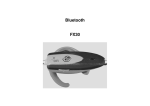
Размеры и элементы управления
16,1 �
POWER
LINK
�
ACT
SD
RD
�
�
�
65,5 �
Программируемые
контроллеры
Руководство по установке адаптера
Ethernet FX2NC-ENET-ADP
�
�
Кат.№.: 160241 RUS, Версия A, 20122009
Указания по безопасности
Использование по назначению
Программируемые контроллеры (ПЛК) серии FX1S, FX1N и FX2NC предназначены только для тех областей применения, которые описаны в данном руководстве по установке или в нижеуказанных руководствах. Обращайте внимание
на соблюдение общих условий эксплуатации, названных в руководствах. Продукция разработана, изготовлена, проверена и задокументирована с соблюдением норм безопасности. Неквалифицированные вмешательства в аппаратуру
или программное обеспечение, либо несоблюдение предупреждений, содержащихся в этом руководстве или нанесенных на саму аппаратуру, могут привести к серьезным травмам или материальному ущербу. В сочетании
с программируемыми контроллерами MELSEC семейства FX разрешается
использовать только аксессуары и модули расширения, рекомендуемые
фирмойMITSUBISHI ELECTRIC. Любое иное использование, выходящие зарамки
сказанного, считается использованием не по назначению.
19,1
P
E
Предупреждение об опасности для пользователя.
Несоблюдение указанных мер предосторожности
может создать угрозу для жизни или здоровья
пользователя.
Предупреждение об опасности для аппаратуры.
Несоблюдение указанных мер предосторожности
может привести к серьезным повреждениям аппаратуры или иного имущества.
Дополнительная информация
Дополнительная информация имеется в следующем руководстве:
쎲 Описание аппаратуры серии FX1S
쎲 Описание аппаратуры серии FX1N
쎲 руководство по программированию MELSEC семейства FX
쎲 Руководство по пользованию программным обеспечением для конфигурирования FX Configurator-EN
쎲 Руководство по установке коммуникационного адаптера FX1N-CNV-BD
Это руководство вы можете бесплатно скачать из интернета по адресу
www.mitsubishielectric.ru.
Е с л и в о з н и к н у т в о п р о с ы по ус т а н о в к е , пр о г р а м м и р о в а н и ю
и эксплуатации контроллеров MELSEC серии FX1S, FX1N и FX2NC, без
колебаний обратитесь в ваше региональное торговое представительство
или к вашему региональному торговому партнеру.
쐈
7
쐅
74
78
Вес: 0,1 kg
Все размеры указаны в "мм".
� Расстояние до крепежного отверстия.
� Расстояние между крепежными отверстиями.
� Расстояние до середины DIN-рейки
쎲 Закрепите провод Ethernet так, чтобы к разъёму не была приложена чрезмерная механическая нагрузка.
ВНИМАНИЕ
쎲 Эксплуатируйте модули только в условиях окружающей
среды, указанных в описании аппаратуры серии FX 1S, FX1N
и FX2NC. Модули не должны быть подвержены воздействию
пыли, масляного тумана, едких или воспламенимых газов, сильной вибрации или ударов, высоких температур и конденсата
или влажности.
Конфигурация системы
....
쎲 После установки удалите защитную крышку с вентиляционных прорезей модулей. Если этого не сделать, может произойти возгорание, может выйти из строя аппаратура или возникнуть неисправность.
�
№
쎲 Надежно закрепите модули на стандартном рельсе DIN или
винтами.
�
Светодиод POWER (зеленый):
этот светодиод горит, если программируемый контроллер
поставляет постоянное напряжение 5 В.
Мо д у л ь F X 2 N C - E N E T - A D P м о ж н о ис п о л ь з о в а т ь в с о ч е т а н ии
с контроллерами серии FX1S и FX1N. Для подключения к базовому блоку
ПЛК требуется коммуникационный адаптер FX1N-CNV-BD.
Дополнительная информация по установке приведена в описании
аппаратуры серии FX1S и FX1N.
�
Светодиод LINK (зеленый):
Горит, когда модуль FX2NC-ENET-ADP подключен к
концентратору и включено питание.
쐏
Светодиод ACT (красный):
Горит при передаче данных по сети Ethernet.
쐄
Светодиод SD (красный):
Горит при отправке данных на подключенный контроллер (см.
также раздел "Установка параметров Ethernet").
쐊
модульный разъём типа RJ45:
Для подключения кабеля Ethernet.
쐎
Клеммная колодка заземления (три клеммы, соединенные
между собой).
쐅
Монтажная серьга для рельса стандарта DIN
쐈
Выемка для монтажа на стандартном рельсе по DIN
Соответствие
Модуль FX2NC-ENET-ADP, который выпускался в период с 1 апреля 2004 г.
по 30 апреля 2006 г., соответствует требованиям EN61000-6-4,
EN61131-2:1994+A11:1996+A12:2000 и EN61000-6-2.
Модуль FX 2NC -ENET-ADP, который выпускается с 1 мая 2006 г.,
соответствует требованиям EN61131-2:2003.
Обеспечение соответствия требованиям по ЭМС
Модуль FX 2NC -ENET-ADP следует устанавливать в экранированную
металлическую панель управления
Кабель локальной сети
2-парный экранированный кабель (STP) категории 5e, 5 или 3
(прямого подключения)
�
Применимый программируемый контроллер
Кабель расширения:
Для подключения базового блока
Описание
쎲 Во избежание механических напряжений установите программируемый контроллер на ровном основании.
Заземление
쎲
쎲
쎲
Подключение к ПЛК
햲 Отключите питание.
햳 Снимите правую крышку (поз. "А"), как
показано на рисунке справа.
햳 Снимите крышку (поз. "В") с базового
блока.
햵 Установите модуль FX1N-CNV-BD
(поз. "C") на базовый блок.
햶 Закрепите модуль FX 1 N -CNV-BD на
базовом блоке винтами M3 из комплекта
платы. Момент затяжки от 0.3 до 0.6 Нм.
B
Сопротивление заземления не должно превышать 100 액.
Точка соединения должна быть расположена как можно ближе
к программируемому контроллеру. Заземляющий провод должен
быть как можно короче.
Программируемый контроллер следует заземлять, по возможности,
независимо от других приборов. Если самостоятельное заземление
не возможно, следует выполнить общее заземление в соответствии
со средним примером на следующем рисунке.
A
햳
C
�
Hub
쎲 Не дотрагивайтесь до токоведущих деталей модулей, например, клемм или разъемов.
Крепежное отверстие
Два отверстия для крепежных винтов M4, если для крепления
модуля не используется стандартный рельс DIN.
�
FX2NC-ENET-ADP
FX1S/FX1N
쎲 При монтаже обращайте внимание на то, чтобы стружка от
сверления или кусочки проводов не попали в модуль через вентиляционные прорези. Это может привести к возгоранию, выходу
аппаратуры из строя или возникновению неисправностей.
�
쐂
FX2NC-ENET-ADP
FX1S/FX1N
PC
Описание
Светодиод RD (красный):
Горит при получении данных с подключенного контроллера
(см. также раздел "Установка параметров Ethernet").
ВНИМАНИЕ
쎲 Не прокладывайте сигнальные провода вблизи сетевых или
высоковольтных линий либо проводки, подводящей силовое
напряжение. Минимальное расстояние от этой проводки
равно 100 мм. Несоблюдение этого требования может привести к неисправностям и неправильному функционированию.
№
Предписания, относящиеся к безопасности
При проектировании, установке, вводе в эксплуатацию, техническом
обслуживании и проверке аппаратуры должны соблюдаться предписания
по технике безопасности и охране труда, относящиеся к специфическому
случаю применения.
В этом руководстве содержатся указания, важные для правильного
и безопасного обращения с прибором. Отдельные указания имеют
следующее значение:
E
�
E
ОПАСНО
Перед установкой и выполнением электропроводки отключите
напряжение питания программируемого контроллера и прочие
внешние напряже�