1
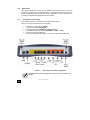
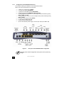
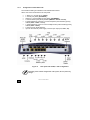
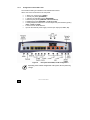
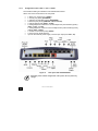
ONE100
Installation Manual
September 2008
http://www.oneaccess-net.com
OneAccess
28 rue de la Redoute
92260 Fontenay aux Roses
France
The law of 11 March 1957, paragraphs 2 and 3 of article 41, only authorizes, firstly,
’copies and reproductions strictly reserved for use by copyists and not for general
use and, secondly, analyses and short quotations for the purpose of example and
illustration. Therefore, ’any representation or reproduction, entire or partial, made
without the consent of the author or his representatives is illegal’ (paragraph 1 of
article 40).
Any such representation or reproduction, made in any manner whatsoever, would
therefore constitute an infringement of the law as sanctioned by articles 425 and in
accordance with the penal code.
Information contained in this document is subject to change without prior notice and
does not constitute any form of obligation on the part of OneAccess.
OneAccess and the distributors can in no case be held responsible for direct or
indirect damage of any kind incurred as a result of any error in the software or
guide.
Every care has been taken to ensure the exactitude of information in this manual. If
however you discover an error, please contact OneAccess After Sales Service
division.
July 2007 Issue
1100 00 T 4023102 T 00 ind. A
2
ONE100 - Installation Manual
How to Read this Manual
The present document is broken down into 7 chapters.
Chapter 1 – Safety Instructions
This chapter provides the safety instructions for use and installation of the router.
Chapter 2 – Directives and Standards
This chapter details the list of standards, which the device complies with.
Chapter 3 – Router Description
This section describes the router front and rear panels and the associated technical
characteristics.
Chapter 4 – Interface Description
This section describes the router interfaces.
Chapter 5 – Technical Characteristics
This section describes technical characteristics such as operating conditions.
Chapter 6 - Installation
This chapter describes how to modify the jumper positions and gives instructions to
connect the router.
Chapter 7 – Power-up
This chapter describes the device power-up and how to monitor the self-test
progress.
Appendix – Connection description
These chapters provide the pin-out of cables that are compatible with the router.
3
ONE100 - Installation Manual
Table of Contents
How to Read this Manual ........................................................................................................................3
Table of Contents ....................................................................................................................................4
1
Safety Instructions ........................................................................................................................5
1.1
1.2
1.3
1.4
2
Directives and Standards..............................................................................................................9
2.1
2.2
2.3
3
Declaration of Conformity........................................................................................................9
Standards ..............................................................................................................................10
FCC Statement (USA) ...........................................................................................................11
Router Description ......................................................................................................................12
3.1
3.2
3.3
3.4
3.5
4
Hardware Description............................................................................................................12
Front Panel ............................................................................................................................13
Rear Panel ............................................................................................................................15
Motherboard ..........................................................................................................................21
Configuration Identification....................................................................................................22
Interface Description...................................................................................................................23
4.1
4.2
4.3
4.4
4.5
4.6
4.7
4.8
4.9
5
LAN 10/100 Mbps Interface (ETHERNET)............................................................................23
Console port (CONSOLE) .....................................................................................................24
ADSL - ADSL 2/2 + - RE-ADSL Interface (ADSL).................................................................25
Ethernet Switch Interface (SWITCH).....................................................................................26
PSTN Modem Interface (PSTN) ............................................................................................27
RS 232 Interface (V.28).........................................................................................................28
FXS Analog Interface ............................................................................................................30
FXO Analog Interface............................................................................................................31
S0/T0 interface ......................................................................................................................32
Technical Characteristics............................................................................................................36
5.1
5.2
5.3
6
Climatic Environment ............................................................................................................36
Power Supply ........................................................................................................................36
Dimensions............................................................................................................................36
Installation...................................................................................................................................37
6.1
6.2
6.3
6.4
7
Connection to Power Supply ...................................................................................................5
Overcurrent Protection ............................................................................................................5
WiFi .........................................................................................................................................6
Safety Level Interface..............................................................................................................7
Opening the Chassis .............................................................................................................37
Install the WLAN antenna......................................................................................................37
Wall Mounting........................................................................................................................38
Connections ..........................................................................................................................39
Power up.....................................................................................................................................40
Appendix A - Console Cable .................................................................................................................41
Appendix B - RS 232 Interface Cable....................................................................................................42
4
ONE100 - Installation Manual
1
Safety Instructions
The following symbol instructs the user to read the manual carefully before any
connection:
1.1
Connection to Power Supply
To connect the power supply, always follow these steps:
•
•
Connect the DC input jack from the power supply to the DC 12V power input
on the rear panel of the router,
Connect the power supply to an AC electrical outlet (200-240 VAC). Plugging
in the power supply turns on the router.
Unplug the AC input before assembling/disassembling any part on the
device. The AC input is the part you must disconnect first. For safety reasons, you shall be able to easily access this part.
1.2
Overcurrent Protection
The product requires that the building’s electrical installation is designed for
protection against short-circuit (over current) protection.
A fuse or circuit breaker no larger than 240 VAC, 10A must be used on the phase
conductors.
5
ONE100 - Installation Manual
1.3
WiFi
1.3.1
National restrictions
Country
Restriction
Bulgaria
Outdoor use limited to 10 mW e.i.r.p.
within the band 2454-2483.5 MHz
France
Italy
Luxembourg
None
Implemented
Norway
Russian Federation
1.3.2
Reason/Remark
General authorization required for
outdoor use and public service.
Military Radiolocation use. Refarming of
the 2,4 GHz band has been ongoing in
recent years to allow current relaxed
regulation. Full implementation planned
2012.
If used outside of own premises, general
authorization is required.
General authorization required for
network and service supply (not for
spectrum)
This subsection does not apply for the
geographical area within a radius of
20km from the centre of Ny-Alesund
Only for indoor applications
Geographical restrictions
For sefaty reason the userhas to keep his distance to 20 cm from the
antenna.
1.3.3
Physical restrictions
The user cannot modify any part of the equipment and the antenna.
6
ONE100 - Installation Manual
1.4
Safety Level Interface
The daughter board must be installed only in the products authorized by
OneAccess and only by qualified personnel as recommended in the
installation manual.
1.4.1
LAN Interface 10/100 Mbps (ETHERNET and/or SWITCH)
Interface marking on the router back panel: ETHERNET and SWITCH
The Ethernet 10/100 Mbps auto-sense has a ’SELV’ (Safety Extra Low Voltage)
interface.
They must be used only for indoor applications, connected to a 10/100 Mbps
interface, which has also the ’SELV’ characteristics.
1.4.2
ADSL, ADSL 2/2+, RE-ADSL (ADSL)
Interface marking on the router back panel: ADSL
The router has an ADSL interface TNV-3 type (Telephone Network Voltage),
designed for connection to a telephone line.
1.4.3
PSTN Modem Interface (PSTN)
Interface marking on the router back panel: PSTN
The analog MODEM interface V.32 (bis)/V.34/V.90/V.92 is ’TNV-3’. It must be
connected to a standard telephone line.
1.4.4
RS 232 Interface (V.28)
Interface marking on the router back panel: V.28
The interface is SELV. It must be used only for indoor applications and connected to
RS 232 interfaces, which are also designed as ’SELV’.
1.4.5
FXS Interface (FXS)
Interface marking on the router back panel: FXS
The FXS modules offer up to 8 FXS accesses (RJ45 connectors). These Interfaces
are ’TNV 2’ (Telephone Network Voltage).
1.4.6
FXO Interface (FXO)
Interface marking on the router back panel: FXO
7
ONE100 - Installation Manual
The FXO interface is TNV-3.
1.4.7
T0/S0 interface (ISDN BRI)
Interface marking on the router back panel: ISDN BRI
These BRI interfaces are TNV-1. The TE mode is not available for Malaysia.
The factory configuration of these interfaces is T0, NT mode. Do not
connect the interfaces to a public ISDN access, which can damage the
product immediately.
8
ONE100 - Installation Manual
2
Directives and Standards
2.1
Declaration of Conformity
9
ONE100 - Installation Manual
2.2
Standards
The ONE100 is designed in conformity with the standards listed hereafter, provided
that the basic housing, modules, interface boards and installation kits are mounted
as recommended in the corresponding installation manual(s).
Safety
EN60950-1: 2001, First
Edition
Safety of information technology equipment, including electrical
business equipment.
Environment:
Climatic, physico chemical, mechanic, packing
ETS 300 019-1 (95)
Environmental conditions and environmental testing for
telecommunication equipment
In use: Temperature Controlled
Test specification:
Part 1, Classification of environmental conditions
- class T3.1 (normal)
- class T3.1 (exceptional)
Storage: partly temperature controlled
T1.1
Part 2, Specification of environmental test
Transportation: careful Transportation
T2.3
Electromagnetic Compatibility, immunity
ETSI EN 301 489-17 V1.2.1 ElectroMagnetic Compatibility (EMC) standard for radio equipment
and services.
(2002-08)
Part 17: Specific conditions for 2,4 GHz wideband transmission
systems and 5 GHz high performance RLAN equipment.
ETSI EN 300 328 V1.7.1
ETSI EN 300 386 V.1.3.3
(2005-04)
Data transmission equipment operating in the 2,4 GHz ISM band
and using wide band modulation techniques;
Harmonized EN covering essential requirements under article 3.2
of the R&TTE Directive.
Telecommunication network equipment;
ElectroMagnetic Compatibility (EMC) requirements.
Waste Electrical and Electronic Equipment
2002/96/EC
The ONE100 respects the European directive on the waste
disposal from the electrical and electronics components.
Restricted use of Hazardous Substances (RoHS)
2002/95/EC
10
The ONE100 respects the European directive on the restricted use
of Hazardous Substances in electric and electronic equipment.
ONE100 - Installation Manual
2.3
FCC Statement (USA)
The United States Federal Communications Commission (in 47 CFR 15.105) has
specified that the following notice be brought to the attention of users of this product:
This device has been tested and found to comply with the limits for a Class B digital
device, pursuant to part 15 of the FCC Rules. These limits are designed to provide
reasonable protection against harmful interference in a residential installation. This
device generates, uses and can radiate radio frequency energy and, if not installed
and used in accordance with the instructions, may cause harmful interference to
radio communications. However, there is no guarantee that interference will not
occur in a particular installation. If this device does cause harmful interference to
radio or television reception, which can be determined by turning the device off and
on, the user is encouraged to try to correct the interference's by one or more of the
following measures:
•
Reorient or relocate the receiving antenna.
•
Increase the separation between the device and the receiver.
•
Connect the device into an outlet on a circuit different from that to which the
receiver is connected.
•
Consult the dealer or an experienced radio/TV technician for help.
The user may find the following booklet, prepared by the Federal Communications
Commission, helpful: How to Identify and Resolve Radio/TV Interference Problems.
This booklet is available from the U.S. Government Printing Office, Washington,
D.C. 20402, Stock No. 004-000-00345-4.
Use of a shielded cable is required to comply within Class B limits of Part 15 of FCC
Rules.
Pursuant to Part 15.21 of the FCC Rules, any changes or modifications to this
device not expressly approved by OneAccess may cause, harmful interference and
void the FCC authorization to operate this device.
11
ONE100 - Installation Manual
3
Router Description
3.1
Hardware Description
3.1.1
Motherboard Interfaces
The ONE100 motherboard is equipped with the following interfaces. The interface
marking is indicated in bold and between brackets.
•
•
•
•
•
•
1 ADSL, ADSL 2/2+, RE-ADSL access (ADSL),
1 console port (CONSOLE),
1 managed switch with 4 ports (SWITCH),
0 to 4 ISDN S0/T0 access, which can be configured in TE or NT mode (ISDN
BRI),
2 optional interface WLAN 802.11b/g,
1 additional Ethernet port (LAN 100 BT) can be optionally built-in
(ETHERNET).
The addional Ethernet interface of the ONE100 only supports the 100 Mbps
full-duplex operations in auto-sense mode. If connected to devices in 10
mbps or half-duplex, the ONE100 interface will not be connected. The
problem can appear mostly with devices forced in such mode or with old
Ethernet hub.
3.1.2
Daughter-Board
A daughter-board provides additional ports on the ONE100. Please note that the
ONE100 can treat up to 8 simultaneous channels voice. The following ports are
provided on the various types of daughter-boards and their markings on router backpanel are indicated in bold between brackets:
•
•
•
•
•
0 to 4 ISDN access S0 in TE (for connection to ISDN public network only)
(ISDN BRI),
0 to 8 analog access designed to connect telephone (FXS interface) (FXS),
0 to 1 analog access designed to connect telephone line (FXO interface)
(FXO),
0 to 1 modem access PSTN (PSTN),
0 or 2 V.28 interface.
The addition of a daughter-board enables the installation of one of the following
interfaces:
•
•
•
•
•
•
12
2 FXS,
4 FXS,
4 FXS, 1 FXO,
8 FXS,
8 FXS, 1 FXO,
4 FXS, 1 FXO, 1 PSTN modem, 2 V.28 interface,
ONE100 - Installation Manual
•
2/4 BRI S0 only in TE.
The ONE100 is delivered as a product bundle consisting of a motherboard
pre-equipped with its daughter-board. Only a limited number of
motherboard/daughter-board combinations is commercialised. For more
details, please contact your sales representatives.
3.2
Front Panel
The front panel is provided with LEDS, which inform about the status of several
router functions.
Figure 1.
13
ONE100 - Installation Manual
Front panel
Leds
OFF
Green
Red
Orange
Blinking green
Status
Switched Off
Switched On &
Operational
Switched On &
Not operational
Reboot in
progress
Uplink
Not used
DSL Synchronized
Loss of
synchronization
Synchronization
in progress
IP
Not used
All IP interfaces are
up
All IP interfaces
are down
WLAN
Not used
Interface up
Aux
Com
14
Configured and
operational voice
service
No voice
communication
At least one
IP Interface is
not up
(example:
PPPoA not
connected)
Traffic in
progress
Malfunction in
voice service
Voice Compression
operational on one
or several channels
ONE100 - Installation Manual
Voice service
configured,
verification of
voice function in
progress.
3.3
Rear Panel
This section details the various types of ONE100 rear panel so that the user can
identify the interface type and port numbering. It should be noted that only the fullyloaded configurations are represented. Other configurations can be derived by not
providing some interfaces represented on the product.
3.3.1
Configuration with 4 ISDN
The interface marking is indicated in bold and between bracket.
All the connectors are located on the rear panel:
•
•
•
•
•
•
1 ADSL 2/2 + access (RJ11) (ADSL)
1 console port (RJ45) (CONSOLE),
4 Ethernet ports (RJ45) (SWITCH – E0-0/0 - E3-0/3),
0 to 4 ISDN access S0/T0 (RJ45) (ISDN BRI – L0-5/0 - L3-5/3),
2 connectors for WLAN antenna,
Input for the external power supply connector (DC input jack, 12V-1, 7A).
Figure 2.
Rear panel with 4 BRI configuration
Depending of the ordered configuration of the system, the rear panel may
change.
15
ONE100 - Installation Manual
3.3.2
Configuration with FXS/FXO/PSTN board
The interface marking is indicated in bold and between bracket.
All the connectors are located on the rear panel:
•
•
•
•
•
•
•
•
•
•
1 ADSL 2/2+ access (RJ11) (ADSL),
1 console port (RJ45) (CONSOLE),
1 optional LAN 100 Mbps (RJ45) (ETHERNET),
4 Ethernet ports (RJ45) (SWITCH – E0-0/0 - E3-0/3),
4 analog telephone interfaces to connect telephones (FXS interface) (RJ45),
(FXS – L0-5/0 – L3-5/3),
1 analog telephone access to connect telephone line (FXO interface) (RJ45),
(FXO – L4-5/4),
1 modem access PSTN (RJ45) (PSTN),
2 V.28 interface (V.28 – S0 - S1),
2 connectors for WLAN antenna,
Input for the external power supply connector (DC input jack, 12V-1, 7A).
Figure 3.
Rear panel with FXS/FXO/PSTN configuration
Depending of the ordered configuration of the system, the rear panel may
change.
16
ONE100 - Installation Manual
3.3.3
Configuration with 8 FXS/1 FXO
The interface marking is indicated in bold and between bracket.
All the connectors are located on the rear panel:
•
•
•
•
•
•
•
•
1 ADSL 2/2 + access (RJ11) (ADSL),
1 console port (RJ45) (CONSOLE),
Optional, 1 LAN 100 Mbps access (RJ45) (ETHERNET),
4 communication ports (RJ45) marked (SWITCH – E0-0/0 - E3-0/3),
8 analog telephone accesses to connect telephone (FXS interface) (RJ45),
marked (FXS – L0-5/0 – L7-5/7),
1 analog telephone access to connect telephone line (FXO interface) (RJ45),
marked (FXO – L8-5/8),
2 connectors for WLAN antenna,
Input for the external power supply connector (DC input jack, 12V-1, 7A).
Figure 4.
Rear panel with 8 FXS, 1 FXO configuration
Depending of the ordered configuration of the system, the rear panel may
change.
17
ONE100 - Installation Manual
3.3.4
Configuration with 4 BRI/ 2 FXS
The interface marking is indicated in bold and between bracket.
All the connectors are located on the rear panel:
•
•
•
•
•
•
•
•
1 ADSL 2/2+ access (RJ11) (ADSL),
1 console port (RJ45) (CONSOLE),
1 optional LAN 100 Mbps (RJ45) (ETHERNET),
4 Ethernet ports (RJ45) (SWITCH – E0-0/0 to E3-0/3),
4 ISDN S0/T0 (RJ45) (ISDN BRI – L0-5/0 to L3-5/3),
2 analog telephone interfaces to connect telephones (FXS interface) (RJ45),
(FXS – L4-5/4 to L5-5/5),
2 connectors for WLAN antenna,
Input for the external power supply connector (DC input jack, 12V-1, 7A).
Figure 5.
Rear panel with 4 BRI, 2 FXS configuration
Depending of the ordered configuration of the system, the rear panel may
change.
18
ONE100 - Installation Manual
3.3.5
Configuration with 1 FXS + 1 FXO + 1 ISDN
The interface marking is indicated in bold and between bracket.
All the connectors are located on the rear panel:
•
•
•
•
•
•
•
•
•
1 ADSL 2/2+ access (RJ11) (ADSL),
1 console port (RJ45) (CONSOLE),
1 optional LAN 100 Mbps (RJ45) (ETHERNET),
4 Ethernet ports (RJ45) (SWITCH – E0-0/0 - E3-0/3),
1 backup ISDN access (ISDN – L0-5/0),
4 analog telephone interfaces to connect telephones (FXS interface) (RJ45),
(FXS – L1-5/1 – L4-5/4),
1 analog telephone access to connect telephone line (FXO interface) (RJ45),
marked (FXO – L5-5/5),
1 modem access PSTN (RJ45) (PSTN),
2 connectors for WLAN antenna,
Input for the external power supply connector (DC input jack, 12V-1, 7A).
Figure 6.
Rear panel with FXS/FXO/ISDN
Depending of the ordered configuration of the system, the rear panel may
change.
19
ONE100 - Installation Manual
3.3.6
Configuration with 4 + 4 BRI
The interface marking is indicated in bold and between bracket.
All the connectors are located on the rear panel:
•
•
•
•
•
•
1 ADSL 2/2+ access (RJ11) (ADSL),
1 console port (RJ45) (CONSOLE),
4 Ethernet ports (RJ45) (SWITCH – E0-0/0 - E3-0/3),
4 ISDN S0/T0 (RJ45) (ISDN BRI – L0-5/0 - L3-5/3),
4 ISDN S0/T0 (RJ45) (ISDN BRI – L4-5/4 – L7-5/7),
2 connectors for WLAN antenna,
Input for the external power supply connector (DC input jack, 12V-1, 7A).
Figure 7.
Rear panel with 4 + 4 BRI
Depending of the ordered configuration of the system, the rear panel may
change.
20
ONE100 - Installation Manual
3.4
Motherboard
The motherboard provides:
•
•
•
•
•
Router resources (CPU, DSP, memory RAM and Flash),
Standard router interfaces (console interface, Fast Ethernet, and LEDs),
Optional connector for WLAN interface,
The connector intended to receive motherboards,
Jumpers enabling features configuration of interfaces BRI and motherboard.
Figure 8.
Motherboard
Depending on the ordered configuration of the system, the composition of
the device may change.
21
ONE100 - Installation Manual
3.5
Configuration Identification
The different device configurations are identified by adding one or several letters to
the device naming and printed on the router labeling sticker.
Options codification:
•
•
•
•
•
B: ISDN BRI access,
E: Switch Ethernet function,
A: ADSL, ADSL 2/2 + access, 2 possible versions,
•
ADSL annex A,
•
ADSL annex B and B-DT,
V: FXS interface,
W: WLAN interface.
Example:
ONE100 4B-2V AEW/a is a ONE100 router equipped with:
•
•
•
•
•
22
4 ISDN BRI accesses,
2 FXS, interfaces,
1 ADSL access Annex A,
Ethernet Switch function,
2 WLAN interface.
ONE100 - Installation Manual
4
Interface Description
4.1
LAN 100 Mbps Interface (ETHERNET)
4.1.1
Characteristics
•
•
•
•
100Base-TX,
Full duplex,
Auto-negotiation.
Auto MDI/MDX
The Ethernet interface of the ONE100 only supports the 100 Mbps fullduplex operations in auto-sense mode. If connected to devices in 10 mbps
or half-duplex, the ONE100 interface will not be connected. The problem can
appear mostly with devices forced in such mode or with old Ethernet hub.
4.1.2
Meaning of LED Colors
Lit green Led
Blinking yellow Led
4.1.3
Link active
Traffic in progress
Connector Pinout
RJ45 Connector:
Pin
4.1.4
Signal
Pin
1
TD (+)
5
NC
2
TD (-)
6
RD (-)
3
RD (+)
7
NC
4
NC
8
NC
Cables
A standard Ethernet cable is needed (shielded UTP Cat. 5).
23
ONE100 - Installation Manual
Signal
4.2
4.2.1
Console port (CONSOLE)
Characteristics
•
•
•
4.2.2
RS 232,
9600 bps,
8 bits, 1 bit for stop, no parity.
Connector Pinout
RJ45 Connector:
Pin
-
Signal
Pin
Signal
1
TX
5
NC
2
RX
6
Cable type
3
GND
7
CTS
4
NC
8
RTS
TX: Transmission
RX: Reception
NC: Not connected
GND: Ground
CTS: Clear-To-Send
RTS: Ready-To-Send
A console cable for router configuration and maintenance only requires TX, RX and
GND to be connected.
If the pin 6 is connected to the ground (pin 3), the cable is then identified as a cable
connected to an asynchronous terminal. In that case, CTS and RTS can be used.
4.2.3
Cables
The console cable is defined in Appendix A.
24
ONE100 - Installation Manual
4.3
4.3.1
ADSL - ADSL 2/2 + - RE-ADSL Interface (ADSL)
Characteristics
•
•
•
4.3.2
ADSL: G.DMT Annex A (ADSL over POTS), G.DMT Annex B (ADSL over
RNIS, U-R2 compliant),
ADSL2, (G.992.3) / ADSL 2+ (G.992.5) / RE-ADSL (Reach Extended ADSL,
G.992.3 Annex L),
Dying gasp
Connector Pinout
RJ11 Connector:
Pin
4.3.3
Signal
1
NC
2
TIP
3
RING
4
NC
Cables
The cable of connection to the ADSL must be made using a standard phone cable.
25
ONE100 - Installation Manual
4.4
4.4.1
Ethernet Switch Interface (SWITCH)
Characteristics
The switch Ethernet function offers 4 ports Ethernet. Every port can be switched
and/or routed.
•
•
•
•
4.4.2
10/100 Mbits/s,
Half or full duplex,
Auto-negotiation,
Auto MDI/MDIX.
Meaning of LED Colors
Green LED Lit
Blinking yellow LED
4.4.3
Link active
Traffic in progress
Connector Pinout
RJ45 Connector:
Pin
4.4.4
Signal
Pin
Signal
1
TD (+)
5
NC
2
TD (-)
6
RD (-)
3
RD (+)
7
NC
4
NC
8
NC
Cables
The cables are shielded, crossover/straight cables with 4 twisted pairs. The switch
supports autodetection of crossover/straight cable (’auto-MDI/MDI-X detection’); the
transmission pairs are (1-2) and receive pairs are (3-6).
26
ONE100 - Installation Manual
4.5
4.5.1
PSTN Modem Interface (PSTN)
Characteristics
The router can be equipped with a daughter board delivering an access to the PSTN
via an integrated analog modem.
•
•
4.5.2
Compatible with V.32, V.32bis, V.34, V.90 and V.92,
Compliant with TBR21.
Connector Pinout
RJ45 Connector:
Pin
4.5.3
Signal
Pin
1
NC
5
TIP
2
NC
6
NC
3
NC
7
NC
4
RING
8
NC
Cables
The cable is a standard telephone cord with one twisted pair.
27
Signal
ONE100 - Installation Manual
4.6
4.6.1
RS 232 Interface (V.28)
Characteristics
An extension board provides 2 RS 232 access.
The ports are the following characteristics:
•
•
•
•
4.6.2
Synchronous mode, contra-directional, single clock, DCE or DTE mode is
supported (configuration with jumpers),
Asynchronous mode (< 115 kbits/s),
Electrical Interface V.28,
Signals managed (8): 102, 103, 104, 105 (RTS), 106, 108 (RTS), 109 (CD),
115.
Connector Pinout
RJ45 Connector:
Pin
4.6.3
Signal
Pin
Signal
1
115 / RXC
5
103 / SD
2
105 / DPE
6
108 / ETDP
3
104 / RD
7
102 / GND
4
109 / DS
8
106 / PAE
RS 232 Configuration
Each RS 232 interface can be separately configured in DTE or DCE mode when
using the synchronous mode:
PORT 0
PORT 1
X2
DCE
1
X1
1
DCE_DTE
DCE_DTE
X1
X2
DTE
1
1
DCE_DTE
DCE_DTE
When using the asynchronous mode, the jumper connection is not relevant.
28
ONE100 - Installation Manual
4.6.4
Cables
The cable type must correspond to the desired more (DCE or DTE). All types of
cord for RS 232 port are defined in Appendix B.
29
ONE100 - Installation Manual
4.7
FXS Analog Interface
The FXS interface enables the connection of up to 4 or up to 8 analog telephone
lines thus providing up to 8 analog voice interfaces.
The connection of the FXS interfaces is done via RJ45 connectors (1 connector per
FXS).
4.7.1
Characteristics
•
•
•
•
•
•
•
•
4.7.2
Line impedance: 600 Ω or complex,
Frequency range of the ringing signal: 16Hz to 70 Hz,
Voltage of the ringing signal: > 37,4VRMS for a load of 1 REN (6,93K + 8µF
@ 20Hz) in the frequency range,
Line current: 27 mA max. for a line resistance <1000 Ω,
Polarity inversion of the TIP and RING pins,
Line current <2mA in the power-down mode,
Q.23 dialing.
Ringer Equivalency Number (REN): 1
Connector Pinout
The connection to the analog voice interface is made on the rear panel via an RJ45
connector. The connector pinout is as follows:
Pin
4.7.3
Signal
Pin
Signal
1
NC
5
TIP
2
NC
6
NC
3
NC
7
NC
4
RING
8
NC
Cables
The cable used for a connection toward a analog phone is an unshielded cable
including 1 twisted pair.
The ONE100 with FXS interfaces has got a screw marked located on the
rear panel. This must be permanently connected to the main protective
earth.
30
ONE100 - Installation Manual
4.8
FXO Analog Interface
The FXO module enables the connection of 1 analog telephone line.
The connection of the FXO interfaces is done via RJ45 connectors (1 connector per
FXO).
4.8.1
Connector Pinout
RJ45 Connector:
Pin
4.8.2
Signal
Pin
Signal
1
NC
5
TIP
2
NC
6
NC
3
NC
7
NC
4
RING
8
NC
Cables
The cable used for a connection toward a standard analog phone is an unshielded
cable including 1 twisted pair.
31
ONE100 - Installation Manual
4.9
S0/T0 interface
The ONE100 supports up to 4 ISDN interface S0/T0. The interfaces can be
configured in TE or NT.
The connection of the digital voice interface is carried out on the rear panel via RJ45
connectors (1 connector by interface).
The factory configuration of these interfaces is T0 mode. Do not connect the
interfaces with a public ISDN access without ensuring that jumper positions
are correct. The product can be damaged definitively otherwise.
You can connect/disconnect the power-supply of all ISDN ports by using the
command ‘CLI(voice-port)# [no] power-source-one’ without changing the
default jumper factory settings.
To respect the environmental norm, cables connected to the interfaces
T0/S0 (ISDN/BRI) must be shielded.
4.9.1
Mother board configuration
Every ISDN interface has four jumpers making it possible to configure the following
options:
•
100 Ohms impedance adaptation,
•
Power-feeding for ISDN phones
The drawing below presents the position of the 4 blocks of 4 jumpers on the mother
board:
Figure 9.
32
Positioning of the 4 blocks of jumpers
ONE100 - Installation Manual
The WATCHDOG jumper must always be connected so that OneAccess guarantees
the correct operation of the ONE100.
Description of a block of jumpers for a BRI interface.
100 Ohms Adaptation
Receiving Pair
100 Ohms Adaptation
Sending Pair
Power supply 30VN
Power supply 30 VP
Not used
Each block of jumpers allows:
•
•
To connect or not a 100 Ohms impedance adaptation,
To connect the power supply for ISDN terminal (30 volts).
For the power feeding, jumpers operating in pairs:
•
•
No power feeding, both jumpers removed,
With power feeding, both jumpers set.
For 100 Ohms adaptation, jumpers can be used in sending, in receiving or in
sending/receiving.
You find below some examples of configurations according to the position of the
jumpers:
33
ONE100 - Installation Manual
Configuration without impedance adaptation and power feeding of the terminal:
Configuration
100 Ohms impedance adaptation
disconnected.
Power feeding for ISDN terminal
disconnected.
Configuration with impedance adaptation and without power feeding of the terminal:
Configuration
100 Ohms impedance adaptation
connected. The first jumper of the pair is
associated with the transmission, the
second one with the reception.
Power feeding for ISDN terminal
disconnected.
Configuration without impedance adaptation and with power feeding of the terminal:
Configuration
100 Ohms impedance adaptation
disconnected.
Power feeding for ISDN terminal
connected.
Configuration with impedance adaptation and with power supply of the terminal:
Configuration
100 Ohms impedance adaptation
connected. The first jumper of the pair is
associated with the transmission, the
second one with the reception.
Power feeding for ISDN terminal
connected.
34
ONE100 - Installation Manual
4.9.2
Connector Pinout
4.9.2.1 Mother board connectors
The connection to the BRI accesses is made on the rear panel via RJ-45
connectors. The RJ45 connector pinout is:
Pin
Signal
Pin
Signal
1
NC
5
TX (-)
2
NC
6
RX (-)
3
RX (+)
7
NC
4
TX (+)
8
NC
4.9.2.2 Daughter board connectors
The connection to the BRI accesses is made on the rear panel via RJ-45
connectors. The RJ45 connector pinout is:
Pin
35
Signal
Pin
Signal
1
NC
5
RX (-)
2
NC
6
TX (-)
3
TX (+)
7
NC
4
RX (+)
8
NC
ONE100 - Installation Manual
5
Technical Characteristics
5.1
Climatic Environment
Operating Conditions:
Temperature
0° C ≤ T ≤ 45°C
Relative Humidity (HR)
5% ≤ HR ≤ 80%
Absolute Humidity
≤ 24g / m3
Altitude
≤ 2500 m
Storage Environment:
5.2
- 25° C ≤ T ≤ 55°C
Relative Humidity (HR)
5% ≤ HR ≤ 80%
Absolute Humidity
≤ 24g / m3
Altitude
≤ 2500 m
Power Supply
•
5.3
Temperature
External Power Supply 200-240 VAC / 20W (12V – 1.7A),
Dimensions
The dimensions of the housing are:
36
Width
275 mm
Height
68 mm
Depth
152 mm
ONE100 - Installation Manual
Installation
6
Always unplug the power AC cable before any hardware maintenance
operation.
This chapter describes assembling/disassembling operations for optional modules.
The user should be aware that the router software auto-detects on-board modules
and interfaces.
All vacant slots of the rear panel must be obstructed with suitable faceplates in order to guarantee the respect of the EMC standards as defined in
Chapter 2. Directives and Standard
6.1
Opening the Chassis
1
2
3
6.2
Unlock the rear panel screw and removing it.
Unclip the lower part of the front panel.
Remove the cover.
Install the WLAN antenna
Please raise it in a vertical position.
37
ONE100 - Installation Manual
6.3
Wall Mounting
The lower part of the router has 2 notches in order to enable wall-mounting. By
installing two screws at the required distance, the router can be hung on any vertical
surface.
Instructions:
1.
2.
3.
Bore two horizontal holes separated by 244 mm of distance if the router is
hung with the rear panel in the upper position
Mount both screws in each hole. Do not screw them completely but leave a
distance of 5 mm between the wall and the head of the screw,
Hang the router gently and if necessary adjust the screws in the notches of
the router.
Figure 10.
38
Positioning of the notches
1
Rear panel of the router
3
Notches
2
Bottom of the router
4
Distance between holes: 244 mm
ONE100 - Installation Manual
6.4
Connections
The external power supply is connected on the rear panel of the device.
The external power supply is delivered with the router package.
•
•
Connect the ’jack’ connector of the external power supply to the connector
marked ’12V-1.7A’ device connector,
Secure the power supply connection by installing the DC power supply cord
into the plastic ring.
The device shall not be used with another power supply than a power
supply recommended by OneAccess.
39
ONE100 - Installation Manual
7
Power up
To power up the device, always follow these steps:
•
Connect the DC power input jack from the power supply to the DC power
input of the rear panel of the router,
•
Connect the power supply to the AC mains (200-240 V AC).
Few seconds after power-on, the device performs a series of self-tests and loads
the software into memory (RAM), during which the ’STATUS’ LED on the front panel
blinks.
At the end of software loading (about 30 seconds):
•
•
The ’STATUS’ LED light remains steady green if software initialization was
successful,
The ’STATUS’ LED blinks in case of software absence or error during
software loading.
Refer to the Software and ONEOS User Guide for more information.
40
ONE100 - Installation Manual
Appendix A - Console Cable
Catalog reference: 4 022 332 B 00 Ed A
P1
41
To PC
serial port
in terminal
mode
(Configuration)
P2
RJ45 - P1
SIGNAL
SUB-D 9 Pts
Female - P2
1
2
3
TX
RX
GND
2
3
5
ONE100 - Installation Manual
Appendix B - RS 232 Interface Cable
B.1 V.28 / RS 232 DTE
Catalog reference: 4022 815 B 00
P1
P2
- P1 RJ45
SIGNAL
P2 SUB-D 25 Pts
Male
1
2
115 (RXC)
106 (CTS)
17
5
3
103 (SD)
2
4
108 (DTR)
20
5
104 (RD)
3
6
109 (CD)
8
7
8
102
105 (RTS)
7
4
Screening
42
Shield
ONE100 - Installation Manual
B-2. V.28 / RS 232 DCE Cable
Catalog reference: 9594 508 07146
P1
43
P2
- P1 RJ45
SIGNAL
P2 SUB-D 25 Pts
female
1
115 (RXC)
17
2
3
105 (RTS)
104 (RD)
4
3
4
109 (CD)
8
5
103 (SD)
2
6
108 (DTR)
20
7
102
7
8
Screening
106 (CTS)
5
Shield
ONE100 - Installation Manual