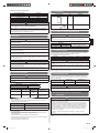
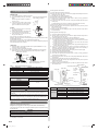
1
AIR CONDITIONER
OUTDOOR UNIT
MANUAL DE INSTALACIÓN
Solo para personal autorizado.
MANUALE D'INSTALLAZIONE
Ad uso esclusivo del personale autorizzato.
ΕΓΧΕΙΡΙΔΙΟ ΕΓΚΑΤΑΣΤΑΣΗΣ
Για εξουσιοδοτημένο προσωπικό σέρβις.
MANUAL DE INSTALAÇÃO
Apenas para técnicos autorizados.
РУКОВОДСТВО ПО УСТАНОВКЕ
Для уполномоченного персонала.
KURULUM KILAVUZU
Yetkili servis personeli içindir.
Deutsch
Français
Español
Pour le personnel agréé uniquement.
Italiano
MANUEL D'INSTALLATION
EλληvIkά
Nur für autorisiertes Personal.
Português
INSTALLATIONSANLEITUNG
Русский
For authorized service personnel only.
Türkçe
INSTALLATION MANUAL
English
INSTALLATION MANUAL
PART No. 9377863195
9377863195_IM.indb 1
1/18/2013 9:16:52 AM
AIR CONDITIONER
OUTDOOR UNIT
CAUTION
Read carefully all security information before use or install the air conditioner.
Do not attempt to install the air conditioner or a part of the air conditioner by yourself.
INSTALLATION MANUAL
9377863195
This unit must be installed by qualified personnel with a capacity certificate for handling
refrigerant fluids. Refer to regulation and laws in use on installation place.
The installation must be carried out in compliance with regulations in force in the place
of installation and the installation instructions of the manufacturer.
Contents
This unit is part of a set constituting an air conditioner. It must not be installed alone or
with non-authorized by the manufacturer.
1.
SAFETY PRECAUTIONS .......................................................................................... 1
2.
ABOUT THE UNIT ..................................................................................................... 1
The unit must be correctly earthed (grounded) and the supply line must be equipped
with a differential breaker in order to protect the persons.
3.
SELECTING THE MOUNTING POSITION ............................................................... 3
The units are not explosion proof and therefore should not be installed in explosive atmosphere.
4.
INSTALLATION DIAGRAM ........................................................................................ 3
5.
INSTALLATION ......................................................................................................... 4
This unit contains no user-serviceable parts. Always consult authorized service
personnel to repairs.
6.
PUMP DOWN ............................................................................................................ 6
Notes:
• This manual describes how to install the outdoor unit only. To install the indoor unit,
refer to the installation manual included with the indoor unit.
• Be sure to read this manual thoroughly before the installation.
• Hand this manual, together with the operating manual, to the customer. Request the
customer to keep them on hand for future use, such as for relocating or repairing the unit.
• After the installation, explain correct operation to the customer by using the operating manual.
1. SAFETY PRECAUTIONS
• Be sure to read this manual carefully before installation.
• The warnings and precautions indicated in this manual contain important information
pertaining to your safety. Be sure to observe them.
• Hand this manual, together with the operating manual, to the customer. Request the
customer to keep them on hand for future use, such as for relocating or repairing the
unit.
WARNING
This mark indicates procedures which, if improperly performed,
might lead to the death or serious injury of the user.
CAUTION
This mark indicates procedures which, if improperly performed,
might possibly result in personal harm to the user, or damage to
property.
WARNING
Never touch electrical components immediately after the power supply has been turned
off. Electrical shock may occur. After turning off the power, always wait 10 minutes or
more before touching electrical components.
Request your dealer or a professional installer to install the outdoor unit in accordance
with this installation manual. an improperly installed unit can cause serious accidents
such as water leakage, electric shock, or fire.
If the outdoor unit is installed in disregard of the instructions in the installation manual, it
will void the manufacturer’s warranty.
Do not turn ON the power until all work has been completed. Turning ON the power
before the work is completed can cause serious accidents such as electric shock or fire.
If refrigerant leaks while work is being carried out, ventilate the area. If the refrigerant
comes in contact with a flame, it produces a toxic gas.
Installation work must be performed in accordance with national wiring standards by
authorized personnel only.
When moving, consult authorized service personnel for disconnection and installation of
the unit.
Children should be monitored to ensure they do not play with the device.
This appliance is not intended for use by persons (including children) with reduced
physical, sensory or mental capabilities, or lack of experience and knowledge, unless
they have been given supervision or instruction concerning use of the appliance by a
person responsible for their safety. Children should be supervised to ensure that they do
not play with the appliance.
Do not touch the aluminum fins of heat exchanger built-in the indoor or outdoor unit to
avoid personal injury when you install or maintain the unit.
Do not place any other electrical products or household belongings under indoor unit or
outdoor unit. Dripping condensation from the unit might get them wet, and may cause
damage or malfunction of your property.
2. ABOUT THE UNIT
2.1. Precautions for using R410A refrigerant
The basic installation work procedures are the same as conventional refrigerant (R22)
models.
However, pay careful attention to the following points:
Since the working pressure is 1.6 times higher than that of conventional refrigerant
(R22) models, some of the piping and installation and service tools are special. (See
the table below.)
Especially, when replacing a conventional refrigerant (R22) model with a new refrigerant
R410A model, always replace the conventional piping and flare nuts with the R410A piping
and flare nuts.
Models that use refrigerant R410A have a different charging port thread diameter to prevent erroneous charging with conventional refrigerant (R22) and for safety. Therefore,
check beforehand. [The charging port thread diameter for R410A is 1/2 inch.]
Be more careful that foreign matter (oil, water, etc.) does not enter the piping than with
refrigerant (R22) models. Also, when storing the piping ,securely seal the opening by
pinching, taping, etc.
When charging the refrigerant, take into account the slight change in the composition of
the gas and liquid phases. And always charge from the liquid phase where refrigerant
composition is stable.
2.2. Special tools for R410A
Do not use this equipment with air or any other unspecified refrigerant in the refrigerant lines.
Excess pressure can cause a rupture.
During installation, make sure that the refrigerant pipe is attached firmly before you
run the compressor. Do not operate the compressor under the condition of refrigerant
piping not attached properly with 2-way or 3-way valve open. This may cause abnormal
pressure in the refrigeration cycle that leads to rupture and even injury.
When installing and relocating the air conditioner, do not mix gases other than the
specified refrigerant (R410A) to enter the refrigerant cycle.
If air or other gas enters the refrigerant cycle, the pressure inside the cycle will rise to
an abnormally high value and cause rupture, injury, etc.
For the air conditioner to operate satisfactorily, install it as outlined in this installation manual.
Connect the indoor unit and outdoor unit with the air conditioner piping and cable
available standards parts.
This installation manual describes the correct connections using the installation set
available from our standard parts.
Also, do not use an extension cable.
Do not purge the air with refrigerants but use a vacuum pump to vacuum the installation.
There is not extra refrigerant in the outdoor unit for air purging.
Using the same vacuum pump for different refrigerants may damage the vacuum pump or the unit.
Use a clean gauge manifold, vacuum pump and charging hose for R410A exclusively.
During the pump-down operation, make sure that the compressor is turned off before
you remove the refrigerant piping.
Do not remove the connection pipe while the compressor is in operation with 2 way or 3
way valve open. This may cause abnormal pressure in the refrigeration cycle that leads
to rupture and even injury.
Tool name
Gauge manifold
Contents of change
Pressure is high and cannot be measured with a conventional (R22) gauge. To prevent erroneous mixing of other
refrigerants, the diameter of each port has been changed.
It is recommended the gauge with seals -0.1 to 5.3 MPa
(-1 to 53 bar) for high pressure.
-0.1 to 3.8 MPa (-1 to 38 bar) for low pressure.
Charge hose
To increase pressure resistance, the hose material and base
size were changed.
Vacuum pump
A conventional vacuum pump can be used by installing a
vacuum pump adapter.
Gas leakage detector
Special gas leakage detector for HFC refrigerant R410A.
Copper pipes
It is necessary to use seamless copper pipes and it is desirable that the amount of residual
oil is less than 40 mg/10 m. Do not use copper pipes having a collapsed, deformed or
discolored portion (especially on the interior surface). Otherwise, the expansion value or
capillary tube may become blocked with contaminants.
As an air conditioner using R410A incurs pressure higher than when using R22, it is necessary to choose adequate materials.
Thicknesses of copper pipes used with R410A are as shown in table below. Never use
copper pipes thinner than 0.8mm even when it is available on the market.
En-1
9377863195_IM.indb 1
1/18/2013 9:16:53 AM
Thicknesses of Annealed Copper Pipes
2.5. Accessories
Pipe outside diameter
Thickness
6.35 mm (1/4 in.)
9.52 mm (3/8 in.)
12.70 mm (1/2 in.)
15.88 mm (5/8 in.)
19.05 mm (3/4 in.)
0.80 mm
0.80 mm
0.80 mm
1.00 mm
1.20 mm
Name and Shape
Installation Manual
Q’ty
Application
This manual
1
WARNING
Do not use the existing (for R22) piping and flare nuts.
If the existing materials are used, the pressure inside the refrigerant cycle will rise and
cause failure, injury, etc. (Use the special R410A materials.)
When installing and relocating the air conditioner, do not mix gases other than
the specified refrigerant (R410A) to enter the refrigerant cycle.
If air or other gas enters the refrigerant cycle, the pressure inside the cycle will rise to
an abnormally high value and cause failure, injury, etc.
For outdoor unit drain piping work
Drain pipe
1
2.6. Limitation of refrigerant piping length
CAUTION
2.3. Power
The total maximum pipe lengths and height difference of this product are shown in the
table.
If the units are further apart than this, correct operation cannot be guaranteed.
WARNING
Always use a special branch circuit and install a special receptacle to supply power to
the room air conditioner.
Use a circuit breaker and receptacle matched to the capacity of the air conditioner.
Do not extend the power cable.
Perform wiring work in accordance with standards so that the air conditioner can be
operated safely and positively.
Install a leakage circuit breaker in accordance with the related laws and regulations
and electric company standards.
The circuit breaker is installed in the permanent wiring. Always use a circuit that can
trip all the poles of the wiring and has an isolation distance of at least 3 mm between
the contacts of each pole.
The power source capacity must be the sum of the air conditioner current and the current of other electrical appliances. When the current contracted capacity is insufficient,
change the contracted capacity.
When the voltage is low and the air conditioner is difficult to start, contact the power
company the voltage raised.
2.4. Electric requirement
Regulation of cables and breaker differs from each locality, refer in accordance with
local rules.
Voltage rating
1 ø 230 V (50 Hz)
Operating range
198-264 V
•
•
•
•
5m
20 m
2.7. Additional charge
Refrigerant suitable for a piping length of 15 m is charged in the outdoor unit at the factory.
When the piping is longer than 15 m, additional charging is necessary.
For the additional amount, see the table below.
Pipe length
Additional amount
15 m
None
20 m
100 g
25 m
200 g
30 m
300 g
When adding refrigerant, add the refrigerant from the charging port at the completion
of work.
The maximum length of the piping is 30 m. The maximum height difference of the piping
is 20 m, if the units are further apart than these, correct operation cannot be guaranteed.
Between 15 m and 30 m, when using a connection pipe other than that in the table, charge
additional refrigerant with 20 g/1 m as the criteria.
Capacity of indoor unit
Gas pipe size
(thickness) [mm]
Liquid pipe size
(thickness) [mm]
24
ø15.88 (1.0)
ø6.35 (0.8)
CAUTION
Cable
Cable size [mm2]*1
Type
Remarks
Power supply cable
4.0
Type 60245
IEC66
2cable + Earth
(Ground), 1ø230V
1.5
Type 60245
IEC57
3cable + Earth
(Ground), 1ø230V
Selected sample: Select the correct cable type and size according to the country or
region’s regulations.
Max. wire length: Set a length so that the voltage drop is less than 2%. Increase the
wire diameter when the wire length is long.
Breaker
Specification*2
Circuit breaker (over current)
Current : 25 (A)
Earth leakage breaker
Leakage current : 30mA 0.1sec or less*3
*3
30 m
The diameters of the connection pipes differ according to the capacity of the indoor unit.
Refer to the following table for the proper diameters of the connection pipes between the
indoor and outdoor units.
Be sure to install a breaker of the specified capacity.
*2
Maximum height
(between indoor and outdoor)
2.8. Selecting pipe sizes
CAUTION
*1
MIN.
CAUTION
CAUTION
Connection cable
Pipe length
MAX.
Select the appropriate breaker of the described specification according to the national
or regional standards.
Select the breaker that enough load current can pass through it.
Before starting work check that power is not being supplied to all poles of the indoor
unit and outdoor unit.
Install all electrical works in accordance to the national standard.
Install the disconnect device with a contact gap of at least 3 mm in all poles nearby the
units. (Both indoor unit and outdoor unit)
Install the circuit breaker nearby the units.
Operation cannot be guaranteed if the correct combination of pipes, valves, etc., is not
used to connect the indoor and outdoor units.
2.9. Heat insulation around connection pipes
requirements
CAUTION
Install heat insulation around both the gas and liquid pipes.
Failure to do so may cause water leaks.
Use heat insulation with heat resistance above 120 °C. (Reverse cycle model only)
In addition, if the humidity level at the installation location of the refrigerant piping is
expected to exceed 70%, install heat insulation around the refrigerant piping. If the
expected humidity level is 70-80%, use heat insulation that is 15 mm or thicker and if
the expected humidity exceeds 80%, use heat insulation that is 20 mm or thicker.
If heat insulation is used that is not as thick as specified, condensation may form on
the surface of the insulation.
In addition, use heat insulation with heat conductivity of 0.045 W/(m·K) or less
(at 20 °C).
Connect the connection pipes according to “5.3. Connecting the piping” in this installation
manual.
En-2
9377863195_IM.indb 2
1/18/2013 9:16:53 AM
600mm or more
3. SELECTING THE MOUNTING POSITION
With considering written conditions below, select an appropriate installing location in
consultation with the customer.
WARNING
Securely install the outdoor unit at a location that can withstand the weight of the unit.
Otherwise, the outdoor unit may fall and cause injury.
Be sure to install the outdoor unit as prescribed, so that it can withstand earthquakes
or strong winds. Improper installation can cause the unit to topple or fall, or other
accidents.
10
0-
30
m*
CAUTION
Do not install the outdoor unit in the following areas:
• Area with high salt content, such as at the seaside. It will deteriorate metal parts,
causing the parts to fail or the unit to leak water.
• Area filled with mineral oil or containing a large amount of splashed oil or steam. It will
deteriorate plastic parts, causing the parts to fail or the unit to leak water.
• Area that generates substances that adversely affect the equipment, such as sulfuric
gas, chlorine gas, acid, or alkali. It will cause the copper pipes and brazed joints to
corrode, which can cause refrigerant leakage.
• Area containing equipment that generates electromagnetic interference. It will cause
the control system to malfunction, preventing the unit from operating normally.
• Area that can cause combustible gas to leak, contains suspended carbon fibers or
flammable dust, or volatile inflammables such as paint thinner or gasoline. If gas leaks
and settles around the unit, it can cause a fire.
• Area that has heat sources, vapors, or the risk of the leakage of flammable gas in the
vicinity.
• Area where small animals may live. It may cause failure, smoke or fire if small animals enter and touch internal electrical parts.
• Area where animals may urinate on the unit or ammonia may be generated.
(1) If possible, do not install the unit where it will be exposed to direct sunlight.
(If necessary, Install a blind that does not interfere with the air flow.)
(2) Do not install the unit where a strong wind blows or where it is very dusty.
(3) Do not install the unit where people pass.
(4) Take you neighbors into consideration so that they are not disturbed by air blowing
into their windows or by noise.
(5) Provide the space shown in figure so that the air flow is not blocked. Also for efficient operation, leave open three of the four directions front, rear, and both sides.
(6) Install the unit where keep away more than 3m from the antenna of TV set and
Radio.
(7) Outdoor unit should be set to a place where both drainage and itself will not be affected when heating.
• When there are obstacles at the back side.
AIR
0m
m
0m
30 more
or
25
(S 0 m
erv m
ice or m
sp or
ac e
e)
* If the space is larger than that is stated, the condition will be the same as that there are
no obstacles.
• When there are obstacles at the back side with the installation of more than one unit.
AIR
25
0m
or
mo m
re
25
0m
or
mo m
re
m
0m
30 more
or
4. INSTALLATION DIAGRAM
INDOOR UNIT
[OUTDOOR UNIT]
AIR
Power
supply
cable
m
m e
0
r
10 mo
or
• When there are obstacles at the back and front sides.
5 cm or over
Bolt
Nut
m
0m
60 more
or
m
0m
10 more
r
o
54 cm
32 cm
AIR
Block
• Fix securely with bolts on a solid
block. (Use 4 sets of commercially
available M10 bolt, nut and washer.)
• Do not directly install it on the ground,
otherwise it will cause failure.
• When there are obstacles at the back, side(s), and top.
Outdoor unit
bottom
Drain hose
En-3
9377863195_IM.indb 3
1/18/2013 9:16:53 AM
(5) Do not tighten the terminal screws too much, otherwise, the screws may break.
(6) See the table below for the terminal screw tightening torques.
CAUTION
When the outdoor temperature is 0 °C or less, do not use the accessory drain pipe
and drain cap. If the drain pipe and drain cap are used, the drain water in the pipe may
freeze in extreme cold weather. (Reverse cycle model only)
In the area with heavy snowfall, if the intake and outlet of outdoor units blocked with
snow, it might become difficult to get warm and it is likely to cause of the breakdown.
Please construct a canopy and a pedestal or place the unit on a high stand (local
configured).
Strip : 10mm
Crimp-type
terminal
Sleeve
Screw with
special washer
Screw with special washer
Crimp-type terminal
Wire
Crimp-type
terminal
Terminal blocks
Wire
Tightening torque [N·m (kgf·cm)]
M4 screw
1.2 to 1.8 (12 to 18)
3. OUTDOOR UNIT
(1) Remove the outdoor unit connector cover.
(2) Bend the end of the cable as shown in the figure.
(3) Connect the end of the connection cable fully into the terminal block.
(4) Fasten the sheath with a cable clamp.
(5) Install the connector cover.
5. INSTALLATION
5.1. Outdoor unit installation
Connector cover removal
Control box
• Remove the tapping screw.
Cable clamp
Installing the connector cover
(1) After inserting the four hooks, then
slide the cover.
(2) Tighten the tapping screw.
Tapping screw
Front hooks
Connection cable
Rear hooks
Earth (Ground)
screw
Connector cover
Earth (Ground)
screw
WARNING
Install the unit where it will not be tilted by more than 5°.
When installing the outdoor unit where it may exposed to strong wind, fasten it securely.
Connection cable
Power supply cable
5.2. Outdoor unit wiring
Cable clamp
1. CONNECTION DIAGRAMS
Connection cable wiring
EARTH
(GROUND)
Control line
N
L
3
2
1
Power line
3
2
1
EARTH (GROUND)
Indoor unit
side terminal
Earth (Ground) line
EARTH
(GROUND)
Outdoor unit
side terminal
2. CABLE PREPARATION
• When stripping off the coating of a lead wire, always use a special tool such as a wire
stripper. If there is no special tool available, carefully strip the coating with a knife etc.
Keep the earth (ground) wire longer than the other wires.
40
Earth (Ground)
wire
Run the connection cable to the rear of the outdoor unit within the A range of the arrows
shown in the figure.
(The connector cover becomes difficult to install.)
10 cm 5 cm
Power supply
Connection cable
CAUTION
Before starting work, check that power is not being supplied to the indoor unit and
outdoor unit.
Match the terminal block numbers and connection cable colors with those of the indoor
unit.
Erroneous wiring may cause burning of the electric parts.
Connect the connection cable firmly to the terminal block. Imperfect installation may
cause a fire.
mm
45
mm
or
re
mo
Connection cable
and power cable
Always fasten the outside covering of the connection cable with the cord clamp. (If the
insulator is chafed, electric leakage may occur.)
Securely earth (ground) the power cable.
Do not use the earth (ground) screw for an external connector. Only use for interconnection between two units.
How to connect wiring to the terminal
Caution when wiring cable
(1) Use crimp-type terminals with insulating sleeves as shown in the figure to
connect to the terminal block.
(2) Securely clamp the crimp-type terminals to the wires using an appropriate tool
so that the wires do not come loose.
(3) Use the specified wires, connect them securely, and fasten them so that there is
no stress placed on the terminals.
(4) Use an appropriate screwdriver to tighten the terminal screws. Do not use a
screwdriver that is too small, otherwise, the screw heads may be damaged and
prevent the screws from being properly tightened.
En-4
9377863195_IM.indb 4
1/18/2013 9:16:53 AM
Checking gas leaks with vacuum:
5.3. Connecting the piping
BENDING PIPES
(1) When bending the pipe, be careful not to crush it.
(2) To prevent breaking of the pipe, avoid sharp
Check if [L] is flared uniformly and
is not cracked or scratched.
bends.
Bend the pipe with a radius of curvature of
150 mm or over.
(3) If the copper pipe is bend the pipe or pulled
to often, it will become stiff. Do not bend the
pipes more than three times at one place.
FLARING
(1) Cut the connection pipe to the necessary
length with a pipe cutter.
Die
(2) Hold the pipe downward so that cuttings will
not enter the pipe and remove the burrs.
A
(3) Insert the flare nut onto the pipe and flare
the pipe with a flaring tool.
Pipe
Insert the flare nut (always use the flare nut
attached to the indoor and outdoor units respectively) onto the pipe and perform the flare
processing with a flare tool.
Use the special R410A flare tool, or the conventional (for R22) flare tool.
When using the conventional flare tool, always use an allowance adjustment gauge and
secure the A dimension shown in Table 2.
CONNECTION
(1) Install the outdoor unit wall cap (supplied with the optional installation set or procured at the site) to the wall pipe.
(2) Connect the outdoor unit and indoor unit piping.
(3) After matching the center of the flare surface and tightening the nut hand tight,
tighten the nut to the specified tightening torque with a torque wrench. (Table 1)
Tighten with two wrenches.
Wrench (fixed)
Flare nut
Torque
wrench
Indoor unit pipe
Table 1
Connection pipe
Checking gas leaks with nitrogen gas:
(1) Check if the piping connections are secure.
(2) Remove the cap of 3-way valve, and connect the gauge manifold charge hoses to
the charging port of the 3-way valve.
(3) Pressurize with nitrogen gas using the 3-way valve charging port.
(4) Do not pressurize up to the specified pressure all at once but do so gradually.
1 Increase the pressure up to 0.5 MPa (5 kgf/cm2), let it sit for about five minutes
and then check for any decrease in pressure.
2 Increase the pressure up to 1.5 MPa (15 kgf/cm2), let it sit for about five minutes
and then check for any decrease in pressure.
3 Increase the pressure up to the specified pressure (the pressure designed for the
product) and then make a note of it.
(5) Let it sit at the specified pressure and if there is no decrease in pressure then it is
satisfactory. If a pressure decrease is confirmed, there is a leak, so it is necessary to
specify the leak location and make minor adjustments.
(6) Discharge the nitrogen gas and starting removing the gas with a vacuum pump.
(7) Open the valve of the gauge manifold fully.
(8) Operate the vacuum pump and start pump down.
(9) Check that the compound pressure gauge reads -0.1 MPa (76 cmHg), operate the
vacuum pump for at least 1 hour.
(10) At the end of pump down, close the valve of the gauge manifold fully and stop the
vacuum pump.
(11) Disconnect the charge hose from the 3-way valve charging port.
(12) Remove the blank caps, and fully open the spindles of the 2-way and 3-way valves
with a hexagon wrench.
[torque: 6 to 7 N·m (60 to 70 kgf·cm)].
(13) Tighten the blank caps and charging port cap of the 2-way valve and 3-way valve to
the specified torque.
Flare nut size and tightening torque
Flare nut [mm (in.)]
6.35 (1/4) dia.
9.52 (3/8) dia.
12.70 (1/2) dia.
15.88 (5/8) dia.
19.05 (3/4) dia.
Table 2
To prevent gas leakage, coat the flare
surface with refrigerator oil.
(1) Check if the piping connections are secure.
(2) Remove the cap of 3-way valve, and connect the gauge manifold charge hoses to the
charging port of the 3-way valve.
(3) Open the valve of the gauge manifold fully.
(4) Operate the vacuum pump and start pump down.
(5) Check that the compound pressure gauge reads -0.1 MPa (76 cmHg), operate the
vacuum pump for at least 1 hour.
(6) At the end of pump down, close the valve of the gauge manifold fully and stop the
vacuum pump.
(It checks that leave as it is for about 10 minutes, and a needle does not return.)
(7) Disconnect the charge hose from the 3-way valve charging port.
(8) Remove the blank caps, and fully open the spindles of the 2-way and 3-way valves
with a hexagon wrench.
[torque: 6 to 7 N·m (60 to 70 kgf·cm)].
(9) Tighten the blank caps and charging port cap of the 2-way valve and 3-way valve to
the specified torque.
Tightening torque [N•m (kgf•cm)]
16 to 18 (160 to 180)
32 to 42 (320 to 420)
49 to 61 (490 to 610)
63 to 75 (630 to 750)
90 to 110 (900 to 1100)
3-way valve
Pipe outside diameter
Pipe outside diameter
[mm (in.)]
Gauge manifold
Compound pressure gauge
Pressure gauge
-0.1 MPa
2-way valve
(-76 cmHg
Flare nut
-1 bar)
High
Low pressure
pressure
side valve
side valve
(closed)
Dimension A [mm]
Flare tool for R410A, clutch type
Valve stem
Blank cap
6.35 (1/4)
9.52 (3/8)
12.70 (1/2)
15.88 (5/8)
19.05 (3/4)
0 to 0.5
Charge
hose
Charge hose
Charging port
Charging port cap
Vacuum pump
Tightening torque
CAUTION
Fasten a flare nut with a torque wrench as instructed in this manual. If fastened too
tight, the flare nut may be broken after a long period of time and cause a leakage of
refrigerant.
During installation, make sure that the refrigerant pipe is attached firmly before you run
the compressor. Do not operate the compressor under the condition of refrigerant piping
not attached properly with 2-way or 3-way valve open. This may cause abnormal pressure in the refrigeration cycle that leads to breakage and even injury.
6.35 mm (1/4 in)
Blank cap
20 to 25 N·m (200 to 250 kgf·cm)
9.52 mm (3/8 in.)
20 to 25 N·m (200 to 250 kgf·cm)
12.70 mm (1/2 in.)
28 to 32 N·m (280 to 320 kgf·cm)
15.88 mm (5/8 in.)
30 to 35 N·m (300 to 350 kgf·cm)
19.05 mm (3/4 in.)
Charging port cap
35 to 40 N·m (350 to 400 kgf·cm)
12.5 to 16 N·m (125 to 160 kgf·cm)
5.4. Air purge
Always use a vacuum pump to purge the air.
Refrigerant for purging the air is not charged in the outdoor unit at the factory.
Close the high pressure side valve of the gauge manifold fully and do not operate it during
the following work.
CAUTION
Refrigerant must not be discharged into atmosphere.
After connecting the piping, check the joints for gas leakage with gas leak detector.
Gas leak checks are performed using either vacuum or nitrogen gas, so select the proper
one depending on the situation.
En-5
9377863195_IM.indb 5
1/18/2013 9:16:54 AM
5.5. Test run
1. Make a TEST RUN in accordance with installation instruction sheet for the
indoor unit.
CHECK ITEMS
INDOOR UNIT
(1) Is operation of each button on the remote control unit normal?
(2) Does each lamp light normally?
(3) Do the air flow-direction louver operate normally?
(4) Is the drain normal?
(5) Is there any abnormal noise and vibration during operation?
OUTDOOR UNIT
(1) Is there any abnormal noise and vibration during operation?
(2) Will noise, wind, or drain water from the unit disturb the neighbors?
(3) Is there any gas leakage?
• Do not operate the air conditioner in the test running state for a long time.
• For the operation method, refer to the operating manual and perform operation check.
6. PUMP DOWN
6.1. Pump down
PUMP DOWN OPERATION (FORCED COOLING OPERATION)
To avoid discharging refrigerant into the atmosphere at the time of relocation or disposal,
recover refrigerant by doing the cooling operation or forced cooling operation according
to the following procedure. (When the cooling operation cannot start in winter, and so on,
start the forced cooling operation.).
(1) Do the air purging of the charge hose by connecting the charging hose of gauge manifold to the charging port of 3 way valve and opening the low-pressure valve slightly.
(2) Close the valve stem of 2 way valve completely.
(3) Start the cooling operation or following forced cooling operation. Keep on pressing the
MANUAL AUTO button of the indoor unit for more than 10 seconds. The operation indicator lamp and timer indicator lamp will begin to flash simultaneously during test run.
(The forced cooling operation cannot start if the MANUAL AUTO button is not kept on
pressing for more than 10 seconds.)
(4) Close the valve stem of 3 way valve when the reading on the compound pressure
gage becomes 0.05~0 Mpa (0.5~0 kg/cm2).
(5) Stop the operation.
• Press the START/STOP button of the remote control unit to stop the operation.
• Press the MANUAL AUTO button when stopping the operation from indoor unit side. (It
is not necessary to press on keeping for more than 10 seconds.)
CAUTION
During the pump-down operation, make sure that the compressor is turned off before you
remove the refrigerant piping.
Do not remove the connection pipe while the compressor is in operation with 2 way or 3
way valve open. This may cause abnormal pressure in the refrigeration cycle that leads
to rupture and even injury.
En-6
9377863195_IM.indb 6
1/18/2013 9:16:54 AM