1
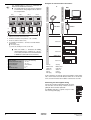
INSTALLATION MANUAL
Gateway option box
EKLONPG
EKBNPG
EKLONPG
EKBNPG
Installation manual
Gateway option box
CONTENTS
Page
Accessories....................................................................................... 1
Function ............................................................................................ 1
Name and function of parts ............................................................... 1
Selecting the installation site............................................................. 1
Mechanical installation ...................................................................... 2
FUNCTION
Up to 8 chiller units equipped with the EKACPG address card can be
controlled by the Lon Gateway or BACnet/IP Gateway.
The Lon Gateway and BACnet/IP Gateway enable interfacing
between the chiller unit and the Building Management System
(BMS).
Units installed in such configuration can be monitored and operated
on the BMS through LonWorks® or BACnet/IP communication.
Electric wiring work ........................................................................... 2
Precautions................................................................................................ 2
Connecting the wiring ................................................................................ 2
Examples of communication connections.................................................. 3
Connecting the field supplied wiring .......................................................... 3
NAME
AND FUNCTION OF PARTS
EKLONPG
Operation and maintenance.............................................................. 4
EKBNPG
What to do before operation ...................................................................... 4
Operation and display signals.................................................................... 4
Troubleshooting ................................................................................. 4
Maintenance...................................................................................... 4
READ THESE INSTRUCTIONS CAREFULLY BEFORE
INSTALLATION AND OPERATION.
IMPROPER INSTALLATION OR ATTACHMENT OF
EQUIPMENT OR ACCESSORIES COULD RESULT IN
ELECTRIC SHOCK, SHORT-CIRCUIT, LEAKS, FIRE OR
OTHER DAMAGE TO THE EQUIPMENT. BE SURE ONLY
TO USE ACCESSORIES MADE BY DAIKIN WHICH ARE
SPECIFICALLY DESIGNED FOR USE WITH THE
EQUIPMENT AND HAVE THEM INSTALLED BY A
PROFESSIONAL.
IF UNSURE OF INSTALLATION PROCEDURES OR USE,
ALWAYS CONTACT YOUR DAIKIN DEALER FOR
ADVICE AND INFORMATION.
ACCESSORIES
For EKLONPG: Lon
Gateway option box
For EKBNPG:
BACnet/IP Gateway
option box
Screw nut
1x
1
3
1x
2
5
5
4
9
6
9
6
7
7
2
(3x)
1
2
3
4
5
Option box
Hanger brackets
Lid
PCB
Transformer
2
(3x)
8
6
7
8
9
8
Terminal
Knock-out holes
Screw nut
Filter PCB with integrated fuse
3x
SELECTING
1x
Select an installation site where the following conditions are fulfilled
and that meets your customers approval.
Manual
Ferrite core V2C
1
3
4
■
Ferrite core V1C
(only for EKBNPG)
2
1x
THE INSTALLATION SITE
The option box must be installed indoors.
Do not install the option box in rooms:
■ where mineral oil, like cutting oil is present;
DIMENSIONS
■ where the air contains high levels of salt such as air near the
ocean;
Unit of measurement: mm
■ where sulphurous gas is present such as that in areas of hot
spring;
76
.2
■ in vehicles or vessels;
210
■ where voltage fluctuates a lot such as that in factories;
293
356.5
■ where high concentrations of vapour or spray are present;
230
Installation manual
1
■ where machines generating electromagnetic waves are
present;
■ where acidic or alkaline vapour is present.
■
Do not install the option box in or on the chiller unit.
■
Do not install the option box in direct sunlight. Direct sunlight will
increase the temperature inside the option box and may reduce
its lifetime and influence its operation.
■
Choose a flat and strong mounting surface.
■
Keep the space in front of the option box free for future
maintenance.
EKLONPG + EKBNPG
Gateway option box
4PW40333-1A
MECHANICAL
INSTALLATION
Connecting the wiring
■
The option box must always be installed with electrical
connections downward.
1
Open the lid of the option box.
2
Open the necessary knock-out holes.
3
Fix the option box with its hanger brackets to the mounting
surface.
Use 4 screws (for holes of Ø5 mm).
4
For electrical wiring: refer to paragraph "Electric wiring work" on
page 2.
5
Install the screw nuts with the ring outside the option box (see
drawing in chapter "Name and function of parts" on page 1).
6
Close the lid securely with all 5 screws after installation to
ensure that the option box is watertight.
ELECTRIC
EKLONPG
–+
All field wiring and components must be installed by a
licensed electrician and must comply with relevant
European and national regulations.
The field wiring must be carried out in accordance with the
wiring diagram supplied with the unit and the instructions
given below.
■
Use copper wire only.
■
A circuit breaker capable of shutting down power supply to the
entire system must be installed.
Precautions
Use only specified wires, and tightly connect wires to the terminals.
Keep wiring in neat order so that it does not obstruct other
equipment. Incomplete connections could result in overheating, and
in worse case electric shock or fire.
–+
–+
RS485 LON WORKS
–+ 1 2
V1C
L N
RS485
–+
2 3
L N
V2C
V2C
1
–+
FG
GND
POWER RS485
V3C
4
1
2
3
Field wiring
Shielded field wiring
1
2
3
4
■
Ethernet 10/100Base-T
connection for PC configuration
RS485 Modbus connection
LonWorks® connection
Power supply (Ferrite core V2C:
wind cables 1 time)
1
2
3
Ethernet 10/100Base-T
connection for BACnet/IP
communication and for
PC configuration (Ferrite core
V1C: wind cable 1 time)
RS485 Modbus connection
Power supply (Ferrite core V2C:
wind cables 1 time)
Connect cables according to specifications in the table below.
Connection to
LonWorks® network
Configuration PC
BACnet/IP
communication
RS485 Modbus
connection
Power supply
EKLONPG + EKBNPG
Gateway option box
4PW40333-1A
EKBNPG
FG
GND
POWER RS485
WIRING WORK
A main switch or other means for disconnection, having a
contact separation in all poles, must be incorporated in the
fixed wiring in accordance with relevant local and national
legislation.
Connect the wires to the terminal board according to the wiring
diagram and the figure below.
LonWorks® network communication wiring,
no polarity (shielded, connect shield to earth)
In case of communication via hub, use an
Ethernet 10/100Base-T straight cable
(field supply). (only for EKBNPG: shielded)
In case of direct communication use an
Ethernet 10/100Base-T cross cable
(field supply). (only for EKBNPG: shielded)
Use a 0.75~1.25 mm2 2-wire cable of
maximum 500 m measured from gateway to
last unit in line (+/– polarity) (shielded,
connect shield to earth).
Use a 2-wire + earth cable and perform
grounding.
Installation manual
2
Unit 1
Unit 2
Term. S3A
1
ON
Unit 3
Term. S3A
OFF
ON
Unit 4
Term. S3A
OFF
ON
Term. S3A
OFF
ON
OFF
or
Ethernet/BACnet (field syupply)
The wiring between the units must be performed
as shown on the wiring diagram and as shown in
the example below.
EKLONPG
Gateway
■
LonTalk® network (field supply)
Use shielded cables in case of a combination of
EKACPG with EKBNPG or EKLONPG.
Gateway
Examples of communication connections
NOTE
BMS
2
3
4
(*)
(*)
EKBNPG
(*)
≤500 m
Chiller unit 1
1 Setting of the S3A DIP switch on the PCB
2 Terminal on the address card (connect to + and – of RS485)
3 Ferrite core (wind the cables 2 times)
Address 01
■ = DIP switch setting
(*) Connect the shielding of the wires to each other
■
■
Make the RS485 +/– connection for Modbus
communication using a shielded 0.75~1.25 mm 2
2-wire cable (maximum of 500 m from EKLONPG
or EKBNPG to connection on last unit in line).
Modbus slaves
4 Up to EKBNPG or EKLONPG +/– terminals of the RS485 Modbus
communication
A11P
S3A
ON
OFF
Chiller unit 2
Address 02
A21P
A11P
S3A
ON
OFF
Chiller unit 3
A21P
Main specifications
Power supply
Relative humidity
Operating temperature range
Storage temperature
Power consumption
Weight
Maximum fuse amps
1N~ 230 V AC (50 Hz)
5~90%, non-condensing
–10~43°C
–20~70°C
10 W maximum
2.1 kg
6A
Address 03
Gateway
Gateway
Modbus slaves
Modbus slaves
Chiller unit 1
Chiller unit 1
Address 01
Address 01
network
network
field supply
field supply
A11P
S3A
ON
OFF
In these examples, the S3A DIP switch on the address card of chiller
units 1 and 2 must be set to OFF. Because chiller unit 3 is the last unit
in line, the S3A DIP switch on the address card must be set to ON.
Connecting the field supplied wiring
Pull the wires inside the option box through the screw
nuts and close the nuts firmly in order to ensure a
good pull relieve and water protection.
An additional pull-relief is required, strap the cables
with a tie wrap (field supply).
Installation manual
3
EKLONPG + EKBNPG
Gateway option box
4PW40333-1A
OPERATION
NOTES
AND MAINTENANCE
What to do before operation
■
Before initiating operation, contact your Daikin dealer
to get the service manual that corresponds to your
system.
■
For the chiller unit and the EKACPG address card
refer to the dedicated manual.
Operation and display signals
EKLONPG
EKBNPG
TX (1)
RX (1)
TX (1)
RX (1)
LA
TX (2)
RX (2)
RA0
PWR
(*)
PWR
PWR
PWR
LON
Colour
LED
PWR (2x) green
Lights up when power is connected
RX (1)
green
Flashes when receiving data via RS485 Modbus
TX (1)
green
Flashes when transmitting data via RS485 Modbus
only for Lon Gateway (EKLONPG)
LA
green
Flashes when the PCB is in normal operation
LON
red
Lights up when the Lon service pin(*) is pushed
green
Flashes when receiving data via LonTalk® network
RX (2)
TX (2)
green
Flashes when transmitting data via LonTalk® network
only for BACnet/IP Gateway (EKBNPG)
red
Flashes when the PCB is in normal operation
RA0
(*) Lon service pin: The network integrator will need to push the Lon service pin
during commissioning the LonTalk® network.
TROUBLESHOOTING
Consult the design guide of your system and contact your Daikin
dealer.
The system must be repaired by a qualified service
person.
MAINTENANCE
■
Only a qualified service person is allowed to perform
maintenance.
■
Before obtaining access to terminal devices, all power
supply circuits must be interrupted.
■
Water or detergent may deteriorate the insulation of
electronic components and result in burn-out of these
components.
EKLONPG + EKBNPG
Gateway option box
4PW40333-1A
Installation manual
4
4PW40333-1A
Copyright © Daikin