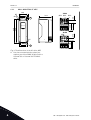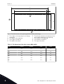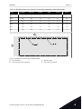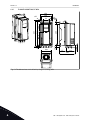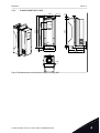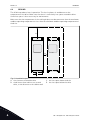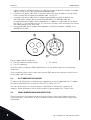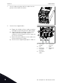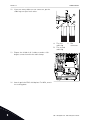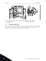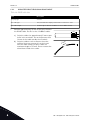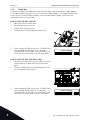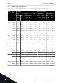
1
vacon 100
vacon 100 flow
®
®
ac drives
installation manual
PREFACE
VACON · 3
PREFACE
Document ID:
DPD00873E
Date:
3.4.2014
ABOUT THIS MANUAL
This manual is copyright of Vacon Plc. All Rights Reserved.
24-HOUR SUPPORT +358 (0)201 212 575 · EMAIL: [email protected]
VACON · 4
TEL. +358 (0)201 2121 · FAX +358 (0)201 212 205
TABLE OF CONTENTS
VACON · 5
TABLE OF CONTENTS
Preface
About this manual
3
1
Approvals
8
2
Safety
2.1
The safety symbols used in the manual
2.2
Warning
2.3
Caution
2.4
Earthing and earth fault protection
2.5
Electro-magnetic compatibility (EMC)
2.6
Using an RCD or an RCM device
10
10
10
11
12
13
13
3
Receiving the delivery
3.1
Package label
3.2
Type designation code
3.3
Unpacking and lifting the AC drive
3.3.1
Weight of the AC drive
3.3.2
Lifting the frames MR8 and MR9
3.4
Accessories
3.4.1
Frame MR4
3.4.2
Frame MR5
3.4.3
Frame MR6
3.4.4
Frame MR7
3.4.5
Frame MR8
3.4.6
Frame MR9
3.5
"Product modified" label
3.6
Disposal
14
14
14
15
15
15
16
17
17
18
19
19
20
20
20
4
Mounting
4.1
General information about mounting
4.2
Dimensions for wall mounting
4.2.1
Wall mounting of MR4
4.2.2
Wall mounting of MR5
4.2.3
Wall mounting of MR6
4.2.4
Wall mounting of MR7
4.2.5
Wall mounting of MR8, IP21 and IP54
4.2.6
Wall mounting of MR8, IP00
4.2.7
Wall mounting of MR9, IP21 and IP54
4.2.8
Wall mounting of MR9, IP00
21
21
21
21
22
23
24
25
26
27
28
24-HOUR SUPPORT +358 (0)201 212 575 · EMAIL: [email protected]
VACON · 6
TABLE OF CONTENTS
4.3
4.4
Dimensions for flange mounting
4.3.1
Flange mounting of MR4
4.3.2
Flange mounting of MR5
4.3.3
Flange mounting of MR6
4.3.4
Flange mounting of MR7
4.3.5
Flange mounting of MR8
4.3.6
Flange mounting of MR9
Cooling
28
32
33
34
35
36
37
38
5
Power cabling
5.1
Cable connections
5.2
UL standards on cabling
5.3
Cable dimensioning and selection
5.3.1
Cable and fuse sizes
5.3.2
Cable and fuse sizes, North America
5.4
Brake resistor cables
5.5
Preparing for the cable installation
5.6
Cable installation
5.6.1
Frames MR4 to MR7
5.6.2
Frames MR8 to MR9
5.7
Installation in a corner-grounded network
41
41
42
42
43
45
49
49
50
50
56
68
6
Control unit
6.1
Control unit components
6.2
Control unit cabling
6.2.1
Selection of the control cables
6.2.2
Control terminals and DIP switches
6.3
Fieldbus connection
6.3.1
Using fieldbus through an Ethernet cable
6.3.2
Using fieldbus through an RS485 cable
6.4
Installation of option boards
6.4.1
The installation procedure
6.5
Installation of a battery for the Real Time Clock (RTC)
6.6
Galvanic isolation barriers
69
69
70
70
70
74
75
78
82
83
85
85
7
Commissioning and additional instructions
7.1
Commissioning safety
7.2
Commissioning of the drive
7.3
Operation of the motor
7.3.1
Checks before starting the motor
7.4
Measuring the cable and motor insulation
7.5
Installation in an IT system
7.5.1
Frames MR4, MR5, and MR6
7.5.2
Frames MR7 and MR8
7.5.3
Frame MR9
7.6
Maintenance
87
87
87
88
88
88
89
89
91
94
95
TEL. +358 (0)201 2121 · FAX +358 (0)201 212 205
TABLE OF CONTENTS
VACON · 7
8
Technical data, Vacon® 100
8.1
AC drive power ratings
8.1.1
Mains voltage 208-240 V
8.1.2
Mains voltage 380-500 V
8.1.3
Overload capability
8.1.4
Brake resistor ratings
®
8.2
Vacon 100 - technical data
96
96
96
98
99
100
103
9
Technical data, Vacon® 100 FLOW
9.1
AC drive power ratings
9.1.1
Mains voltage 208-240 V
9.1.2
Mains voltage 380-500 V
9.1.3
Overload capability
®
9.2
Vacon 100 FLOW - technical data
107
107
107
108
109
110
10 Technical data on control connections
10.1 Technical data on control connections
114
114
24-HOUR SUPPORT +358 (0)201 212 575 · EMAIL: [email protected]
VACON · 8
1
APPROVALS
APPROVALS
Here are the approvals that have been granted to this Vacon product.
1.
2.
3.
1
EC Declaration of conformity
• Find the EC Declaration of Conformity on the next page.
UL approval
• cULus approval file number E171278.
C-tick approval
• C-tick approval file number N16307.
TEL. +358 (0)201 2121 · FAX +358 (0)201 212 205
APPROVALS
VACON · 9
EC DECLARATION OF CONFORMITY
We
Manufacturer’s name:
Vacon Oyj
Manufacturer’s address:
P.O. Box 25
Runsorintie 7
FIN-65381 Vaasa
Finland
hereby declare that the product
Product name:
Vacon 100 AC drive
Model designation:
Vacon 0100-3L-0003-5...0310-5
Vacon 0100-3L-0003-2...0310-2
has been designed and manufactured in accordance with the following standards:
Safety:
EN 61800-5-1: 2007
EN 60204-1: 2009 (as relevant)
EMC:
EN 61800-3: 2004 + A1: 2012
EN 61000-3-12
and conforms to the relevant safety provisions of the Low Voltage Directive
(2006/95/EC) and EMC Directive 2004/108/EC.
It is ensured through internal measures and quality control that the product
conforms at all times to the requirements of the current Directive and the relevant
standards.
In Vaasa, 26th of February, 2014
Vesa Laisi
President
The year the CE marking was affixed:
2012
24-HOUR SUPPORT +358 (0)201 212 575 · EMAIL: [email protected]
1
VACON · 10
SAFETY
2
SAFETY
2.1
THE SAFETY SYMBOLS USED IN THE MANUAL
This manual contains warnings and cautions, which are identified with safety symbols. The
warnings and cautions give important information on how to prevent injury and damage to
the equipment or your system.
Read the warnings and cautions carefully and obey their instructions.
Table 1: The safety symbols
The safety symbol
Description
WARNING!
CAUTION!
HOT SURFACE!
2.2
WARNING
WARNING!
Do not touch the components of the power unit when the drive is connected to
mains. The components are live when the drive is connected to mains. A contact
with this voltage is very dangerous.
WARNING!
Do not touch the motor terminals U, V, W or the brake resistor terminals when the
drive is connected to mains. These terminals are live when the drive is connected to
mains, also when the motor does not operate.
WARNING!
Do not touch the relay outputs or the I/O terminals. They can have a dangerous
voltage also when the drive is disconnected from mains.
2
TEL. +358 (0)201 2121 · FAX +358 (0)201 212 205
SAFETY
VACON · 11
WARNING!
Before you do electrical work, make sure that there is no voltage in the
components of the drive.
WARNING!
To do work on the terminal connections of the drive, disconnect the drive from
mains and make sure that the motor has stopped. Wait 5 minutes before you open
the cover of the drive. Then use a measuring device to make sure that there is no
voltage. The terminal connections and the components of the drive are live 5
minutes after it is disconnected from mains and the motor has stopped.
WARNING!
Before you connect the drive to mains, make sure that the front cover and the cable
cover of the drive are closed. The connections of the AC drive are live when the
drive is connected to mains.
WARNING!
Disconnect the motor from the drive if an accidental start can be dangerous. When
there is a power-up, a power brake or a fault reset, the motor starts immediately if
the start signal is active, unless the pulse control for Start/Stop logic is selected. If
the parameters, the applications or the software change, the I/O functions
(including the start inputs) can change.
2.3
CAUTION
CAUTION!
Do not move the AC drive. Use a fixed installation to prevent damage to the drive.
CAUTION!
Do not make measurements when the AC drive is connected to mains. It can cause
damage to the drive.
CAUTION!
Make sure that there is reinforced protective ground connection. It is mandatory,
because the touch current of the AC drives is more than 3.5 mA AC (refer to EN
61800-5-1). See chapter 2.4 Earthing and earth fault protection.
CAUTION!
Do not use spare parts that are not from the manufacturer. Using other spare parts
can cause damage to the drive.
CAUTION!
Do not touch the components on the circuit boards. Static voltage can cause
damage to these components.
24-HOUR SUPPORT +358 (0)201 212 575 · EMAIL: [email protected]
2
VACON · 12
SAFETY
CAUTION!
Make sure that the EMC level of the AC drive is correct for your mains. See chapter
7.5 Installation in an IT system. An incorrect EMC level can cause damage to the
drive.
CAUTION!
Prevent radio interference. The AC drive can cause radio interference in a domestic
environment.
NOTE!
If you activate the autoreset function, the motor starts automatically after an
automatic fault reset. See the Application Manual.
NOTE!
If you use the AC drive as a part of a machine, the machine manufacturer must
supply a mains disconnection device (refer to EN 60204-1).
2.4
EARTHING AND EARTH FAULT PROTECTION
CAUTION!
The AC drive must always be earthed with an earth conductor that is connected to
the earth terminal that is identified with the symbol . Not using an earth
conductor can cause damage to the drive.
The touch current of the drive is more than 3.5 mA AC. The standard EN 61800-5-1 tells that
1 or more of these conditions for the protective circuit must be true.
The connection must be fixed.
a) The protective earth conductor must have a cross-sectional area of minimum 10 mm2 Cu
or 16 mm2 Al. OR
b) There must be an automatic disconnection of the mains, if the protective earth conductor
breaks. See chapter 5 Power cabling. OR
c) There must be a terminal for a second protective earth conductor in the same crosssectional area as the first protective earth conductor.
Table 2: Protective earthing conductor cross-section
Cross-sectional area of the phase conductors (S)
[mm2]
The minimum cross-sectional area of the protective
earthing conductor in question [mm2]
S ≤ 16
S
16 < S ≤ 35
16
35 < S
S/2
The values of the table are valid only if the protective earthing conductor is made of the same
metal as the phase conductors. If this is not so, the cross-sectional area of the protective
2
TEL. +358 (0)201 2121 · FAX +358 (0)201 212 205
SAFETY
VACON · 13
earthing conductor must be determined in a manner that produces a conductance equivalent
to that which results from the application of this table.
The cross-sectional area of each protective earthing conductor that is not a part of the mains
cable or the cable enclosure, must be a minimum of:
•
•
2.5 mm2 if there is mechanical protection, and
4 mm2 if there is not mechanical protection. If you have cord-connected equipment,
make sure that the protective earthing conductor in the cord is the last conductor to be
interrupted, if the strain-relief mechanism breaks.
Obey the local regulations on the minimum size of the protective earthing conductor.
NOTE!
Because there are high capacitive currents in the AC drive, it is possible that the
fault current protective switches do not operate correctly.
CAUTION!
Do not do voltage withstand tests on the AC drive. The manufacturer has already
done the tests. Doing voltage withstand tests can cause damage to the drive.
2.5
ELECTRO-MAGNETIC COMPATIBILITY (EMC)
The drive must obey the standard IEC 61000-3-12. To obey it, the short-circuit power SSC
must be a minimum of 120 RSCE at the interface point between your mains and the public
mains. Make sure that you connect the drive and the motor to mains with a short-circuit
power SSC that is a minimum of 120 RSCE. If necessary, contact your mains operator.
2.6
USING AN RCD OR AN RCM DEVICE
The drive can cause a current in the protective earthing conductor. You can use a residual
current-operated protective (RCD) device, or a residual current-operated monitoring (RCM)
device to give protection against a direct or an indirect contact. Use a type B RCD or RCM
device on the mains side of the drive.
NOTE! You can download the English and French product manuals with applicable safety, warning and caution
information from www.vacon.com/downloads.
REMARQUE Vous pouvez télécharger les versions anglaise et française des manuels produit contenant l'ensemble des informations de sécurité, avertissements et mises en garde applicables sur le site www.vacon.com/
downloads.
24-HOUR SUPPORT +358 (0)201 212 575 · EMAIL: [email protected]
2
VACON · 14
RECEIVING THE DELIVERY
3
RECEIVING THE DELIVERY
3.1
PACKAGE LABEL
To make sure that the delivery is correct, compare your order data to the data on the
package label. If the delivery does not agree with your order, speak to the vendor
immediately.
A
B
C
D
E
F
G
H
I
Fig. 1: The package label of Vacon AC drives
A.
B.
C.
D.
E.
3.2
The batch ID
The order number of Vacon
The type designation code
The serial number
The mains voltage
F.
G.
H.
I.
The rated output current
The IP class
The application code
The order number of the customer
TYPE DESIGNATION CODE
The type designation code of Vacon is made of standard codes and optional codes. Each part
of the type designation code agrees to the data in your order. The code can have this format,
for example:
VACON0100-3L-0061-5+IP54
VACON0100-3L-0061-5-FLOW
3
TEL. +358 (0)201 2121 · FAX +358 (0)201 212 205
RECEIVING THE DELIVERY
VACON · 15
Table 3: The description of the parts in the type designation code
Code
Description
VACON
This part is same for all the products.
0100
The product range: 0100 = Vacon 100
3L
Input/Function: 3L = A 3-phase input
0061
The drive rating in amperes. For example, 0061 = 61 A
5
The mains voltage:
2 = 208-240 V
5 = 380-500 V
FLOW
The Vacon 100 FLOW AC drive
+IP54
The optional codes. There are many options, for example +IP54 (an AC drive with
the IP protection class IP54)
3.3
UNPACKING AND LIFTING THE AC DRIVE
3.3.1
WEIGHT OF THE AC DRIVE
The weights of AC drives of different frames are very different. It can be necessary for you to
use a lifting device to move the drive from its package.
Table 4: The weights of the different frames
Frame
Weight, IP21/IP54
[kg]
Weight, IP00 [kg]
Weight, UL Type 1 /
Type 12 [lb.]
Weight, UL Open
Type [lb.]
MR4
6.0
13.2
MR5
10.0
22.0
MR6
20.0
44.1
MR7
37.5
82.7
MR8
66.0
62.0
145.5
136.7
MR9
119.5
103.5
263.5
228.2
3.3.2
1
2
LIFTING THE FRAMES MR8 AND MR9
Remove the drive from the pallet where it was
bolted to.
Use a lifting device that is sufficiently strong for the
weight of the drive.
24-HOUR SUPPORT +358 (0)201 212 575 · EMAIL: [email protected]
3
VACON · 16
3
4
RECEIVING THE DELIVERY
Put the lifting hooks symmetrically in a minimum of
2 holes.
The maximum lifting angle is 45 degrees.
≤45°
Before a Vacon® AC drive is sent to the customer, the manufacturer makes many tests on
the drive. After you lift the drive, do a check for signs of damage on the drive. Make sure that
the contents of the package are correct.
If the drive was damaged during the shipping, speak to the cargo insurance company or the
carrier.
3.4
ACCESSORIES
After you open the package and lift the drive out, make sure that you received all the
accessories. The content of the accessories bag is different for the different frames and
protection classes.
3
TEL. +358 (0)201 2121 · FAX +358 (0)201 212 205
RECEIVING THE DELIVERY
3.4.1
VACON · 17
FRAME MR4
Table 5: The content of accessories bag
Item
Quantity
Description
M4x16 screw
11
Screws for the power cable clamps (6), the
control cable clamps (3), and the grounding
clamps (2)
M4x8 screw
1
Screw for the optional grounding
M5x12 screw
1
Screw for the external grounding of the drive
Control cable grounding lamella
3
Control cable grounding
EMC cable clamp, size M25
3
Clamping the power cables
Grounding clamp
2
Power cable grounding
"Product modified" label
1
Data about changes
IP21: Cable grommet
3
Sealing for the cables
IP54: Cable grommet
6
Sealing for the cables
3.4.2
FRAME MR5
Table 6: The content of the accessories bag
Item
Quantity
Description
M4x16 screw
13
Screws for the power cable clamps (6), the
control cable clamps (3), and the grounding
clamps (4)
M4x8 screw
1
Screw for the optional grounding
M5x12 screw
1
Screw for the external grounding of the drive
Control cable grounding lamella
3
Control cable grounding
EMC cable clamps, size M25
1
Clamping brake cable
EMC cable clamps, size M32
2
Clamping power cables
Grounding clamp
2
Power cable grounding
"Product modified" label
1
Data about changes
IP21: Cable grommet, hole diameter 25.3 mm
1
Sealing for the cables
IP54: Cable grommet, hole diameter 25.3 mm
4
Sealing for the cables
Cable grommet, hole diameter 33.0 mm
2
Sealing for the cables
24-HOUR SUPPORT +358 (0)201 212 575 · EMAIL: [email protected]
3
VACON · 18
3.4.3
RECEIVING THE DELIVERY
FRAME MR6
Table 7: The content of the accessories bag
Item
Quantity
Description
M4x20 screw
10
Screws for the power cable clamps (6), and
the grounding clamps (4)
M4x16 screw
3
Screws for the control cable clamps
M4x8 screw
1
Screw for the optional grounding
M5x12 screw
1
Screw for the external grounding of the drive
Control cable grounding lamella
3
Control cable grounding
EMC cable clamps, size M32
1
Clamping the brake resistor cable
EMC cable clamps, size M40
2
Clamping the power cables
Grounding clamp
2
Power cable grounding
"Product modified" label
1
Data about changes
Cable grommet, hole diameter 33.0 mm
1
Sealing for the cables
Cable grommet, hole diameter 40.3 mm
2
Sealing for the cables
IP54: Cable grommet, hole diameter 25.3 mm
3
Sealing for the cables
NOTE!
The Vacon® 100 FLOW software does not have the dynamic braking or the brake
resistor functions.
3
TEL. +358 (0)201 2121 · FAX +358 (0)201 212 205
RECEIVING THE DELIVERY
3.4.4
VACON · 19
FRAME MR7
Table 8: The content of the accessories bag
Item
Quantity
Description
M6x30 slotted nut
6
Nuts for the power cable clamps
M4x16 screw
3
Screws for the control cable clamps
M6x12 screw
1
Screw for the external grounding of the drive
Control cable grounding lamella
3
Control cable grounding
EMC cable clamps, size M25
3
Clamping the power cables
Grounding clamp
2
Power cable grounding
‘Product modified’ label
1
Data about changes
IP21: Cable grommet
3
Sealing for the cables
IP54: Cable grommet
3
Sealing for the cables
3.4.5
FRAME MR8
Table 9: The content of accessories bag
Item
Quantity
Description
M4x16 screw
3
Screws for the control cable clamps
Control cable grounding lamella
3
Control cable grounding
Cable lugs KP40
3
Clamping power cables
Cable insulator
11
To prevent contact between cables
Cable grommet, hole diameter 25.3 mm
4
Sealing for the cables
IP00: Touch shield
1
To prevent contact with live parts
IP00: M4x8 screw
2
To attach the touch protection shield
24-HOUR SUPPORT +358 (0)201 212 575 · EMAIL: [email protected]
3
VACON · 20
3.4.6
RECEIVING THE DELIVERY
FRAME MR9
Table 10: The content of the accessories bag
Item
Quantity
Description
M4x16 screw
3
Screws for the control cable clamps
Control cable grounding lamella
3
Control cable grounding
Cable lugs KP40
5
Clamping power cables
Cable insulator
10
To prevent contact between cables
Cable grommet, hole diameter 25.3 mm
4
Sealing for the cables
IP00: Touch shield
1
To prevent contact with live parts
IP00: M4x8 screw
2
To attach the touch protection shield
3.5
"PRODUCT MODIFIED" LABEL
In the accessories bag, there is also a "product modified" label. The function of the label is to
tell the service personnel about the changes that are made in the AC drive. Attach the label
on the side of the AC drive to know where to find it. If you make changes in the AC drive, write
the change on the label.
Product modified
Date:
Date:
Date:
3.6
DISPOSAL
When the drive is at the end of its operation life, do not discard it as a part of municipal
waste. You can recycle the primary components of the drive. You must disassemble
some components before you can remove the different materials. Recycle the electrical
and electronic components as waste.
To make sure that the waste is recycled correctly, send the waste to a recycling centre.
You can also send the waste back to the manufacturer.
Obey the local and other applicable regulations.
3
TEL. +358 (0)201 2121 · FAX +358 (0)201 212 205
MOUNTING
VACON · 21
4
MOUNTING
4.1
GENERAL INFORMATION ABOUT MOUNTING
Install the AC drive in a vertical position on the wall. If you install the drive in a horizontal
position, it is possible that some functions with the nominal values that are found in chapter
8 Technical data, Vacon® 100 or 9 Technical data, Vacon® 100 FLOW are not available.
Attach the AC drive with the screws and other components that you received in the delivery.
4.2
DIMENSIONS FOR WALL MOUNTING
4.2.1
WALL MOUNTING OF MR4
Ø7
128
100
190
IP21
Ø13
112
IP54
147
Ø25
112
328
313
151
Ø25
100
Fig. 2: The dimensions of the AC drive, MR4
24-HOUR SUPPORT +358 (0)201 212 575 · EMAIL: [email protected]
4
VACON · 22
144
115
100*
Ø7
IP21
214
Ø33 Ø25
A
Ø33
IP54
Ø25
37.5
419
406
130
134
Ø7
Ø14
WALL MOUNTING OF MR5
39
4.2.2
MOUNTING
100*
115
A
130
134
Ø7
Fig. 3: The dimensions of the AC drive, MR5
A. Use these mounting holes when you
replace your Vacon® NX AC drive with a
Vacon® 100 or Vacon® 100 FLOW AC
drive.
4
TEL. +358 (0)201 2121 · FAX +358 (0)201 212 205
MOUNTING
WALL MOUNTING OF MR6
195
148
229
IP21
Ø40 Ø33
Ø40
557
541
148
151
Ø9
Ø15.5
43.7
4.2.3
VACON · 23
IP54
Ø9
151
148
42
Ø25
148
Fig. 4: The dimensions of the AC drive, MR6
24-HOUR SUPPORT +358 (0)201 212 575 · EMAIL: [email protected]
4
VACON · 24
4.2.4
MOUNTING
WALL MOUNTING OF MR7
237
190
259
Ø9
Ø16
IP21
Ø51
645
660
160
211
Ø20
Ø25
IP54
160
217
Ø50
Fig. 5: The dimensions of the AC drive, MR7
4
TEL. +358 (0)201 2121 · FAX +358 (0)201 212 205
MOUNTING
WALL MOUNTING OF MR8, IP21 AND IP54
188
164
3 x 38
114
117
Ø25
62.5
Ø60
9
22
663
217
Ø11
343
262
216
Ø9
235
4.2.5
VACON · 25
Ø9
Ø22
290
996
Fig. 6: The dimensions of the AC drive, MR8, IP21 and IP54
24-HOUR SUPPORT +358 (0)201 212 575 · EMAIL: [email protected]
4
VACON · 26
MOUNTING
4.2.6
WALL MOUNTING OF MR8, IP00
215.7
663
217
255
9.3
Ø9
Ø11
Ø9
10.8
343
171.5
186.5
Ø22
683
15.1
290
18
794
Fig. 7: The dimensions of the AC drive, MR8, IP00
4
TEL. +358 (0)201 2121 · FAX +358 (0)201 212 205
MOUNTING
4.2.7
VACON · 27
WALL MOUNTING OF MR9, IP21 AND IP54
166
318
360
Ø25
77
84
4 x 81.5
326
3 x 42
126
Ø59
Ø9
284
27,5
292
365
355
810
Ø9
480
400
M8 GND
360
Ø22
Ø9
Ø9
1122
1150
14
Fig. 8: The dimensions of the AC drive, MR9, IP21 and IP54
24-HOUR SUPPORT +358 (0)201 212 575 · EMAIL: [email protected]
4
VACON · 28
4.2.8
MOUNTING
WALL MOUNTING OF MR9, IP00
360
480
400
50
Ø9
Ø9
810
14
16.5
840.5
A
Ø22
M8
72
8 x 42
336
M8
GND
65
Ø25
3 X 42
84.5 126
365
355
130
318
Fig. 9: The dimensions of the AC drive, MR9, IP00
A. An optional main connector cover for the
cabinet installation
4.3
DIMENSIONS FOR FLANGE MOUNTING
You can also install the AC drive into the cabinet wall with a flange mounting option.
4
TEL. +358 (0)201 2121 · FAX +358 (0)201 212 205
MOUNTING
VACON · 29
NOTE!
The protection classes are different in different sections of the drive.
A
A
B
C
E
D
Fig. 10: Example of flange mounting (frame MR9)
A. The cabinet wall or other surface
B. The front
C. The rear
D. IP00 / UL Open Type
E. IP54 / UL Type 12
24-HOUR SUPPORT +358 (0)201 212 575 · EMAIL: [email protected]
4
VACON · 30
MOUNTING
C
A
E
F
D
B
H
G
Fig. 11: The dimensions of the opening and drive outline with flange
A. The height of the opening for the flange
mounting
B. The width of the opening
C. The height of the drive
D. The width of the drive
E. The distance between the bottom of the
drive and the bottom of the opening
F. The outline of the opening
G. The outline of the drive
H. The top of the drive
Table 11: The dimensions of the drive, frames MR4 to MR9
Frame
4
C [mm]
D [mm]
C [in]
D [in]
MR4
357
152
14.1
6.0
MR5
454
169
17.9
6.7
MR6
580
220
22.8
8.7
MR7
680
286
26.8
11.3
MR8
898
359
35.4
14.1
MR9
1060
550
41.7
21.7
TEL. +358 (0)201 2121 · FAX +358 (0)201 212 205
MOUNTING
VACON · 31
Table 12: The dimensions of the opening for the flange mounting, frames MR4 to MR9
Frame
A [mm]
B [mm]
E [mm]
A [in]
B [in]
E [in]
MR4
315
137
24
12.4
5.4
0.9
MR5
408
152
23
16.1
6.0
0.9
MR6
541
203
23
21.3
8.0
0.9
MR7
655
240
13
25.8
9.4
0.5
MR8
859
298
18
33.8
11.7
0.7
MR9
975
485
54
38.4
19.1
2.1
A
D
Fig. 12: Sealing of the opening for MR8 and MR9
A. The AC drive
B. The outline of the opening
C. Gasket tape
D. The top of the drive
24-HOUR SUPPORT +358 (0)201 212 575 · EMAIL: [email protected]
4
VACON · 32
4.3.1
MOUNTING
FLANGE MOUNTING OF MR4
152
122
15
134
128
113
77
32.8
9
18.5
186.9
285
357
341
102
39
72
24
Ø7
190
Fig. 13: The dimensions of the AC drive, flange mounting, MR4
4
TEL. +358 (0)201 2121 · FAX +358 (0)201 212 205
MOUNTING
FLANGE MOUNTING OF MR5
11.5
39
145
72
24
4.3.2
VACON · 33
27.5
262.5
382
454.1
436
102
Ø7
9
12
145
169
33
13
Ø7
100
114
214
144
150
Fig. 14: The dimensions of the AC drive, flange mounting, MR5
24-HOUR SUPPORT +358 (0)201 212 575 · EMAIL: [email protected]
4
VACON · 34
4.3.3
MOUNTING
FLANGE MOUNTING OF MR6
36.4
12
72
196
26.2
115.5
514
566
Ø4
6
355.6
580
102
Ø7
184
220
232
16.8
18
106
123
229
13.9
Ø7
201
195
Fig. 15: The dimensions of the AC drive, flange mounting, MR6
4
TEL. +358 (0)201 2121 · FAX +358 (0)201 212 205
MOUNTING
4.3.4
VACON · 35
FLANGE MOUNTING OF MR7
110.4 148.8
51.2
197.5
680
720
35.2
192.5
441.6
660
192.5
Ø5.5
102
7.5
271
237
72
20.3
286
230
Fig. 16: The dimensions of the AC drive, flange mounting, MR7
24-HOUR SUPPORT +358 (0)201 212 575 · EMAIL: [email protected]
4
VACON · 36
FLANGE MOUNTING OF MR8
233
4.3.5
MOUNTING
26
19.4
89.6
82.5
852.6
890.8
831.5
573.5
Ø7
6.8
326
359
Ø7
72
334
182.5
315.5
Ø7
Ø6.5
424.7
102
898
1.9
293
GND M8
109.5
Fig. 17: The dimensions of the AC drive, flange mounting, MR8
4
TEL. +358 (0)201 2121 · FAX +358 (0)201 212 205
MOUNTING
4.3.6
VACON · 37
FLANGE MOUNTING OF MR9
108
247
255.8
Ø22
163
56
1039
300
300
Ø6.5
75
10.5
73
10.5
85
72
175
525
550
175
M8
GND
102
397.5
1060
120
3 x 42
126
449
Ø25
210
108.5
Fig. 18: The dimensions of the AC drive, flange mounting, MR9
24-HOUR SUPPORT +358 (0)201 212 575 · EMAIL: [email protected]
4
VACON · 38
4.4
MOUNTING
COOLING
The AC drive produces heat in operation. The fan circulates air and decreases the
temperature of the drive. Make sure that there is sufficiently free space around the drive.
Some free space is also necessary for maintenance.
C
Make sure that the temperature of the cooling air does not become more than the maximum
ambient operating temperature or less than the minimum ambient operating temperature of
the drive.
B
D
A
Fig. 19: Installation space
A. the clearance around the drive
B. the distance from a drive to a second
drive, or the distance to the cabinet wall
4
C. the free space above the drive
D. the free space below the drive
TEL. +358 (0)201 2121 · FAX +358 (0)201 212 205
MOUNTING
VACON · 39
Table 13: The minimum clearances around the AC drive
Minimum clearance [mm]
Minimum clearance [in]
Frame
A*
B*
C
D
A*
B*
C
D
MR4
20
20
100
50
0.8
0.8
3.9
2.0
MR5
20
20
120
60
0.8
0.8
4.7
2.4
MR6
20
20
160
80
0.8
0.8
6.3
3.1
MR7
20
20
250
100
0.8
0.8
9.8
3.9
MR8
20
20
300
150
0.8
0.8
11.8
5.9
MR9
20
20
350
200
0.8
0.8
13.8
7.9
* = For a drive with IP54 / UL Type 12, the minimum clearances A and B are 0 mm / 0 in.
Table 14: The necessary quantity of cooling air
Frame
The quantity of cooling
air [m3/h]
The quantity of cooling
air [CFM]
MR4
45
26.5
MR5
75
44.1
MR6
190
111.8
MR7
185
108.9
MR8
335
197.2
MR9
621
365.5
24-HOUR SUPPORT +358 (0)201 212 575 · EMAIL: [email protected]
4
MOUNTING
C+D
VACON · 40
Fig. 20: The installation space when drives are installed on top of each other
If you install many drives above each other
1.
2.
3.
4
The necessary free space is C + D.
Make the outlet air of the lower unit go away from the air intake of the upper unit. To do
this, attach a metal plate to the cabinet wall between the drives.
When you install the drives in a cabinet, make sure that you prevent recirculation of air.
TEL. +358 (0)201 2121 · FAX +358 (0)201 212 205
POWER CABLING
VACON · 41
5
POWER CABLING
5.1
CABLE CONNECTIONS
The mains cables are connected to terminals L1, L2 and L3. The motor cables are connected
to terminals U, V and W.
A
B
C
V/T2
L3
W/T3
R-
L2
DC+/R+
U/T1
DC-
L1
Fig. 21: The principal connection diagram
A. The control panel
B. The control unit
C. The power unit
Use cables with a minimum heat resistance of +70 °C (158 °F). In the selection of the cables
and the fuses, refer to the nominal output current of the drive. You can find the nominal
output current on the rating plate.
Table 15: The selection of the correct cable
Cable type
EMC requirements
1st environment
2nd environment
Category C2
Category C3
Category C4
The mains cable
1
1
1
The motor cable
3*
2
2
The control cable
4
4
4
24-HOUR SUPPORT +358 (0)201 212 575 · EMAIL: [email protected]
5
VACON · 42
1.
2.
3.
4.
POWER CABLING
A power cable for a fixed installation. A cable for the specified mains voltage. A shielded
cable is not necessary. We recommend an MCMK cable.
A symmetrical power cable with a concentric protection wire. A cable for the specified
mains voltage. We recommend an MCMK cable. See Fig. 22.
A symmetrical power cable with a compact low-impedance shield. A cable for the
specified mains voltage. We recommend an MCCMK, or an EMCMK cable. We
recommend that the cable transfer impedance (1...30MHz) is a maximum of 100 mΩ/m.
See Fig. 22. * = For the EMC level C2, it is necessary to have a 360º earthing of the shield
with cable glands in the motor end.
A screened cable with a compact low-impedance shield, for example a JAMAK, or an
SAB/ÖZCuY-O cable.
B
A
C
Fig. 22: Cables with PE conductors
A. The PE conductor and the shield
B. The PE conductors
C. The shield
In all the frames, to obey the EMC requirements, use the default values of the switching
frequencies.
If you installed a safety switch, make sure that the EMC protection continues from the start
of the cables until their ends.
5.2
UL STANDARDS ON CABLING
To obey the UL (Underwriters Laboratories) regulations, use a UL-approved Class 1 copper
wire with a minimum heat resistance of 60 or 75 °C (140 or 167 °F).
You can use the drive on a circuit that gives a maximum of 100 000 rms symmetrical
amperes, and a maximum of 600 V, when the drive is protected by Class T and J fuses.
5.3
CABLE DIMENSIONING AND SELECTION
These instructions are valid only for processes that have 1 motor and 1 cable connection
from the AC drive to the motor. In other conditions, speak to the manufacturer to get more
information.
5
TEL. +358 (0)201 2121 · FAX +358 (0)201 212 205
POWER CABLING
5.3.1
VACON · 43
CABLE AND FUSE SIZES
We recommend the fuse type gG/gL (IEC 60269-1). To make a selection of the fuse voltage
rating, refer to the mains. Do not use larger fuses than what is recommended Table 16.
Make sure that the operation time of the fuse is less than 0.4 seconds. The operation time
agrees with the fuse type and the impedance of the supply circuit. For more information on
faster fuses, speak to the manufacturer. The manufacturer can also recommend some aR
(UL recognised, IEC 60269-4) and gS (IEC 60269-4) fuse ranges.
The table also shows the typical sizes and types of cables that can be used with the AC drive.
In the selection of cables, refer to local regulations, cable installation conditions and cable
specification.
NOTE!
The Vacon® 100 FLOW software does not have the dynamic braking or the brake
resistor functions.
24-HOUR SUPPORT +358 (0)201 212 575 · EMAIL: [email protected]
5
VACON · 44
POWER CABLING
Table 16: The cable and fuse sizes for Vacon® 100
Frame
Type
IL [A]
0003 2—0004 2
0003 5—0004 5
3.7—4.8
3.4—4.8
0006 2—0008 2
0005 5—0008 5
6.6—8.0
5.6—8.0
0011 2—0012 2
0009 5—0012 5
11.0—12.5
9.6—12.0
0018 2
0016 5
18.0
16.0
Fuse
(gG/gL)
[A]
Mains, motor and
brake resistor*
cable Cu [mm2]
6
3x1.5+1.5
0024 2
0023 5
24.0
23.0
0031 2
0031 5
31.0
31.0
0038 5
38.0
0048 2
0046 5
48.0
46.0
0062 2
0061 5
62.0
61.0
0075 2
0072 5
75.0
72.0
0088 2
0087 5
88.0
87.0
20
3x6+6
1—10 Cu
1-10
25
3x6+6
1—10 Cu
1-10
32
3x10+10
1—10 Cu
1-10
40
3x10+10
2.5—50 Cu/Al
2.5-35
2.5—50 Cu/Al
2.5-35
2.5—50 Cu/Al
2.5-35
6-70 mm2
Cu/Al
6-70 mm2
6-70 mm2
Cu/Al
6-70 mm2
6-70 mm2
Cu/Al
6-70 mm2
3x16+16 (Cu)
3x25+16 (Al)
3x25+16 (Cu)
3x35+10 (Al)
3x35+16 (Cu)
3x50+16 (Al)
100
0105 2
0105 5
5
1-6
1—6 solid
1—4 stranded
80
105.0
1-6
3x2.5+2.5
63
MR7
1-6
3x1.5+1.5
50
MR6
Earth terminal
[mm2]
1—6 solid
1—4 stranded
16
MR5
Main terminal
[mm2]
1—6 solid
1—4 stranded
10
MR4
Terminal cable size
3x35+16 (Cu)
3x70+21 (Al)
125
3x50+25 (Cu)
3x70+21 (Al)
TEL. +358 (0)201 2121 · FAX +358 (0)201 212 205
POWER CABLING
VACON · 45
Table 16: The cable and fuse sizes for Vacon® 100
Frame
Type
IL [A]
140.0
Fuse
(gG/gL)
[A]
160
0140 2
0140 5
200
0170 2
0170 5
250
0205 2
0205 5
Earth terminal
[mm2]
Bolt size M8
Bolt size M8
Bolt size M8
Bolt size M8
Bolt size M8
Bolt size M8
Bolt size M10
Bolt size M8
Bolt size M10
Bolt size M8
3x120+70 (Cu)
3x185+57 (Al)
261.0
315
0261 2
0261 5
3x185+95 (Cu)
2x3x120+41 (Al)
310.0
0310 2
0310 5
Main terminal
[mm2]
3x95+50 (Cu)
3x150+41 (Al)
205.0
MR9
Terminal cable size
3x70+35 (Cu)
3x95+29 (Al)
170.0
MR8
Mains, motor and
brake resistor*
cable Cu [mm2]
350
2x3x95+50 (Cu)
2x3x120+41 (Al)
* = If you use a multi-conductor cable, 1 of the conductors of the brake resistor cable stays
unconnected. It is also possible to use a single cable if you obey the minimum crosssectional area of the cable.
The dimensions of the cables must agree with the requirements of the standard
IEC60364-5-52.
•
•
•
•
•
The cables must be PVC-isolated.
The maximum ambient temperature is +30 °C (86 °F).
The maximum temperature of the cable surface is +70 °C (158 °F).
Use only cables with a concentric copper shield.
The maximum number of parallel cables is 9.
When you use parallel cables, make sure that you obey the requirements of the crosssectional area and the maximum number of cables.
For important information on the requirements of the earth conductor, see chapter 2.4
Earthing and earth fault protection.
For the correction factors for each temperature, see the standard IEC60364-5-52.
5.3.2
CABLE AND FUSE SIZES, NORTH AMERICA
We recommend the fuse class T (UL & CSA). To make a selection of the fuse voltage rating,
refer to the mains. Refer also to local regulations, cable installation conditions and cable
specification. Do not use larger fuses than what is recommended Table 17.
24-HOUR SUPPORT +358 (0)201 212 575 · EMAIL: [email protected]
5
VACON · 46
POWER CABLING
Make sure that the operation time of the fuse is less than 0.4 seconds. The operation time
agrees with the fuse type and the impedance of the supply circuit. For more information on
faster fuses, speak to the manufacturer. The manufacturer can also recommend some high
speed Class J (UL & CSA ) and aR (UL recognised) fuse ranges.
The solid state short circuit protection does not supply protection for the branch circuit of the
AC drive. To supply the branch circuit protection, refer to the National Electric Code and the
local regulations. Do not use other devices than fuses to supply branch circuit protection.
NOTE!
The Vacon® 100 FLOW software does not have the dynamic braking or the brake
resistor functions.
5
TEL. +358 (0)201 2121 · FAX +358 (0)201 212 205
POWER CABLING
VACON · 47
Table 17: The cable and fuse sizes for Vacon® 100 in North America
Frame
Type
Fuse
(Class
T/J) [A]
Mains, motor and
brake resistor*
cable Cu [AWG]
Terminal cable size
Main terminal
[AWG]
Earth terminal
[AWG]
6
AWG14
AWG24-AWG10
AWG17-AWG10
6
AWG14
AWG24-AWG10
AWG17-AWG10
10
AWG14
AWG24-AWG10
AWG17-AWG10
10
AWG14
AWG24-AWG10
AWG17-AWG10
15
AWG14
AWG24-AWG10
AWG17-AWG10
20
AWG14
AWG24-AWG10
AWG17-AWG10
25
AWG10
AWG20-AWG5
AWG17-AWG8
30
AWG10
AWG20-AWG5
AWG17-AWG8
31.0
40
AWG8
AWG20-AWG5
AWG17-AWG8
0038 5
38.0
50
AWG4
AWG13-AWG0
AWG13-AWG2
60
AWG4
AWG13-AWG0
AWG13-AWG2
0048 2
0046 5
48.0
46.0
80
AWG4
AWG13-AWG0
AWG13-AWG2
0003 2
0003 5
IL [A]
3.7
3.4
4.8
0004 2
0004 5
0006 2
0005 5
MR4
6.6
5.6
8.0
0008 2
0008 5
MR5
0011 2
0009 5
11.0
9.6
0012 2
0012 5
12.5
12.0
0018 2
0016 5
18.0
16.0
0024 2
0023 5
24.0
23.0
0031 2
0031 5
MR6
0062 2
0061 5 **
62.0
61.0
24-HOUR SUPPORT +358 (0)201 212 575 · EMAIL: [email protected]
5
VACON · 48
POWER CABLING
Table 17: The cable and fuse sizes for Vacon® 100 in North America
Frame
MR7
Type
IL [A]
Fuse
(Class
T/J) [A]
Mains, motor and
brake resistor*
cable Cu [AWG]
Terminal cable size
Main terminal
[AWG]
Earth terminal
[AWG]
100
AWG2
AWG9-AWG2/0
AWG9-AWG2/0
110
AWG1
AWG9-AWG2/0
AWG9-AWG2/0
105.0
150
AWG1/0
AWG9-AWG2/0
AWG9-AWG2/0
140.0
200
AWG3/0
AWG1-350
kcmil
AWG1-350
kcmil
170.0
225
250 kcmil
AWG1-350
kcmil
AWG1-350
kcmil
205.0
250
350 kcmil
AWG1-350
kcmil
AWG1-350
kcmil
261.0
350
2x250 kcmil
AWG1-350
kcmil
AWG1-350
kcmil
310.0
400
2x350 kcmil
AWG1-350
kcmil
AWG1-350
kcmil
0075 2
0072 5
75.0
72.0
0088 2
0087 5
88.0
87.0
0105 2
0105 5
0140 2
0140 5
MR8
0170 2
0170 5
0205 2
0205 5
0261 2
0261 5
MR9
0310 2
0310 5
* = If you use a multi-conductor cable, 1 of the conductors of the brake resistor cable stays
unconnected. It is also possible to use a single cable if you obey the minimum crosssectional
area of the cable.
** = To obey the UL regulations with the 500 V drive, it is necessary to have cables with a +90
°C (194 °F) heat resistance.
The dimensions of the cables must agree with the requirements of the Underwriters
Laboratories UL508C.
•
•
•
•
•
5
The cables must be PVC-isolated.
The maximum ambient temperature is +30 °C (86 °F).
The maximum temperature of the cable surface is +70 °C (158 °F).
Use only cables with a concentric copper shield.
The maximum number of parallel cables is 9.
TEL. +358 (0)201 2121 · FAX +358 (0)201 212 205
POWER CABLING
VACON · 49
When you use parallel cables, make sure that you obey the requirements of the crosssectional area and the maximum number of cables.
For important information on the requirements of the earth conductor, see the Underwriters
Laboratories standard UL508C.
For the correction factors for each temperature, see the instructions of the Underwriters
Laboratories UL508C.
5.4
BRAKE RESISTOR CABLES
Vacon® 100 AC drives have terminals for an optional external brake resistor. These
terminals are identified with R+ and R- (in MR4, MR5, MR6) or DC+/R+ and R- (in MR7, MR8,
MR9). You can find the dimensions that we recommend for the brake resistor cables in the
tables in chapters 5.3.1 Cable and fuse sizes and 5.3.2 Cable and fuse sizes, North America.
CAUTION!
If you use a multi-conductor cable, 1 of the conductors of the brake resistor cable
stays unconnected. Cut off the remaining conductor to prevent an accidental
contact with a conducting component.
See the brake resistor ratings in chapter 8.1.4 Brake resistor ratings.
NOTE!
The frames MR7, MR8, and MR9 have the brake chopper, only if their type
designation code has the code +DBIN. The frames MR4, MR5, and MR6 have the
brake chopper as standard.
NOTE!
The Vacon® 100 FLOW software does not have the dynamic braking or the brake
resistor functions.
5.5
•
•
•
•
•
•
•
•
PREPARING FOR THE CABLE INSTALLATION
Before you start, make sure that none of the components of the AC drive is live. Read
carefully the warnings in chapter 2 Safety.
Make sure that the motor cables are sufficiently far from other cables.
If it is possible, do not put the motor cables in long parallel lines with other cables.
If the motor cables are in parallel with other cables, obey the minimum distances.
The distances are also valid between the motor cables and the signal cables of other
systems.
The maximum lengths of shielded motor cables are 100 m (for MR4), 150 m (for MR5 and
MR6), and 200 m (for MR7, MR8, and MR9).
The motor cables must cross other cables at an angle of 90°.
If the cable insulation checks are necessary, see chapter 7.4 Measuring the cable and
motor insulation for instructions.
24-HOUR SUPPORT +358 (0)201 212 575 · EMAIL: [email protected]
5
VACON · 50
POWER CABLING
Table 18: The minimum distances between cables
The distance between
cables [m]
The length of the
shielded cable [m]
The distance between
cables [ft]
The length of the
shielded cable [ft]
0.3
≤ 50
1.0
≤ 164.0
1.0
≤ 200
3.3
≤ 656.1
5.6
CABLE INSTALLATION
5.6.1
FRAMES MR4 TO MR7
Table 19: The cable stripping lengths [mm]. See the figure in step 1.
Frame
A
B
C
D
E
F
G
MR4
15
35
10
20
7
35
*
MR5
20
40
10
30
10
40
*
MR6
20
90
15
60
15
60
*
MR7
20
80
20
80
20
80
*
* = As short as possible.
Table 20: The cable stripping lengths [in]. See the figure in step 1.
Frame
A
B
C
D
E
F
G
MR4
0.6
1.4
0.4
0.8
0.3
1.4
*
MR5
0.8
1.6
0.4
1.2
0.4
1.6
*
MR6
0.8
3.6
0.6
2.4
0.6
2.4
*
MR7
0.8
3.1
0.8
3.1
0.8
3.1
*
* = As short as possible.
5
TEL. +358 (0)201 2121 · FAX +358 (0)201 212 205
E
G
MAINS
F
D
The Vacon® 100 FLOW software does not
have the dynamic braking or the brake
resistor functions.
A
Strip the motor cable, the mains cable, and the
brake resistor cable.
NOTE!
B
1
VACON · 51
C
POWER CABLING
MOTOR
G. The earth
conductor
2
Open the cover of the AC drive.
M4x55
3
Remove the screws of the cable cover. Remove the
cable cover. Do not open the cover of the power
unit.
24-HOUR SUPPORT +358 (0)201 212 575 · EMAIL: [email protected]
M4x8
5
VACON · 52
4
5
POWER CABLING
Put the grommets in the openings of the cable
entry plate. These parts are included in the
package. The picture shows the grommets in IP21
in the EU version.
TEL. +358 (0)201 2121 · FAX +358 (0)201 212 205
POWER CABLING
5
Put the cables - the mains cable, the motor cable
and the optional brake cable - in the openings of
the cable entry plate.
a) Cut the grommets open to move the cables
through them. If the grommets fold in when
you put the cable, pull the cable back to make
the grommets straight.
b) Do not cut the grommet openings wider than
what is necessary for the cables that you use.
c) With the enclosure class IP54, the connection
between the grommet and the cable must be
tight. Pull the first bit of the cable out of the
grommet so that is stays straight. If this is not
possible, make the connection tight with some
insulation tape or a cable tie.
6
VACON · 53
A
A. The mains
cable
B. The brake
cable
B
C
C. The motor
cable
Remove the cable clamps and the grounding
clamps.
M4x16
(2.2 Nm)
24-HOUR SUPPORT +358 (0)201 212 575 · EMAIL: [email protected]
5
VACON · 54
7
Put the cable entry plate with the cables into the
groove on the frame of the drive.
8
Connect the stripped cables.
B
C
C
A
D
E
A. The cable
clamp
B. The
terminals
C. The earth
terminal
D. The mains
cable
5
Brake cable
a) Expose the shield of all the 3 cables to make a
360-degree connection with the cable clamp.
b) Connect the phase conductors of the mains
cable and of the motor cable, and the
conductors of the the brake resistor cable into
the correct terminals.
c) Attach the earth conductor of each cable to an
earth terminal with a clamp.
d) See the correct tightening torques in Table 21.
POWER CABLING
F
E. The brake
resistor
cable
F. The motor
cable
TEL. +358 (0)201 2121 · FAX +358 (0)201 212 205
POWER CABLING
9
VACON · 55
Make sure that the earth conductor is connected to
the motor and also to the terminals that are
identified with .
a) To obey the requirements of the standard
EN61800-5-1, obey the instructions in chapter
2.4 Earthing and earth fault protection.
b) If a double earthing is necessary, use the earth
terminal under the drive. Use an M5 screw and
tighten it to 2.0 Nm or 17.7 lb-in.
= M5; 2 Nm
10
Attach again the cable cover and the cover of the
drive.
24-HOUR SUPPORT +358 (0)201 212 575 · EMAIL: [email protected]
5
VACON · 56
POWER CABLING
Table 21: The tightening torques of the terminals
Frame
MR4
Type
Tightening torque: the
power and motor
terminals
Tightening torque: the
EMC grounding clamps
Tightening torque: the
earth terminals
Nm
lb-in.
Nm
lb-in.
Nm
lb-in.
0.5-0.6
4.5-5.3
1.5
13.3
2.0
17.7
1.2-1.5
10.6-13.3
1.5
13.3
2.0
17.7
10
88.5
1.5
13.3
2.0
17.7
8 * / 5.6 **
70.8 * /
49.6 **
1.5
13.3
8 * / 5.6 **
70.8 * /
49.6 **
0003 2-0012 2
0003 5-0012 5
MR5
0018 2-0031 2
0016 5-0031 5
MR6
0048 2-0062 2
0038 5-0061 5
MR7
0075 2-0105 2
0072 5-0105 5
* = The tightening torque for a torx screw.
** = The tightening torque for an Allen screw.
Fig. 23: The tightening torque for the Allen screw in MR7 is 5.6 Nm
5.6.2
FRAMES MR8 TO MR9
Table 22: The cable stripping lengths [mm]. See the figure in step 1.
Frame
A
B
C
D
E
F
G
MR8
40
180
25
300
25
300
*
MR9
40
180
25
300
25
300
*
* = As short as possible.
5
TEL. +358 (0)201 2121 · FAX +358 (0)201 212 205
POWER CABLING
VACON · 57
Table 23: The cable stripping lengths [in]. See the figure in step 1.
Frame
A
B
C
D
E
F
G
MR8
1.6
7.1
1
11.8
1
11.8
*
MR9
1.6
7.1
1
11.8
1
11.8
*
E
G
MAINS
F
D
The Vacon® 100 FLOW software does not
have the dynamic braking or the brake
resistor functions.
A
Strip the motor cable, the mains cable, and the
brake resistor cable.
NOTE!
B
1
C
* = As short as possible.
MOTOR
G. The earth
conductor
2
MR9 only: Open the cover of the AC drive.
M4x10
24-HOUR SUPPORT +358 (0)201 212 575 · EMAIL: [email protected]
5
VACON · 58
3
POWER CABLING
Remove the cable cover.
M4x8
MR8
M4x8
MR9
5
TEL. +358 (0)201 2121 · FAX +358 (0)201 212 205
POWER CABLING
4
VACON · 59
Remove the cable entry plate.
M4x8
MR8
M5x10
MR9
24-HOUR SUPPORT +358 (0)201 212 575 · EMAIL: [email protected]
5
VACON · 60
5
5
MR9 only: Loosen the screws and remove the
sealing plate.
POWER CABLING
M4x8
TEL. +358 (0)201 2121 · FAX +358 (0)201 212 205
POWER CABLING
6
VACON · 61
Remove the EMC shield plate.
M4x8
A
M5
A. The wing
nut in MR8
MR9
24-HOUR SUPPORT +358 (0)201 212 575 · EMAIL: [email protected]
5
VACON · 62
7
Find the terminals of the motor cables. The
location of the terminals is unusual, especially in
MR8.
POWER CABLING
DC+
L1 L2 L3 DC- R+ R-
U
V W
MR8
DC+
L1 L2 L3 DC- R+ R- U
V W
MR9
5
TEL. +358 (0)201 2121 · FAX +358 (0)201 212 205
POWER CABLING
8
VACON · 63
Cut the grommets open to move the cables through
them.
a) Do not cut the grommet openings wider than
what is necessary for the cables that you use.
b) If the grommets fold in when you put the cable,
pull the cable back to make the grommets
straight.
9
Attach the grommet and the cable so that the
frame of the drive goes into the groove of the
grommet.
a) With the enclosure class IP54, the connection
between the grommet and the cable must be
tight. Pull the first bit of the cable out of the
grommet so that it stays straight.
b) If this is not possible, make the connection
tight with some insulation tape or a cable tie.
24-HOUR SUPPORT +358 (0)201 212 575 · EMAIL: [email protected]
5
VACON · 64
10
5
POWER CABLING
If you use thick cables, put the cable insulators in
between the terminals to prevent contact between
the cables.
TEL. +358 (0)201 2121 · FAX +358 (0)201 212 205
POWER CABLING
11
VACON · 65
Connect the stripped cables.
a) Connect the phase conductors of the mains
cable and of the motor cable into the correct
terminals. If you use a brake resistor cable,
connect its conductors into the correct
terminals.
b) Attach the earth conductor of each cable to an
earth terminal with a clamp.
c) See the correct tightening torques in Table 24.
A
B
A. Connection
of the
cables
B. Make a
grounding
connection
in MR8
A
A. Make a
grounding
connection
in MR9
24-HOUR SUPPORT +358 (0)201 212 575 · EMAIL: [email protected]
5
VACON · 66
12
POWER CABLING
If you use many cables on one connector, put the
cable lugs on top of each other.
C
B
A
A. The first
cable lug
B. The second
cable lug
5
13
Expose the shield of all 3 cables to make a 360degree connection with the cable clamp.
14
Attach again the EMC shield plate. For MR9, attach
the sealing plate.
C. The
connector
TEL. +358 (0)201 2121 · FAX +358 (0)201 212 205
POWER CABLING
15
Attach the cable entry plate, and then the cable
cover.
16
For MR9, attach the cover of the drive (unless you
want to make the control connections first).
VACON · 67
M4x10
17
Make sure that the earth conductor is connected to
the motor and also to the terminals that are
identified with .
a) To obey the requirements of the standard
EN61800-5-1, obey the instructions in chapter
2.4 Earthing and earth fault protection.
b) Connect the protective conductor to 1 of the
screw connectors with a cable shoe and an M8
screw.
24-HOUR SUPPORT +358 (0)201 212 575 · EMAIL: [email protected]
5
VACON · 68
POWER CABLING
Table 24: Tightening torques of the terminals
Frame
MR8
MR9
5.7
Type
Tightening torque: the
power and motor
terminals
Tightening torque: the
EMC grounding clamps
Tightening torque: the
earth terminals
[Nm]
lb-in.
[Nm]
lb-in.
[Nm]
lb-in.
30
266
1.5
13.3
20
177
30
266
1.5
13.3
20
177
0140 2-0205 2
0140 5-0205 5
0261 2-0310 2
0261 5-0310 5
INSTALLATION IN A CORNER-GROUNDED NETWORK
You can use corner grounding with the drive types (MR7 to MR9) with a rating of 72-310 A
with a 380-480 V mains, and 75-310 A with a 208-240 V mains.
In these conditions, you must change the EMC protection level to C4. See the instructions in
7.5 Installation in an IT system.
Do not use corner grounding with the drive types (MR4 to MR6) with a rating of 3.4-61 A with
a 380-480 V mains, or 3.7-62 A with a 208-240 V mains.
5
TEL. +358 (0)201 2121 · FAX +358 (0)201 212 205
CONTROL UNIT
VACON · 69
6
CONTROL UNIT
6.1
CONTROL UNIT COMPONENTS
The control unit of the AC drive contains the standard boards and the option boards. The
option boards are connected to the slots of the control board (see 6.4 Installation of option
boards).
L
I
K
H
A
G
J
B
F
E
C
D
Fig. 24: The components of the control unit
A. The terminals for the standard I/O
connections
B. The Ethernet connection
C. The terminals for 3 relay outputs or 2
relay outputs and a thermistor
D. The option boards
E. A DIP switch for the RS485 bus
termination
F. A DIP switch for the signal selection of
Analogue Output
G. A DIP switch for the isolation of the
digital inputs from ground
H. A DIP switch for the signal selection of
Analogue Input 2
I. A DIP switch for the signal selection of
Analogue Input 1
24-HOUR SUPPORT +358 (0)201 212 575 · EMAIL: [email protected]
6
VACON · 70
J.
CONTROL UNIT
The status indicator of the Ethernet
connection
K. A fan (only in IP54 of MR4 and of MR5)
L. The battery for the RTC
When you receive the AC drive, the control unit contains the standard control interface. If you
included special options in your order, the AC drive will be as in your order. On the next
pages, you will find information on the terminals and general wiring examples.
It is possible to use the drive with an external power source with these properties: +24 VDC
±10%, minimum 1000 mA. Connect the external power source to terminal 30. This voltage is
sufficient to keep the control unit on and for you to set the parameters. The measurements
of the main circuit (for example, the DC link voltage, and the unit temperature) are not
available when the drive is not connected to mains.
6.2
CONTROL UNIT CABLING
The control board has 22 fixed I/O terminals, and the relay board has 8. You can see the
standard connections of the control unit and the descriptions of signals in Fig. 25.
6.2.1
SELECTION OF THE CONTROL CABLES
The control cables must be a minimum of 0.5 mm2 screened multicore cables. See more on
the cable types in Table 15 The selection of the correct cable. The terminal wires must be a
maximum of 2.5 mm2 for the terminals of the relay board and other terminals.
Table 25: The tightening torques of the control cables
The terminal
All the terminals of
the I/O board and the
relay board
6.2.2
The terminal screw
M3
The tightening torque
Nm
lb-in.
0.5
4.5
CONTROL TERMINALS AND DIP SWITCHES
Here you see the basic description of the terminals of the I/O board and the relay board. For
more information, see 10.1 Technical data on control connections.
Some terminals are assigned for signals that have optional functions that you can use with
the DIP switches. See more in 6.2.2.1 Selection of terminal functions with DIP switches.
6
TEL. +358 (0)201 2121 · FAX +358 (0)201 212 205
CONTROL UNIT
VACON · 71
Terminal
Reference
potentiometer
1...10kΩ
2-wire transmitter
Actual value
I = (0)4...20mA
mA
RUN
Standard I/O board
Signal
Description
1
+10 Vref
2
AI1+
3
AI1-
4
AI2+
5
AI2-
Analogue input,
voltage or current
Analogue input
common, (current)
Analogue input,
voltage or current
Analogue input
common, (current)
6
24Vout
24V auxiliary voltage
7
GND
I/O ground
8
DI1
Digital input 1
Start forward
9
DI2
Digital input 2
Start reverse
10
DI3
Digital input 3
External fault
11
CM
Common for DI1-DI6
12
24Vout
24V auxiliary voltage
13
GND
I/O ground
14
DI4
Digital input 4
15
DI5
Digital input 5
16
DI6
Digital input 6
17
CM
Common for DI1-DI6
18
AO1+
19
AO1-/GND
30
+24Vin
A
B
RS485
RS485
21
RO1 NC
22
RO1 CM
23
RO1 NO
24
RO2 NC
25
RO2 CM
26
RO2 NO
32
RO3 CM
33
RO3 NO
Reference output
Frequency reference
Frequency reference
*)
DI4
Open
Closed
Open
Closed
Analogue signal
(+output)
Analogue output
common / I/O ground
24V auxiliary
input voltage
Serial bus, negative
Serial bus, positive
DI5
Open
Open
Closed
Closed
Freq. ref.
Analog input 1
Preset Freq. 1
Preset Freq. 2
Preset Freq. 3
Fault reset
*)
Output frequency
Modbus RTU
BACnet, N2
Relay output 1
RUN
Relay output 2
FAULT
Relay output 3
READY
Fig. 25: The signals of the I/O terminals on the standard I/O board, and a connection example. If
you include the optional code +SBF4 in your order, the relay output 3 is replaced with a thermistor
input.
24-HOUR SUPPORT +358 (0)201 212 575 · EMAIL: [email protected]
6
VACON · 72
CONTROL UNIT
* = You can isolate digital inputs from ground with a DIP switch. See 6.2.2.2 Isolation of digital
inputs from ground.
There are 2 different relay boards available.
From Standard I/O board
From term. From term.
#6 or 12
#13
RUN
Relay board 1
Terminal
Signal
21
22
RO1 CM
23
RO1 NO
24
RO2 NC
25
RO2 CM
26
RO2 NO
32
RO3 CM
33
RO3 NO
Default
RO1 NC
Relay output 1
RUN
Relay output 2
FAULT
Relay output 3
READY
Fig. 26: The standard relay board (+SBF3)
From Standard I/O board
From term. From term.
#12
#13
RUN
Relay board 2
Terminal
21
22
RO1 CM
23
RO1 NO
24
RO2 NC
25
RO2 CM
26
RO2 NO
28
TI1+
29
TI1-
Signal
Default
RO1 NC
Relay output 1
RUN
Relay output 2
FAULT
Thermistor input
NO ACTION
Fig. 27: The optional relay board (+SBF4)
NOTE!
The Thermistor input function is not automatically active.
To use the Thermistor input function, you must activate the parameter Thermistor Fault in
the software. See the Application Manual.
6.2.2.1 Selection of terminal functions with DIP switches
You can make 2 selections with the DIP switches for specified terminals. The switches have 2
positions: up and down. You can see the location of the DIP switches and the possible
selections in Fig. 28.
6
TEL. +358 (0)201 2121 · FAX +358 (0)201 212 205
CONTROL UNIT
VACON · 73
A
B
AI1
U
I
AI2
U
I
A
B
AO1
U
I
RS-485
bus
termination
OFF
ON
C
D
Fig. 28: The selections of the DIP switches
A. The voltage signal, 0-10 V input
B. The current signal, 0-20 mA input
C. OFF
D. ON
Table 26: The default positions of the DIP switches
The DIP switch
The default position
AI1
U
AI2
I
AO1
I
RS485 bus termination
OFF
6.2.2.2 Isolation of digital inputs from ground
It is possible to isolate from ground the digital inputs (terminals 8-10 and 14-16) on the
standard I/O board. To do this, change the position of a DIP switch on the control board.
24-HOUR SUPPORT +358 (0)201 212 575 · EMAIL: [email protected]
6
VACON · 74
CONTROL UNIT
A
B
C
Fig. 29: Change the position of this switch to isolate the digital inputs from ground
A. The digital inputs
B. Floating
6.3
C. Connected to GND (default)
FIELDBUS CONNECTION
You can connect the drive to fieldbus with an RS485 or an Ethernet cable. If you use an RS485
cable, connect it to terminal A or B of the standard I/O board. If you use an Ethernet cable,
connect it to the Ethernet terminal below the cover of the drive.
6
TEL. +358 (0)201 2121 · FAX +358 (0)201 212 205
CONTROL UNIT
VACON · 75
C
D
E
F
A
B
Fig. 30: The Ethernet and RS485 connections
A. RS485 terminal A = Data B. RS485 terminal B = Data +
C. The DIP switches
6.3.1
D. The Ethernet terminal
E. The I/O terminals
F. The grounding bar
USING FIELDBUS THROUGH AN ETHERNET CABLE
Table 27: Ethernet cable data
Item
Description
The plug type
A shielded RJ45 plug, maximum length 40 mm
The cable type
CAT5e STP
The cable length
Maximum 100 m (328 ft)
1
Connect the Ethernet cable to its terminal.
24-HOUR SUPPORT +358 (0)201 212 575 · EMAIL: [email protected]
6
VACON · 76
2
CONTROL UNIT
In IP21, cut free the opening on the cover of the AC
drive for the Ethernet cable.
In IP54, cut a hole in a grommet and move the
cable through it.
a) If the grommet folds in when you put the cable,
pull the cable back to make the grommet
straight.
b) The hole in the grommet must not be wider
than your cable.
c) Pull the first bit of the cable out of the
grommet so that it stays straight. If this is not
possible, make the connection tight with some
insulation tape or a cable tie.
IP21
IP54
6
TEL. +358 (0)201 2121 · FAX +358 (0)201 212 205
CONTROL UNIT
3
VACON · 77
Put the cover of the drive back. Keep the distance
between the Ethernet cable and the motor cable at
a minimum of 30 cm.
A
A. The
Ethernet
cable in
IP21
A
A. The
Ethernet
cable in
IP54
See more in the Installation Manual of the fieldbus that you have.
24-HOUR SUPPORT +358 (0)201 212 575 · EMAIL: [email protected]
6
VACON · 78
6.3.2
CONTROL UNIT
USING FIELDBUS THROUGH AN RS485 CABLE
Table 28: RS485 cable data
Item
Description
The plug type
2.5 mm2
The cable type
STP (shielded twisted pair), Belden 9841 or almost the same
The cable length
So that it agrees with the fieldbus. See the fieldbus manual.
1
Remove approximately 15 mm of the grey shield of
the RS485 cable. Do this for the 2 fieldbus cables.
a) Strip the cables for approximately 5 mm to put
them in the terminals. Do not keep more than
10 mm of the cable outside the terminals.
b) Strip the cable at such a distance from the
terminal that you can attach it to the frame
with the cable clamp. Strip the cable at a
maximum length of 15 mm. Do not remove the
aluminium shield of the cable.
6
10
5
15
mm
TEL. +358 (0)201 2121 · FAX +358 (0)201 212 205
CONTROL UNIT
2
Connect the cable to the standard I/O board of the
drive, in terminals A and B.
•
•
3
VACON · 79
A = negative
B = positive
Attach the shield of the cable to the frame of the
drive with a cable clamp to make a grounding
connection.
24-HOUR SUPPORT +358 (0)201 212 575 · EMAIL: [email protected]
6
VACON · 80
4
CONTROL UNIT
If the drive is the last device on the fieldbus line,
set the bus termination.
a) Find the DIP switches on the right side of the
control panel of the drive.
b) Set the DIP switch of the RS485 bus
termination to the ON position.
Biasing
is built in the bus termination resistor.
c)
The resistance is 220 Ω.
5
6
In IP21, unless you have cut the openings for other
cables, cut an opening on the cover of the drive for
the RS485 cable.
TEL. +358 (0)201 2121 · FAX +358 (0)201 212 205
CONTROL UNIT
6
VACON · 81
Put the cover of the drive back. Pull the RS485
cables to the side.
a) Keep the distance of the Ethernet, I/O and
Fieldbus cables from the motor cable at a
minimum of 30 cm.
b) Move the fieldbus cables away from the motor
cable.
A
A. The
fieldbus
cables
7
Set the bus termination for the first and the last
device of the fieldbus line. We recommend that the
first device on the fieldbus is the master device.
D
A
D
E
A. The termination is activated
B. The termination is deactivated
B
C
C. The termination is activated with a DIP
switch
D. The bus termination. The resistance is
220 Ω.
24-HOUR SUPPORT +358 (0)201 212 575 · EMAIL: [email protected]
6
VACON · 82
CONTROL UNIT
E. The fieldbus
NOTE!
If you do power-down to the last device, there is no bus termination.
6.4
INSTALLATION OF OPTION BOARDS
CAUTION!
Do not install, remove, or replace option boards on the drive when the power is on.
Doing this can cause damage to the boards.
Install the option boards into the option board slots of the drive. Refer to Table 29.
6
TEL. +358 (0)201 2121 · FAX +358 (0)201 212 205
CONTROL UNIT
VACON · 83
Table 29: The option boards and their correct option board slots
Type of the option board
Description of the option board
The correct slot or slots
OPTB1
The I/O expander board
C, D, E
OPTB2
The Thermistor relay board
C, D, E
OPTB4
The I/O expander board
C, D, E
OPTB5
The Relay board
C, D, E
OPTB9
The I/O expander board
C, D, E
OPTBF
The I/O expander board
C, D, E
OPTBH
The Temperature measurement
board
C, D, E
OPTBJ
The Safe Torque Off board
E
OPTC4
The LonWorks fieldbus board
D, E
OPTE3
The Profibus DPV1 fieldbus board
D, E
OPTE5
The Profibus DPV1 fieldbus board
(with a type D connector)
D, E
OPTE6
The CanOpen fieldbus board
D, E
OPTE7
The DeviceNet fieldbus board
D, E
THE INSTALLATION PROCEDURE
1
Open the cover of the AC drive.
WARNING!
Do not touch the relay outputs or the I/O
terminals without measuring that there is
no voltage in the terminals. They can have
a dangerous voltage also when the drive is
disconnected from mains.
24-HOUR SUPPORT +358 (0)201 212 575 · EMAIL: [email protected]
M4x55
6
If you have an OPTB or an OPTC option board, make
sure that the label on it says "dv" (dual voltage).
This shows that the option board is compatible with
the drive.
NOTE!
dv
2
CONTROL UNIT
OPT
VACON · 84
It is not possible to install option boards
that are not compatible with the drive.
A
A. The slot
coding
3
6
To get access to the option board slots, open the
cover of the control unit.
TEL. +358 (0)201 2121 · FAX +358 (0)201 212 205
CONTROL UNIT
4
VACON · 85
Install the option board into the correct slot: C, D or
E. See Table 29.
a) The option board has a slot coding, because of
which it is not possible to install the option
board in an incorrect slot.
A
B
A. The slot
coding
5
6.5
B. The option
board slots
Close the cover of the control unit. Put the cover of
the AC drive back.
INSTALLATION OF A BATTERY FOR THE REAL TIME CLOCK (RTC)
To use the Real Time Clock (RTC), you must install a battery in the drive.
1
2
Use a ½ AA battery with 3.6 V and a capacity of
1000-1200 mAh. You can use, for example, a
Panasonic BR-1/2 AA or a Vitzrocell SB-AA02.
Install the battery on the left side of the control
panel. See Fig. 24 The components of the control unit.
The battery will last approximately 10 years. See more about the functions of the RTC in the
Application Manual.
6.6
GALVANIC ISOLATION BARRIERS
The control connections are isolated from mains. The GND terminals are permanently
connected to I/O ground.
The digital inputs on the standard I/O board can be galvanically isolated from the I/O ground.
To isolate the digital inputs, use the DIP switch that has the positions FLOAT and GND.
24-HOUR SUPPORT +358 (0)201 212 575 · EMAIL: [email protected]
6
VACON · 86
CONTROL UNIT
A
10Vref
GND
+24V
GND
AI1+
AI1AI2+
AI2DI1...
DI6
CM
AO1+
AO1+24Vin
RS485
RO1/1
RO1/2
RO1/3
RO2/1
RO2/2
RO2/3
TI1+
TI1B
L1
U
L2
V
L3
W
DC-
DC+/R+
R-
Fig. 31: The galvanic isolation barriers
A. The control unit
6
B. The power unit
TEL. +358 (0)201 2121 · FAX +358 (0)201 212 205
COMMISSIONING AND ADDITIONAL INSTRUCTIONS
7
COMMISSIONING AND ADDITIONAL
INSTRUCTIONS
7.1
COMMISSIONING SAFETY
VACON · 87
Before you start the commissioning, read these warnings.
WARNING!
Do not touch the internal components or the circuit boards of the drive when the
drive is connected to mains. These components are live. A contact with this voltage
is very dangerous. The galvanically isolated I/O terminals are not live.
WARNING!
Do not touch the motor terminals U, V, W or the brake resistor terminals when the
drive is connected to mains. These terminals are live when the drive is connected to
mains, also when the motor does not operate.
WARNING!
Do not make connections to or from the AC drive when it is connected to mains.
There is a dangerous voltage.
WARNING!
To do work on the connections of the drive, disconnect the drive from mains. Wait 5
minutes before you open the cover of the drive. Then use a measuring device to
make sure that there is no voltage. The connections of the drive are live 5 minutes
after it is disconnected from mains.
WARNING!
Before you do electrical work, make sure that there is no voltage.
WARNING!
Do not touch the relay outputs or other I/O terminals than the control I/O terminals.
They can have a dangerous voltage also when the drive is disconnected from mains.
WARNING!
Before you connect the drive to mains, make sure that the front cover and the cable
cover of the drive are closed. The connections of the AC drive are live when the
drive is connected to mains.
7.2
COMMISSIONING OF THE DRIVE
Read the safety instructions in chapters 2 Safety and 7.1 Commissioning safety and obey them.
24-HOUR SUPPORT +358 (0)201 212 575 · EMAIL: [email protected]
7
VACON · 88
COMMISSIONING AND ADDITIONAL INSTRUCTIONS
After the installation:
•
•
•
•
•
•
•
•
•
•
•
•
•
•
Make sure that the motor is installed correctly.
Make sure that the motor terminals are not connected to mains.
Make sure that the AC drive and the motor are grounded.
Make sure that you select the mains cable, the brake cable, and the motor cable
correctly (see chapter 5.3 Cable dimensioning and selection).
Make sure that the control cables are as far as possible from the power cables. See
chapter 5.6 Cable installation.
Make sure that the shields of the shielded cables are connected to an earth terminal that
is identified with .
Do a check of the tightening torques of all the terminals.
Make sure that no power correction capacitors are connected to the motor cable.
Make sure that the cables do not touch the electrical components of the drive.
Make sure that the common inputs of the digital input groups are connected to +24 V or
ground of the I/O terminal or the external power source.
Do a check of the quality and quantity of the cooling air. See chapter 4.4 Cooling and
Table 14 The necessary quantity of cooling air.
Make sure that there is no condensation on the inner surfaces of the AC drive.
Make sure that there are no unwanted objects in the installation space.
Before you connect the drive to mains, do a check of the installation and the condition of
all the fuses and other protective devices.
7.3
OPERATION OF THE MOTOR
7.3.1
CHECKS BEFORE STARTING THE MOTOR
Before you start the motor, do these checks.
•
•
•
•
7.4
Make sure that all the START and STOP switches that are connected to the I/O terminals
are in the STOP position.
Make sure that you can start the motor safely.
Activate the Start-up wizard. See the Application Manual for the AC drive that you have.
Set the maximum frequency reference (that is, the maximum speed of the motor), so
that it agrees with the motor and the device that is connected to the motor.
MEASURING THE CABLE AND MOTOR INSULATION
The insulation checks of the motor cable
1.
2.
3.
4.
7
Disconnect the motor cable from the terminals U, V, and W and from the motor.
Measure the insulation resistance of the motor cable between phase conductors 1 and 2,
between phase conductors 1 and 3, and between phase conductors 2 and 3.
Measure the insulation resistance between each phase conductor and the earth
conductor.
The insulation resistance must be >1 MΩ at the ambient temperature of 20 °C (68 °F).
TEL. +358 (0)201 2121 · FAX +358 (0)201 212 205
COMMISSIONING AND ADDITIONAL INSTRUCTIONS
VACON · 89
The insulation checks of the mains cable
1.
2.
3.
4.
Disconnect the mains cable from the terminals L1, L2, and L3 and from mains.
Measure the insulation resistance of the mains cable between phase conductors 1 and 2,
between phase conductors 1 and 3, and between phase conductors 2 and 3.
Measure the insulation resistance between each phase conductor and the earth
conductor.
The insulation resistance must be >1 MΩ at the ambient temperature of 20 °C (68 °F).
The insulation checks of the motor
1.
2.
3.
4.
5.
Disconnect the motor cable from the motor.
Open the bridging connections in the motor connection box.
Measure the insulation resistance of each motor winding. The voltage must be the same
or higher than the motor nominal voltage, but not higher than 1000 V.
The insulation resistance must be >1 MΩ at the ambient temperature of 20 °C (68 °F).
Obey the instructions of the motor manufacturer.
7.5
INSTALLATION IN AN IT SYSTEM
If your mains is impedance-grounded (IT), the AC drive must have the EMC protection level
C4. If your drive has the EMC protection level C2, it is necessary to change it to C4. To do this,
remove the EMC jumpers.
WARNING!
Do not make changes in the AC drive when it is connected to mains. The
components of the drive are live when the drive is connected to mains.
CAUTION!
Before you connect the AC drive to mains, make sure that the EMC level of the drive
is correct. An incorrect EMC level can cause damage to the drive.
7.5.1
FRAMES MR4, MR5, AND MR6
Change the EMC protection of the AC drive to level C4.
1
2
Open the cover of the AC drive.
In MR4 and MR5, to find the EMC jumpers, remove
the cable cover.
24-HOUR SUPPORT +358 (0)201 212 575 · EMAIL: [email protected]
7
VACON · 90
3
COMMISSIONING AND ADDITIONAL INSTRUCTIONS
Find the EMC jumpers that connect the RFI filters
to ground.
MR4
MR5
7
TEL. +358 (0)201 2121 · FAX +358 (0)201 212 205
COMMISSIONING AND ADDITIONAL INSTRUCTIONS
VACON · 91
MR6
4
To disconnect the RFI filters from ground, remove
the EMC jumpers.
5
After the change, write "The EMC level was
changed" and the date on the "product changed"
label. If the label is not attached at this time, attach
it on the drive near the name plate.
7.5.2
Product modified
Date:
Date:
Date:
FRAMES MR7 AND MR8
Change the EMC protection of the AC drive to level C4.
1
Open the cover of the AC drive.
24-HOUR SUPPORT +358 (0)201 212 575 · EMAIL: [email protected]
7
VACON · 92
7
2
Find the EMC box. To get access to the EMC
jumper, remove the cover of the EMC box.
3
Remove the EMC jumper. Attach the cover of the
EMC box again.
COMMISSIONING AND ADDITIONAL INSTRUCTIONS
TEL. +358 (0)201 2121 · FAX +358 (0)201 212 205
COMMISSIONING AND ADDITIONAL INSTRUCTIONS
4
VACON · 93
In MR7, find the DC grounding busbar between the
connectors R - and U. To remove the busbar from
the frame, remove the M4 screw.
L1
5
In MR8, find the grounding arm and push it down.
6
After the change, write "The EMC level was
changed" and the date on the "product changed"
label. If the label is not attached at this time, attach
it on the drive near the name plate.
24-HOUR SUPPORT +358 (0)201 212 575 · EMAIL: [email protected]
L2
L3
DC-
DC+
R+
U
R-
T1
V
T2
W
T3
Product modified
Date:
Date:
Date:
7
VACON · 94
7.5.3
COMMISSIONING AND ADDITIONAL INSTRUCTIONS
FRAME MR9
To make a change in the EMC protection of the AC drive, you must find the 3 EMC jumpers.
To change the EMC level from C2 to C4, remove the EMC jumpers. To change the EMC level
from C4 to C2, install the EMC jumpers. You can find the EMC jumpers, which are not
installed, in the accessories bag.
HOW TO FIND THE EMC JUMPER 1
1
2
3
4
Open the cover of the AC drive.
Remove the cover of the fan.
In IP54, also remove the fan.
Find the place of the jumper behind the fan.
5
If you change the EMC level, write "The EMC level
was changed" and the date on the "product
changed" label. If the label is not attached at this
time, attach it on the drive near the name plate.
Product modified
Date:
Date:
Date:
HOW TO FIND THE EMC JUMPERS 2 AND 3
1
2
3
7
Remove the cover of the extension box, the touch
shield, and the I/O plate with the I/O grommet
plate.
Find the 2 EMC jumpers on the EMC board. They
are not adjacent to each other.
If you change the EMC level, write "The EMC level
was changed" and the date on the "product
changed" label. If the label is not attached at this
time, attach it on the drive near the name plate.
Product modified
Date:
Date:
Date:
TEL. +358 (0)201 2121 · FAX +358 (0)201 212 205
COMMISSIONING AND ADDITIONAL INSTRUCTIONS
7.6
VACON · 95
MAINTENANCE
To make sure that the drive operates correctly and has a long life, we recommend that you
do regular maintenance. Refer to the table for maintenance intervals.
It is not necessary to replace the capacitors, because capacitors of the drive are thin film
capacitors.
Table 30: The maintenance intervals and tasks
Maintenance interval
Maintenance task
Regularly
Do a check of the tightening torques of the terminals.
Do a check of the filters.
6-24 months (The interval is different in different environments.)
24 months (The interval is different in different environments.)
Do a check of the input and output terminals and the
control I/O terminals.
Make sure that the cooling fan operates correctly.
Make sure that there is no corrosion on the terminals,
the busbars or other surfaces.
Do a check of the door filters, if you have a cabinet
installation.
Clean the heatsink and the cooling tunnel.
3-6 years
In IP54, change the internal fan.
6-10 years
Change the main fan.
10 years
Replace the battery of the RTC.
See the service manual for more information on the cleaning tools.
24-HOUR SUPPORT +358 (0)201 212 575 · EMAIL: [email protected]
7
VACON · 96
TECHNICAL DATA, VACON® 100
8
TECHNICAL DATA, VACON® 100
8.1
AC DRIVE POWER RATINGS
8.1.1
MAINS VOLTAGE 208-240 V
Table 31: The power ratings of Vacon® 100 in mains voltage 208-240V, 50-60 Hz, 3~
Frame
MR4
MR5
MR6
MR7
MR8
MR9
8
Drive
type
Loadability
Motor shaft power
Low *
High *
Max
current
Is 2s
230 V mains
230 V mains
10%
overloa
d 40°C
[kW]
50%
overloa
d 50°C
[kW]
10%
overloa
d 40°C
[hp]
50%
overloa
d 50°C
[hp]
Continu
ous
current
IL [A]
10%
overloa
d
current
[A]
Continu
ous
current
IH [A]
50%
overloa
d
current
[A]
0003
3.7
4.1
2.6
3.9
5.2
0.55
0.37
0.75
0.5
0004
4.8
5.3
3.7
5.6
7.4
0.75
0.55
1.0
0.75
0007
6.6
7.3
4.8
7.2
9.6
1.1
0.75
1.5
1.0
0008
8.0
8.8
6.6
9.9
13.2
1.5
1.1
2.0
1.5
0011
11.0
12.1
8.0
12.0
16.0
2.2
1.5
3.0
2.0
0012
12.5
13.8
9.6
16.5
19.6
3.0
2.2
4.0
3.0
0018
18.0
19.8
12.5
18.8
25.0
4.0
3.0
5.0
4.0
0024
24.0
26.4
18.0
27.0
36.0
5.5
4.0
7.5
5.0
0031
31.0
34.1
25.0
37.5
46.0
7.5
5.5
10.0
7.5
0048
48
52.8
31.0
46.5
62.0
11.0
7.5
15.0
10.0
0062
62.0
68.2
48.0
72.0
96.0
15.0
11.0
20.0
15.0
0075
75.0
82.5
62.0
93.0
124.0
18.5
15.0
25.0
20.0
0088
88.0
96.8
75.0
112.5
150.0
22.0
18.5
30.0
25.0
0105
105.0
115.5
88.0
132.0
176.0
30.0
22.0
40.0
30.0
0140
143.0
154.0
114.0
171.0
210.0
37.0
30.0
50.0
40.0
0170
170.0
187.0
140.0
210.0
280.0
45.0
37.0
60.0
50.0
0205
208.0
225.5
170.0
255.0
340.0
55.0
45.0
75.0
60.0
0261
261.0
287.1
211.0
316.5
410.0
75.0
55.0
100.0
75.0
0310
310.0
341.0
251.0
376.5
502.0
90.0
75.0
125.0
100.0
TEL. +358 (0)201 2121 · FAX +358 (0)201 212 205
TECHNICAL DATA, VACON® 100
VACON · 97
* = See chapter 8.1.3 Overload capability.
NOTE!
The rated currents in given ambient temperatures (in Table 36 The technical data of
the Vacon® 100 AC drive) are achieved only when the switching frequency ≤ the
factory default.
If your process includes a cyclical load, for example if there are lifts or winches, speak to the
manufacturer to get the dimensioning information.
24-HOUR SUPPORT +358 (0)201 212 575 · EMAIL: [email protected]
8
VACON · 98
8.1.2
TECHNICAL DATA, VACON® 100
MAINS VOLTAGE 380-500 V
Table 32: The power ratings of Vacon® 100 in mains voltage 380-500V, 50-60 Hz, 3~
Frame
MR4
MR5
MR6
MR7
MR8
MR9
Drive
type
Loadability
Motor shaft power
Low *
High *
Max
current
Is 2s
400 V mains
480 V mains
10%
overloa
d 40°C
[kW]
50%
overloa
d 50°C
[kW]
10%
overloa
d 40°C
[hp]
50%
overloa
d 50°C
[hp]
Continu
ous
current
IL [A]
10%
overloa
d
current
[A]
Continu
ous
current
IH [A]
50%
overloa
d
current
[A]
0003
3.4
3.7
2.6
3.9
5.2
1.1
0.75
1.5
1.0
0004
4.8
5.3
3.4
5.1
6.8
1.5
1.1
2.0
1.5
0005
5.6
6.2
4.3
6.5
8.6
2.2
1.5
3.0
2.0
0008
8.0
8.8
5.6
8.4
11.2
3.0
2.2
4.0
3.0
0009
9.6
10.6
8.0
12.0
16.0
4.0
3.0
5.0
4.0
0012
12.0
13.2
9.6
14.4
19.2
5.5
4.0
7.5
5.0
0016
16.0
17.6
12.0
18.0
24.0
7.5
5.5
10.0
7.5
0023
23.0
25.3
16.0
24.0
32.0
11.0
7.5
15.0
10.0
0031
31.0
34.1
23.0
34.5
46.0
15.0
11.0
20.0
15.0
0038
38.0
41.8
31.0
46.5
62.0
18.5
15.0
25.0
20.0
0046
46.0
50.6
38.0
57.0
76.0
22.0
18.5
30.0
25.0
0061
61.0
67.1
46.0
69.0
92.0
30.0
22.0
40.0
30.0
0072
72.0
79.2
61.0
91.5
122.0
37.0
30.0
50.0
40.0
0087
87.0
95.7
72.0
108.0
144.0
45.0
37.0
60.0
50.0
0105
105.0
115.5
87.0
130.5
174.0
55.0
45.0
75.0
60.0
0140
140.0
154.0
105.0
157.5
210.0
75.0
55.0
100.0
75.0
0170
170.0
187.0
140.0
210.0
280.0
90.0
75.0
125.0
100.0
0205
205.0
225.5
170.0
255.0
340.0
110.0
90.0
150.0
125.0
0261
261.0
287.1
205.0
307.5
410.0
132.0
110.0
200.0
150.0
0310
310.0
341.0
251.0
376.5
502.0
160.0
132.0
250.0
200.0
* = See chapter 8.1.3 Overload capability.
8
TEL. +358 (0)201 2121 · FAX +358 (0)201 212 205
TECHNICAL DATA, VACON® 100
VACON · 99
NOTE!
The rated currents in given ambient temperatures (in Table 36 The technical data of
the Vacon® 100 AC drive) are achieved only when the switching frequency ≤ the
factory default.
If your process includes a cyclical load, for example if there are lifts or winches, speak to the
manufacturer to get the dimensioning information.
8.1.3
OVERLOAD CAPABILITY
The low overload means that if 110% of the rated continuous current (IL) is required for 1
minute every 10 minutes, the remaining 9 minutes must be approximately 98% of IL or less.
This is to make sure that the output current is not more than IL during the duty cycle.
I
IL*110%
IL*110%
IL
1 min
9 min
t
Fig. 32: Low overload in
Vacon®
100
The high overload means that if 150% of the rated continuous current (IH) is required for 1
minute every 10 minutes, the remaining 9 minutes must be approximately 92% of IH or less.
This is to make sure that the output current is not more than IH during the duty cycle.
24-HOUR SUPPORT +358 (0)201 212 575 · EMAIL: [email protected]
8
VACON · 100
TECHNICAL DATA, VACON® 100
I
I
H*150%
I
H*150%
I
H
1 min
9 min
t
Fig. 33: High overload in Vacon® 100
For more information, refer to the standard IEC61800-2 (IEC:1998).
8.1.4
BRAKE RESISTOR RATINGS
Make sure that the resistance is higher than the set minimum resistance. The power
handling capacity must be sufficient for the application.
Table 33: The recommended brake resistor types and the calculated resistance of the drive
Frame
Duty cycle
Type of brake resistor
Resistance [Ω]
MR4
Light duty
BRR 0022 LD 5
63.0
Heavy duty
BRR 0022 HD 5
63.0
Light duty
BRR 0031 LD 5
41.0
Heavy duty
BRR 0031 HD 5
41.0
Light duty
BRR 0045 LD 5
21.0
Heavy duty
BRR 0045 HD 5
21.0
Light duty
BRR 0061 LD 5
14.0
Heavy duty
BRR 0061 HD 5
14.0
Light duty
BRR 0105 LD 5
6.5
Heavy duty
BRR 0105 HD 5
6.5
Light duty
BRR 0300 LD 5
3.3
Heavy duty
BRR 0300 HD 5
3.3
MR5
MR6
MR7
MR8
MR9
8
TEL. +358 (0)201 2121 · FAX +358 (0)201 212 205
TECHNICAL DATA, VACON® 100
•
•
VACON · 101
The light duty cycle is for brake resistor cyclic use (1 LD pulse in a 120-second period).
The light duty resistor is rated for a 5-second ramp from full power to 0.
The heavy duty cycle is for brake resistor cyclic use (1 HD pulse in a 120-second period).
The heavy duty resistor is rated for a 3-second full power braking with a 7-second ramp
to 0.
A
B
C
1,2
1
0.8
0.6
0.4
0.2
0
0
1
2
3
4
5
6
7
8
9
10
t
Fig. 34: The LD and HD pulses
A. Relative power
B. Light duty
C. Heavy duty
100
Brake power [%]
0
0 3 5 10
t [s]
120
240
123 125 130
Fig. 35: The duty cycles of the LD and HD pulses
Table 34: The minimum resistance and the brake power, mains voltage
208-240V
Mains voltage 208-240 V, 50/60 Hz, 3~
Frame
The minimum brake
resistance [Ω]
Brake power* @405 VDC
[kW]
MR4
30.0
2.6
MR5
20.0
3.9
MR6
10.0
7.8
MR7
5.5
11.7
MR8
3.0
25.2
MR9
1.4
49.7
* = When you use recommended resistor types.
24-HOUR SUPPORT +358 (0)201 212 575 · EMAIL: [email protected]
8
VACON · 102
TECHNICAL DATA, VACON® 100
Table 35: The minimum resistance and the brake power, mains voltage
380-500V
Mains voltage 380-500 V, 50/60 Hz, 3~
Frame
The minimum brake
resistance [Ω]
Brake power* @845 VDC
[kW]
MR4
63.0
11.3
MR5
41.0
17.0
MR6
21.0
34.0
MR7
14.0
51.0
MR8
6.5
109.9
MR9
3.3
216.4
* = When you use recommended resistor types.
8
TEL. +358 (0)201 2121 · FAX +358 (0)201 212 205
TECHNICAL DATA, VACON® 100
8.2
VACON · 103
VACON® 100 - TECHNICAL DATA
Table 36: The technical data of the Vacon® 100 AC drive
Technical item or function
Mains connection
Technical data
Input voltage Uin
208-240 V, 380-500 V, -10%…+10%
Input frequency
50-60 Hz, -5...+10%
Connection to mains
Once per minute or less
Starting delay
6 s (MR4 to MR6), 8 s (MR7 to MR9)
Mains
•
•
Output voltage
Mains types: TN, TT, and IT
Short circuit current: the maximum short circuit
current must be < 100 kA.
0-Uin
Continuous output current
IL: Ambient temperature max. +40 °C overload 1.1 x IL
(1 min/10 min)
IH: Ambient temperature max. +50 °C overload 1.5 x IH
(1 min/10 min)
Motor connection
Output frequency
0-320 Hz (standard)
Frequency resolution
0.01 Hz
Switching frequency (see
parameter P3.1.2.3)
Control qualities
MR4 to MR6: 1.5-10 kHz
Defaults
MR4 to MR6: 6 kHz (except for 0012 2, 0031 2,
•
0062 2, 0012 5, 0031 5 and 0061 5: 4 kHz)
MR7 to MR9: 1.5-6 kHz
Defaults
MR7: 4 kHz
•
MR8: 3 kHz
•
MR9: 2 kHz
•
Automatic switching frequency derating in case of
overload.
Frequency reference Resolution 0.1% (10-bit), accuracy ±1%
Analogue input
Panel reference
Resolution 0.01 Hz
Field weakening point
8-320 Hz
Acceleration time
0.1-3000 s
Deceleration time
0.1-3000 s
24-HOUR SUPPORT +358 (0)201 212 575 · EMAIL: [email protected]
8
VACON · 104
TECHNICAL DATA, VACON® 100
Table 36: The technical data of the Vacon® 100 AC drive
Technical item or function
Technical data
Ambient operating temperature
IL current: -10°C (no frost)...+40 °C
IH current: -10°C (no frost)...+50 °C
Maximum operating temperature: +50 °C
Storage temperature
-40 °C...+70 °C
Relative humidity
0-95% RH, non-condensing, non-corrosive
Air quality:
•
•
chemical vapours
mechanical particles
Ambient conditions
Tested according to IEC 60068-2-60 Test Ke: Flowing
mixed gas corrosion test, Method 1 (H2S [hydrogen
sulfide] and SO2 [sulfur dioxide])
Designed according to
IEC 60721-3-3, unit in operation, class 3C3
•
(IP21/UL Type 1 Models 3C2)
IEC 60721-3-3, unit in operation, class 3S2
•
Altitude
100% load capacity (no derating) up to 1000 m
1% derating for each 100m above 1000 m
Maximum altitudes:
208-240 V: 4000 m (TN and IT systems)
•
380-500 V: 4000 m (TN and IT systems)
•
Voltage for relay outputs:
Up to 3000 m : Allowed up to 240 V
•
3000-4000 m: Allowed up to 120 V
•
Corner-grounding: up to 2,000 m only (see chapter 5.7
Installation in a corner-grounded network)
Vibration
EN61800-5-1/
EN60068-2-6
Shock
Ambient conditions
EN60068-2-27
5-150 Hz
Displacement amplitude 1 mm (peak) at 5-15.8 Hz
(MR4-MR9)
Maximum acceleration amplitude 1 G at 15.8-150 Hz
(MR4-MR9)
UPS Drop Test (for applicable UPS weights)
Storage and shipping: maximum 15 G, 11 ms (in package)
Enclosure class
IP21/Type 1: standard in entire kW/HP range
IP54/Type 12: option
NOTE!
For IP54/Type 12, a control panel adapter is necessary.
8
TEL. +358 (0)201 2121 · FAX +358 (0)201 212 205
TECHNICAL DATA, VACON® 100
VACON · 105
Table 36: The technical data of the Vacon® 100 AC drive
Technical item or function
EMC (at default settings)
Technical data
Immunity
Fulfils EN61800-3 (2004), 1st and 2nd environment
Emissions
+EMC2: EN61800-3 (2004), category C2. The drive can
be modified for IT type mains. See chapter 7.5 Installation in an IT system.
Average noise level (minmax) sound pressure
level in dB(A)
The sound pressure depends on the cooling fan speed,
which is controlled in accordance with the drive temperature.
MR4: 45-56
MR5: 57-65
MR6: 63-72
MR7: 43-73
MR8: 58-73
MR9: 54-75
Noise level
EN 61800-5-1 (2007), CE (See the nameplate of the
drive for more approvals.)
Safety
Overvoltage trip limit
The 240-volt drives: 456 VDC
The 500-volt drives: 911 VDC
Undervoltage trip limit
Depends on mains voltage (0.8775 x mains
voltage):
Mains voltage 240 V: trip limit 211 VDC
Mains voltage 400 V: trip limit 351 VDC
Mains voltage 500 V: trip limit 421 VDC
Protections
Earth fault protection
Yes
Mains supervision
Yes
Motor phase supervision
Yes
Overcurrent protection
Yes
Unit overtemperature
protection
Yes
Motor overload protection
Yes. * The motor overload protection activates at 110%
of the full load current.
Motor stall protection
Yes
Motor underload protection
Yes
Short-circuit protection of
+24 V and +10 V reference
voltages
Yes
24-HOUR SUPPORT +358 (0)201 212 575 · EMAIL: [email protected]
8
VACON · 106
TECHNICAL DATA, VACON® 100
* = For the motor thermal memory and the memory retention function to obey the UL 508C
requirements, you must use the system software version FW0072V007 or a newer version. If
you use an older system software version, you must install a motor overtemperature
protection to obey the UL regulations.
8
TEL. +358 (0)201 2121 · FAX +358 (0)201 212 205
TECHNICAL DATA, VACON® 100 FLOW
VACON · 107
9
TECHNICAL DATA, VACON® 100 FLOW
9.1
AC DRIVE POWER RATINGS
9.1.1
MAINS VOLTAGE 208-240 V
Table 37: The power ratings of Vacon® 100 FLOW in mains voltage 208-240 V, 50-60 Hz, 3~
Frame
MR4
MR5
MR6
MR7
MR8
MR9
Drive type
Loadability *
Motor shaft power
Continuous
current IL [A]
10% overload
current [A]
0003
3.7
4.1
0004
4.8
0007
Max current
IS 2s
230 V mains
230 V mains
10% overload
40°C [kW]
10% overload
40°C [hp]
5.2
0.55
0.75
5.3
7.4
0.75
1.0
6.6
7.3
9.6
1.1
1.5
0008
8.0
8.8
13.2
1.5
2.0
0011
11.0
12.1
16.0
2.2
3.0
0012
12.5
13.8
19.6
3.0
4.0
0018
18.0
19.8
25.0
4.0
5.0
0024
24.0
26.4
36.0
5.5
7.5
0031
31.0
34.1
46.0
7.5
10.0
0048
48
52.8
62.0
11.0
15.0
0062
62.0
68.2
96.0
15.0
20.0
0075
75.0
82.5
124.0
18.5
25.0
0088
88.0
96.8
150.0
22.0
30.0
0105
105.0
115.5
176.0
30.0
40.0
0140
143.0
154.0
210.0
37.0
50.0
0170
170.0
187.0
280.0
45.0
60.0
0205
208.0
225.5
340.0
55.0
75.0
0261
261.0
287.1
410.0
75.0
100.0
0310
310.0
341.0
502.0
90.0
125.0
* = See chapter 9.1.3 Overload capability.
24-HOUR SUPPORT +358 (0)201 212 575 · EMAIL: [email protected]
9
VACON · 108
TECHNICAL DATA, VACON® 100 FLOW
NOTE!
The rated currents in given ambient temperatures (in 9.2 Vacon® 100 FLOW technical data) are achieved only when the switching frequency ≤ the factory default.
If your process includes a cyclical load, for example if there are lifts or winches, speak to the
manufacturer to get the dimensioning information.
9.1.2
MAINS VOLTAGE 380-500 V
Table 38: The power ratings of Vacon® 100 FLOW in mains voltage 380-500 V, 50-60 Hz, 3~
Frame
MR4
MR5
MR6
MR7
MR8
MR9
9
Drive type
Loadability *
Motor shaft power
Continuous
current IL [A]
10% overload
current [A]
0003
3.4
3.7
0004
4.8
0005
Max current
IS 2s
400 V mains
480 V mains
10% overload
40°C [kW]
10% overload
40°C [hp]
5.2
1.1
1.5
5.3
6.8
1.5
2.0
5.6
6.2
8.6
2.2
3.0
0008
8.0
8.8
11.2
3.0
4.0
0009
9.6
10.6
16.0
4.0
5.0
0012
12.0
13.2
19.2
5.5
7.5
0016
16.0
17.6
24.0
7.5
10.0
0023
23.0
25.3
32.0
11.0
15.0
0031
31.0
34.1
46.0
15.0
20.0
0038
38
41.8
62.0
18.5
25.0
0046
46.0
50.6
76.0
22.0
30.0
0061
61.0
67.1
92.0
30.0
40.0
0072
72.0
79.2
122.0
37.0
50.0
0087
87.0
95.7
144.0
45.0
60.0
0105
105.0
115.5
174.0
55.0
75.0
0140
140.0
154.0
210.0
75.0
100.0
0170
170.0
187.0
280.0
90.0
125.0
0205
205.0
225.5
340.0
110.0
150.0
0261
261.0
287.1
410.0
132.0
200.0
0310
310.0
341.0
502.0
160.0
250.0
TEL. +358 (0)201 2121 · FAX +358 (0)201 212 205
TECHNICAL DATA, VACON® 100 FLOW
VACON · 109
* = See chapter 9.1.3 Overload capability.
NOTE!
The rated currents in given ambient temperatures (in 9.2 Vacon® 100 FLOW technical data) are achieved only when the switching frequency ≤ the factory default.
If your process includes a cyclical load, for example if there are lifts or winches, speak to the
manufacturer to get the dimensioning information.
9.1.3
OVERLOAD CAPABILITY
The low overload means that if 110% of the rated continuous current (IL) is required for 1
minute every 10 minutes, the remaining 9 minutes must be approximately 98% of IL or less.
This is to make sure that the output current is not more than IL during the duty cycle.
I
IL*110%
IL*110%
IL
1 min
9 min
t
Fig. 36: Low overload in
Vacon®
100 FLOW
For more information, refer to the standard IEC61800-2 (IEC:1998).
24-HOUR SUPPORT +358 (0)201 212 575 · EMAIL: [email protected]
9
VACON · 110
9.2
TECHNICAL DATA, VACON® 100 FLOW
VACON® 100 FLOW - TECHNICAL DATA
Table 39: The technical data of the Vacon® 100 FLOW AC drive
Technical item or function
Mains connection
Technical data
Input voltage Uin
208-240 V, 380-500 V, -10%…+10%
Input frequency
50-60 Hz, -5...+10%
Connection to mains
Once per minute or less
Starting delay
6 s (MR4 to MR6); 8 s (MR7 to MR9)
Mains
•
•
Output voltage
Mains types: TN, TT, and IT
Short circuit current: the maximum short circuit
current must be < 100 kA.
0-Uin
Continuous output current
IL: Ambient temperature max. +40 °C overload 1.1 x IL
(1 min/10 min)
Motor connection
Output frequency
0-320 Hz (standard)
Frequency resolution
0.01 Hz
Switching frequency (see
parameter P3.1.2.3)
Control characteristics
MR4 to MR6: 1.5-10 kHz
Defaults
MR4 to MR6: 6 kHz (except for 0012 2, 0031 2,
•
0062 2, 0012 5, 0031 5 and 0061 5: 4 kHz)
MR7 to MR9: 1.5-6 kHz
Defaults
MR7: 4 kHz
•
MR8: 3 kHz
•
MR9: 2 kHz
•
Automatic switching frequency derating in case of
overload.
Frequency reference Resolution 0.1% (10-bit), accuracy ±1%
9
Analogue input
Panel reference
Resolution 0.01 Hz
Field weakening point
8-320 Hz
Acceleration time
0.1-3000 s
Deceleration time
0.1-3000 s
TEL. +358 (0)201 2121 · FAX +358 (0)201 212 205
TECHNICAL DATA, VACON® 100 FLOW
VACON · 111
Table 39: The technical data of the Vacon® 100 FLOW AC drive
Technical item or function
Technical data
Ambient operating temperature
IL current: -10°C (no frost)…+40 °C
Up to 50 °C with derating (1,5%/1°C)
Storage temperature
-40 °C…+70 °C
Relative humidity
0-95% RH, non-condensing, non-corrosive
Air quality:
chemical vapours
mechanical particles
Ambient conditions
Tested according to IEC 60068-2-60 Test Ke: Flowing
mixed gas corrosion test, Method 1 (H2S [hydrogen
sulfide] and SO2 [sulfur dioxide])
Designed according to:
IEC 60721-3-3, unit in operation, class 3C3
•
(IP21/UL Type 1 Models 3C2)
IEC 60721-3-3, unit in operation, class 3S2
•
Altitude
100% load capacity (no derating) up to 1000 m
1-% derating for each 100m above 1000 m
Maximum altitudes:
208-240 V: 4000 m (TN and IT systems)
•
380-500 V: 4000 m (TN and IT systems)
•
Voltage for relay outputs:
Up to 3000 m : Allowed up to 240 V
•
3000 m-4000 m: Allowed up to 120 V
•
Corner-grounding: up to 2000 m only (see chapter 5.7
Installation in a corner-grounded network)
Vibration
EN61800-5-1/
EN60068-2-6
Shock
Ambient conditions
EN60068-2-27
5-150 Hz
Displacement amplitude 1 mm (peak) at 5-15.8 Hz
(MR4-MR9)
Max acceleration amplitude 1 G at 15.8-150 Hz (MR4MR9)
UPS Drop Test (for applicable UPS weights)
Storage and shipping: maximum 15 G, 11 ms (in package)
Enclosure class
IP21/Type 1: standard in entire kW/HP range
IP54/Type 12: option
NOTE!
For IP54/Type 12, a control panel adapter is necessary.
24-HOUR SUPPORT +358 (0)201 212 575 · EMAIL: [email protected]
9
VACON · 112
TECHNICAL DATA, VACON® 100 FLOW
Table 39: The technical data of the Vacon® 100 FLOW AC drive
Technical item or function
EMC (at default settings)
Noise level
Safety
9
Technical data
Immunity
Fulfils EN61800-3 (2004), first and second environment
Emissions
+EMC2: EN61800-3 (2004), Category C2. The drive can
be modified for IT-networks. See chapter 7.5 Installation in an IT system.
Average noise level
(min...max) sound pressure level in dB(A)
Sound pressure depends on the cooling fan speed
which is controlled in accordance with the drive temperature.
MR4: 45-56
MR5: 53-65
MR6: 62-72
MR7: 43-73
MR8: 58-73
MR9: 54-75
EN 61800-5-1 (2007), CE (See the nameplate of the
drive for more approvals.)
TEL. +358 (0)201 2121 · FAX +358 (0)201 212 205
TECHNICAL DATA, VACON® 100 FLOW
VACON · 113
Table 39: The technical data of the Vacon® 100 FLOW AC drive
Technical item or function
Technical data
Overvoltage trip limit
240-volt drives: 456 VDC
500-volt drives: 911 VDC
Undervoltage trip limit
Depends on mains voltage (0.8775 x mains
voltage):
Mains voltage 240 V: Trip limit 211 VDC
Mains voltage 400 V: Trip limit 351 VDC
Mains voltage 500 V: Trip limit 421 VDC
Protections
Earth fault protection
Yes
Mains supervision
Yes
Motor phase supervision
Yes
Overcurrent protection
Yes
Unit overtemperature
protection
Yes
Motor overload protection
Yes. * The motor overload protection activates at 110%
of the full load current.
Motor stall protection
Yes
Motor underload protection
Yes
Short-circuit protection of
+24 V and +10 V reference
voltages
Yes
* = For the motor thermal memory and the memory retention function to obey the UL 508C
requirements, you must use the system software version FW0072V007 or a newer version. If
you use an older system software version, you must install a motor overtemperature
protection to obey the UL regulations.
24-HOUR SUPPORT +358 (0)201 212 575 · EMAIL: [email protected]
9
VACON · 114
TECHNICAL DATA ON CONTROL CONNECTIONS
10
TECHNICAL DATA ON CONTROL CONNECTIONS
10.1
TECHNICAL DATA ON CONTROL CONNECTIONS
Table 40: The standard I/O board
Standard I/O board
Terminal
1
10
Signal
Reference output
2
Analogue input, voltage or current
3
Analogue input common (current)
4
Analogue input, voltage or current
5
Analogue input common (current)
6
24 V aux. voltage
7
I/O ground
8
Digital input 1
9
Digital input 2
10
Digital input 3
Technical information
+10 V, +3%, maximum current: 10 mA
Analogue input channel 1
0...+10 V (Ri = 200 kΩ)
4-20 mA (Ri =250 Ω)
Resolution 0.1 %, accuracy ±1 %
Selection V/mA with dip-switches (see chapter 6.2.2.1 Selection of terminal functions with DIP switches)
Short-circuit protected
Differential input if not connected to ground
Allows ±20 V common mode voltage to GND
Analogue input channel 2
Default: 4-20 mA (Ri =250 Ω)
0-10 V (Ri=200 kΩ)
Resolution 0.1 %, accuracy ±1 %
Selection V/mA with dip-switches (see chapter 6.2.2.1 Selection of terminal functions with DIP switches)
Short-circuit protected
Differential input if not connected to ground
Allows ±20 V common mode voltage to GND
+24 V, ±10%, max volt. ripple < 100 mVrms
max. 250 mA
Short-circuit protected
Ground for reference and controls (connected internally to
frame earth through 1 MΩ)
Positive or negative logic
Ri = min. 5 kΩ
0-5 V = 0
15-30 V = 1
TEL. +358 (0)201 2121 · FAX +358 (0)201 212 205
TECHNICAL DATA ON CONTROL CONNECTIONS
VACON · 115
Table 40: The standard I/O board
Standard I/O board
Terminal
Signal
11
Common A for DIN1-DIN6
12
24 V aux. voltage
13
I/O ground
14
Digital input 4
15
Digital input 5
16
Digital input 6
17
Common A for DIN1-DIN6
18
Analogue signal (+output)
19
Analogue output common
30
24V auxiliary input voltage
A
RS485
B
RS485
Technical information
Digital inputs can be disconnected from ground, see chapter
6.2.2.2 Isolation of digital inputs from ground.
+24 V, ±10%, max volt. ripple < 100mVrms
max. 250 mA
Short-circuit protected
Ground for reference and controls (connected internally to
frame earth through 1 MΩ)
Positive or negative logic
Ri = min. 5 kΩ
0-5 V = 0
15-30 V = 1
Digital inputs can be isolated from ground, see chapter
6.2.2.2 Isolation of digital inputs from ground.
Analogue output channel 1, selection 0 -20 mA, load <500 Ω
Default: 0-20 mA
0-10 V
Resolution 0.1 %, accuracy ±2 %
Selection V/mA with dip-switches (see chapter 6.2.2.1 Selection of terminal functions with DIP switches)
Short-circuit protected
Can be used as external power backup for the control unit
Differential receiver/transmitter
Set bus termination with dip switches (see chapter 6.2.2.1
Selection of terminal functions with DIP switches). Termination
resistance = 220 Ω
24-HOUR SUPPORT +358 (0)201 212 575 · EMAIL: [email protected]
10
VACON · 116
TECHNICAL DATA ON CONTROL CONNECTIONS
Table 41: The standard relay board (+SBF3)
Terminal
Signal
Technical information
21
22
Relay output 1 *
23
Change-over contact (SPDT) relay. 5.5 mm isolation between
channels.
Switching capacity
24 VDC/8 A
•
250 VAC/8 A
•
125 VDC/0.4 A
•
Minimum switching load
5 V/10 mA
•
24
25
Relay output 2 *
26
Change-over contact (SPDT) relay. 5.5 mm isolation between
channels.
Switching capacity
24 VDC/8 A
•
250 VAC/8 A
•
125 VDC/0.4 A
•
Minimum switching load
5 V/10 mA
•
32
33
Relay output 3 *
Normally-open (NO or SPST) contact relay. 5.5 mm isolation
between channels.
Switching capacity
24 VDC/8 A
•
250 VAC/8 A
•
125 VDC/0.4 A
•
Minimum switching load
5 V/10 mA
•
* = If you use 230 VAC as control voltage from the output relays, the control circuitry must be
powered with a separate isolation transformer to limit the short circuit current and the
overvoltage spikes. This is to prevent welding on the relay contacts. Refer to standard EN
60204-1, section 7.2.9.
10
TEL. +358 (0)201 2121 · FAX +358 (0)201 212 205
TECHNICAL DATA ON CONTROL CONNECTIONS
VACON · 117
Table 42: The optional relay board (+SBF4)
Terminal
Signal
Technical information
21
22
Relay output 1 *
23
Change-over contact (SPDT) relay. 5.5 mm isolation between
channels.
Switching capacity
24 VDC/8 A
•
250 VAC/8 A
•
125 VDC/0.4 A
•
Minimum switching load
5 V/10 mA
•
24
25
Relay output 2 *
26
Change-over contact (SPDT) relay. 5.5 mm isolation between
channels.
Switching capacity
24 VDC/8 A
•
250 VAC/8 A
•
125 VDC/0.4 A
•
Minimum switching load
5 V/10 mA
•
28
29
TI1+
TI1-
Thermistor input
Rtrip = 4.7 kΩ (PTC)
Measuring voltage 3.5V
* = If you use 230 VAC as control voltage from the output relays, the control circuitry must be
powered with a separate isolation transformer to limit the short circuit current and the
overvoltage spikes. This is to prevent welding on the relay contacts. Refer to standard EN
60204-1, section 7.2.9.
24-HOUR SUPPORT +358 (0)201 212 575 · EMAIL: [email protected]
10
Find your nearest Vacon office
on the Internet at:
www.vacon.com
Manual authoring:
[email protected]
Vacon Plc.
Runsorintie 7
65380 Vaasa
Finland
Subject to change without prior notice
© 2014 Vacon Plc.
Document ID:
Rev. E
Sales code: DOC-INS100/100FLOW+DLUK