1
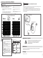
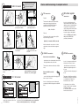
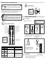
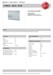
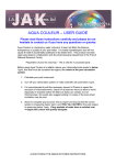
Network components to be installed
MDA MODULATED VENTILATION FOR OFFICES
fan
installation manual
acoustic duct
MR airflow regulator
Versions - composition of kits
MDA box
detector 2
230 V AC
12 V AC
slave
master valve
rigid or
extendible
duct
slave valve
ref. 110 17.115
- 1 MDA var. air volume box, 230 V AC
- 2 detectors
!
diffuser
General characteristics of the MDA box
The management card included in the box
analyzes the number of movements
perceived. A value called "modulo", which is
included between 1 and 10, is extracted from
this analysis every 10 minutes. The greater
the agitation, the higher the modulo value is.
At the beginning of each 10 minute period,
the box's shutter opens letting a 300 m3/h
flow rate pass through the airflow regulator.
The shutter closes after an opening time (in
minutes) equal to the modulo. The result of
this cyclical ventilation is a medium flow rate
included between 30 and 300 m3/h:
The modulo
is
- 1 MDA var. air volume box, 12 V AC
- 2 detectors
- 1 MDA var. air volume box
without detectors
connection
plenum
detector 1
operation:
The detectors produce an electric signal
by emitting a beep each time a movement
is detected.
ref. 110 17.108
ref. 110 17.116
The valve opens:
Then it closes::
The obtained medium flow rate is:
1
1 minute
9 minutes
30m3/h
2
2 minutes
8 minutes
60m3/h
3
3 minutes
7 minutes
90m3/h
4
4 minutes
6 minutes
120m3/h
5
5 minutes
5 minutes
150m3/h
6
6 minutes
4 minutes
180m3/h
7
7 minutes
3 minutes
210m3/h
8
8 minutes
2 minutes
240m3/h
9
9 minutes
1 minute
270m3/h
10
10 minutes
0 minute
300m3/h
- This product must be installed by a qualified technician.
- The manufacturer and the distributor refuse all responsibility if the case
any non conforming use of the product.
- In the case of any use that is not specifically indicated by the present
document, product protection could be jeopardized.
Installation and use characteristics
Brief product description:
Variable air volume box for regulating air flow rate blown
into or extracted from a service sector type room as a
function of the agitation measured by 2 movement
detectors.
Field of application:
Type of room:
Meeting rooms, offices, classrooms, changing-rooms
or any other service sector type room with variable
occupation (please consult us with regard to any other
applications).
In the new or in refurbishment.
Installation location:
Detectors: at false ceiling
MDA box: between false ceiling and ceiling.
Operating conditions:
Operating temperature: from + 5°C to + 40°C.
Operating relative humidity: maximum 80% RH at 31°C,
with linear decrease to 50% RH at 40°C.
Degree of pollution: 2
Devise entirely protected by double insulation.
Electrical characteristics
The ceiling diffuser is used in the 2 most interesting configurations for occupant comfort: nul flow rate or nominal
flow rate. In nominal flow rate, the air blown in, whose temperature can be different from that of the ambient air,
circulates at the ceiling, which ensures good distribution on the surface of the room and progressive dilution. This
prevents unpleasant feelings of falling cold air that typically appear in the case of low insufflation flow
rates.
110 17.115
110 17.116
supply voltage
230 V AC +/- 10%
12 V AC +/- 10%
frequency
50 Hz
50 Hz
power
10 VA
12 VA
maximum altitude
2000 m
application
use
in interior
Installation steps
An MDA kit (ref. 110 17.115 or ref.110 17.116) is installed by performing the following 3 steps:
AERECO - 9, allee du clos des charmes - Collegien 77615 Marne la Vallee cedex 3
France
8
TF3229
Product manufactured in France by:
- Determine the quantity and type of MDA kits needed
- Choose and dimension the components of the complete network
- Install the MDA kit components*
* The installation of network components not included in the MDA kits are not dealt with in this manual
1
Quantity, type and distribution of MDA kits
Before anything else, and to correctly understand how the different elements are to be arranged, visualize
the diagram on page 8
Determine the number of MDA kits and
detectors to be installed in the room.
The number and type of kits needed are determined by the
dimensions.
The positioning of the detectors must make it possible to:
Objective: To detect and to "sweep" the totality
of the room.
- sweep the room in limiting blind (unseen) zones so as to
ensure air quality
- limit the zones where 2 detectors are superposed (to prevent
them from being "counted two times").
The quantities, according to the dimensions of the
room, are determined by the two tables below:
This version does not include detectors and does not require any electric power supply of its own. It is
compulsory to associate with one of the two previous versions..
In the case of double flow, a complete MDA assembly and a slave box must be used. The only
function of the slave valve is to identically and simultaneously reproduce the opening and closing
movements of the master valve. It is not associated with any detector and does not need its own
electric power supply.
Graphs for determining the number of MDA
as a function of room dimensions
Number of MDA box kits as per room dimensions
18
17
3
16
5
13
14.0
14
4
12
11
6
8
2
5
6
8
8
6
2
3
4
4.1
4
3
1
2
2
3
8
12
16
20
3
6
9
12
15
2
4
6
8
10
1
2
3
4
5
10
8
7
master box
4
2
1
0
1
2
2.0
3
4
4.1
5
6
7
8
7.4
0
9 10 11 12 13 14 15 16 17 18
10.7
14.0 length
L in meters
1
2
2,0
3
4
5
6
4.1
7
8
9 10 11 12 13 14 15 16 17 18
7.4
10.7
14.0
length
L in meters
Signification of symbols
The following conditions must be met in
order for the system to operate correctly:
example (view from above):
This symbol placed on the connection hatch indicates an electric danger
linked to the presence of 230 V AC (in the 230 V AC version). It is
therefore indispensable to cut off the power supply before
dismounting the hatch!
7m
3.6 m
1.7 m
1.3 m
1.7 m
6m
- Installation of the MDA box in the
false ceiling.
- 2 detectors per MDA box (except in the
case of an odd number of detectors, last
detector alone for the valve)
- From 3 m to 3.6 m between 2 detectors.
- From 0.50 m to 2 m between a detector and the wall.
- Installation of detectors on the false
ceiling at approximately 2.50 m height.
- Symmetry of the detectors with
respect to the middle axes of the sides
of the room.
2
4
230 V AC or 12 V AC
power supply
11
3
2.0
1
!
25
2 wires
Maintenance
3.4 m
2.0
20
5
5
4.1
15
14
6
5
10
15
9
7.4
7
5
16
12
10.7
3
17
13
10
10
9
7.4
10
15
13
10.7
8
Number of detectors as per room dimensions
18
The valve can be accessed without dismounting the network thanks to the metal clamps that
maintain the lateral sleeves in place.
1.3 m
14.0
Detectors
width
I in meters
width
I in meters
MDA box kits
slave box
Stockage
detectors
From - 20°C to + 55°C.
TF3229
1
ref. 110 17.108 slave and double flow version
7
ref. 110 17.115
230 V AC version
!
Protection version 230 V AC:
Position a fuse [1A - 250 V]
on the power supply line.
Choice and dimensioning of complete network
2 fan characteristics
4 MR airflow regulator
characteristics
Pressure:
1 - Unscrew the connection hatch.
2 - Unclip the connection hatch by
pressing it in the middle.
The fan must be dimensioned so that with the
network pressure drops being taken into
consideration, the MR airflow regulator is
subjected to a pressure P, such that
3 - Insert the 230 V AC
power supply cord into it.
50 Pa < P < 250 Pa
Flow rate:
The fan must be able to supply a flow rate Q in
the pressure range, such that:
Its role is to set the flow rate at 300
m3/hour when the MDA shutter is open,
and when pressure is included between
50 and 250 Pa. The module used is
specific, dimensioned in coherence with
the MDA box. The module must be
inserted in a rigid or semi-rigid duct.
Choice of the MR300 module dia. 200
mm, provided by AERECO is
particularly recommended.
Q (m3/h) = 300 x number of MDA connected
4 - Unscrew the cord fixation.
5 - Slip and attach the cord
into its fixation.
6 - Slip on and attach the
cord lugs, then screw in order
to secure.
Note: the fan must be connected to a clock that
ensures that it is turned off and de-energized at
night.
3
air duct characteristics
5 diffuser characteristics
Between the fan and the MDA box:
12 V AC version
1 - Connect the 2 wires of the power
supply cord to terminals 1 and 2 of the
12 V AC MDA box.
This must have a minimum classification of M1(fire
class).
- Avoid bothersome cold air currents
- Optimize air quality throughout all of
the room
- Limit the noise linked to the passage of
the air
Between the MDA box and the
diffuser:
! VLSV
Its role is to soften the proper noise that may be
produced by the MR airflow regulator and the MDA
valve.
The square ceiling diffuser provided by
AERECO (see catalogue) is particularly
recommended for the quality of its
thermal and acoustic comfort.
It is important to choose a diffuser
having a "comfort flow rate" provided at
around 300 -350 m3/h.
A round diffuser with the same comfort
flow rate can also be used.
9 10 11 12 13 14 15 16
2 - Connect the free end of the cord to a Very Low Safety Voltage
transformer (VLSV) with double insulation, and then perform the
diverse connections (detectors, etc.) – refer to page 4.
TF3229
9 10 11 12 13 14 15 16
1 2 3 4 5 6 7 8
LED
LED
1 2 3 4 5 6 7 8
Its role is to homogeneously diffuse the
air blown into the room, in order to:
- acoustic shaft (indispensable) with length greater
than or equal to 1.5 meters.
12 V AC
6
9 - Screw on the hatch, and then
perform the diverse connections
(detectors, etc.) – refer to page 4.
230 V AC
ref. 110 17.116
8 - Clip the connection hatch back
on.
12 V AC
7 - Secure the cord in its
fixation.
- rigid stainless steel or aluminum duct, dia. 200 mm
- semi-rigid aluminum duct, dia. 200 mm.
3
Requirements relative to wiring and power supply
Note
A clearly indicated and accessible cut off system must be positioned
near the valve. Each valve must be connected to the clock of the room
ventilation system so that it is turned off and de-energized at least during
the night.
detector connections:
i
Detector LED
The LED visible under the lens
lights up each time that a
movement is detected.
Identify and mark, and make the connections on the terminal boxes of the variable air volume
box and the detectors as a function of the connections of the chosen version:
P
IM
!
Any incorrect connection can lead to destruction of the management card and/or
the detectors.
All of the wires used for the wiring, including the power supply of the 12 V AC and
230 V AC versions must be normalized and have a section of from 0.75 mm2 to
1.5 mm2.
Installation of MDA kit components
7
Installing the
detectors
Respect the locations determined in
step 1.
8 to 18 mm
1 2 3 4 5 6 7 8
9 10 11 12 13 14 15 16
LED
12V AC power supply (for MDA 12V AC)
12V AC power supply (for MDA 12V AC)
6 V 100 mA max. box state relay
6 V 100 mA max. box state relay
6 V 100 mA max. presence state relay
6 V 100 mA max. presence state relay
slave box terminal 7
slave box terminal 8
dia. 62 to
dia. 70 mm
ABC
Push the detector into the
Check that the
When the hole has been drilled, pass the 2
false
ceiling
by
"screwing"
detector is correctly
power supply wires and the signal wire through
it in. Be careful to not push in place.
it, and connect them to the detector.
the lens all the way into the
false ceiling lentille.
i
LED
The box LED makes it possible to
check that the MDA is turned on
and energized: the power supply
must be verified if the LED is not
lit.
!
230 V AC power supply (for MDA 230 V AC)
230 V AC power supply (for MDA 230 V AC)
+ presence relay
6
- presence relay
9
Forced opening
10
Forced opening
Output voltage 6 V DC, 100 mA minimum
Input to be short-circuited by a switch.
Relay activated when a movement is detected.
The action is maintained for 5 to 6 min after
the last detection.
The shutter opens when terminals 9 and 10 are
short-circuited. The shutter / box returns to
automatic operation when the circuit is opened.
8
Installing the
LED
1 2 3 4 5 6 7 8
4
5
Never connect 2 detectors on the
same terminals. This will irreversibly
deteriorate the electric components.
Action
Relay activated when the shutter is open.
Prohibited
9 10 11 12 13 14 15 16
!
Detector connection:
MDA terminal Description
Characteristics
3
+ valve state relay Output voltage 6 V DC, 100 mA minimum
4
- valve state relay
The diffuser must be located in an
area near to the 2 associated
detectors.
signal
"master" MDA box connections:
switch forced opening
switch forced opening
detector 1 - terminal A:
detector 1 - terminal B: signal
detector 1 - terminal C:
detector 2 - terminal A:
detector 2 - terminal B: signal
detector 2 - terminal C:
signal
MDA box
Positioning the MDA valve:
To prevent any acoustic discomfort, the box should be installed as far as possible from
the diffuser, or even, if possible, outside of the room.
(shutter bearing noise: approximately 31 dB(A)).
TF3229
T
AN
T
OR
ABC
6
5