1
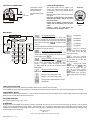
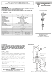
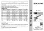
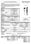
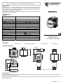
Thank you for choosing a NIVELCO instrument.
We are sure that you will be satisfied throughout its use.
PLK-501, PLK-501-Ex
UNIVERSAL PLUG IN DISPLAY
1. APPLIACTION
UNICONT PLK-501 is a universally applicable plug-in process display. It is available in explosion proof,
intrinsically safe version, too. The display is designed for 4…20 mA transmitter loop connection without the
need of external power supply. The displayed numerical values can be freely scaled to the current input by
the user, setting the maximum and the minimum value.
The display unit is for standard two wire transmitter, DIN 43650 connection. It should be assembled between
the sensor base and the connector socket.
USER’S MANUAL
2. TECHNICAL DATA
2.1 GENERAL
Type
UNICONT PLK-501, PLK-501 Ex
System connection
Input
Display
Set up range
Damping time
Display accuracy
2 wire DC
4 … 20 mA (current loop)
4 digit, 7,62 mm LED
- 1999 … + 9999
0,3 … 30 sec
0,1% ± 1 digit
≤ 6 V [IIN: 25mA]
0°C … + 70 °C
+ 25 °C
120 … 150 VDC (max 1 sec at 25 °C)
Class III.
Voltage drop
Ambient temperature
Reference temperature
Over voltage
Electrical protection
Explosion protection
II (1) 2 G EExia IICT4
ATEX
Umax < 28V
Pmax < 660 mW
Imax < 93 mA
DIN 43650 connector
IP 65
47 x 47 x 68 mm
~ 100 gr
Intrinsic safety
Electric connection
Ingress protection
Dimensions
Weight
Manufacturer:
NIVELCO Process Electronics Co.
1043 Budapest, Dugonics u. 11.
Phone: 36-1 369-7575 ♦ Fax: 36-1 369-8585
e-mail: [email protected] www.nivelco.com
2.2 ACCESSORIES
– User’s manual
– Warranty sheet
– Stick-on measure unit label set
– Stick-on face plate
– Assembly screw
3 TECHNICAL DRAWINGS
47
bar
36
DIN 43650
bar
50
47
120°
210°
–2
3
19,5
44,5
68
+1
Ø 46
Plug on display with pressure transmitter
4. INSTALLATION
Plug the display unit between the sensor’s connector (standard DIN 43650) and the socket with the wires connected, than fix the three parts with the assembly screw.
Pay attention for the sealing between the parts!
Choose the right measuring unit label from the set and stick it on in the appropriate location than stick on the faceplate positioning carefully, so that the buttons can be
used with the faceplate, too.
plk5012a0600h_01.doc ♦ 1 / 2
5. ELECTRICAL CONNECTIONS
2
–
–2
3
+1
4-20 mA
6. SETTING UP THE DISPLAY
Connect the 2 conductor
cable to the DIN socket
after disassembling it.
UT
[24 V DC]
1
+
Lead the cable through the
gland.
The displayed values must be adjusted to the
4-20mA loop current that flows through the unit
(scaling process). This is done via the two buttons on
the faceplate.
UNICONT PLK-501 display offers numerous set-up
menu points.
Entering the configuration menu and navigating
among the menu points is done by the up and
down arrow buttons.
Pressing the two buttons simultaneously does
entering and returning/saving from the menu
points.
Pressing a button for longer period than
5 seconds the rate of counting increases.
FACEPLATE
bar
DOWN
UP
Programming
buttons
MENU GRAPH
Security code OFF (default)
“1” appears after entering the menu point if security code
option is off. Changing this digit to the previously determined
security code disables further programming. After exiting the
menu point the display shows:
. The default security
code is “0”.
Pressing the two buttons simultaneously enters the menu point
and performs save-and-exit command.
Not applicable
Not applicable
Not applicable
Not applicable
Not applicable
Read out of maximum
measured value since the last power
Security code ON, programming disabled
up. The values can be reset with
Entering the menu point „1” appears. Entering the valid
interrupting the power.
security code will enable programming. After exiting the menu
point the display shows:
Read out of minimum
measured value since the last power
Setting the security code: enter menu point and
up. The values can be reset with
set “835” numerical value (special functon)
appears
interrupting the power.
on the display. Acknowledge with simultaneous button
pressing – “1” appears – enables new security code entry
Loading factory default
(0….9999). Accept the new code with the buttons pressing settings. Enter the
menu
them together.
point, enter the number “729” and
press the two buttons together.
Setting the decimal point position:
appears and pressing the
Enter - set the position – save/exit
buttons together loads the factory
default settings except for the security
Setting the value corresponding to 4mA
code.
Setting the value corresponding to 20mA
Input signal filter, adjustable between 0,3-30sec
Not applicable
7. EXPLOSION PROTECTION
Only explosion proof transducer and explosion proof display is allowed to use in explosion proof environment!
In such conditions the unit must be fed by intrinsically safe galvanically separated power supply or connected to 4...20mA current loop through galvanical separator.
8. MAINTENANCE, REPAIR
The device does not require routine maintenance. In case dust adheres to the face of the device the faceplate can be cleaned. Repairs during or beyond the warranty
period are carried out solely by the manufacturer in the factory.
9. STORING CONDITIONS
Environmental temperature range: –25°C...+80°C
10. WARRANTY
All Nivelco products are warranted free of defects in materials or workmanship for a period of two years from the date of purchase. The warranty is valid only with the
warranty card and the purchase invoice together. Repairs - under guarantee or not - are carried out at the Manufacturer's premises.The Purchaser is liable for costs of
dismantling and re-installation as well as transport costs. Nivelco shall not be liable for misapplication, labour claims, direct or consequential damage or expense arising
from the installation or use of equipment.
plk5012a0600h_01.doc
2009. July 14.
Nivelco reserves the right to change technical specifications without notice.
plk5012a0600h_01.doc ♦ 2 / 2