1
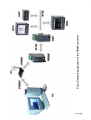
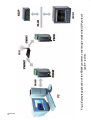
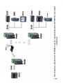
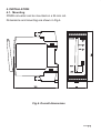
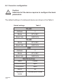
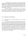
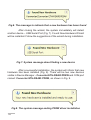
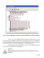
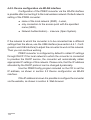
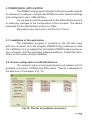
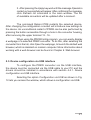
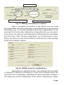
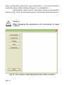
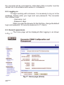
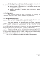
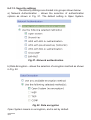
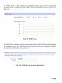
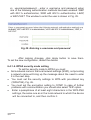
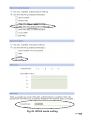
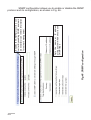
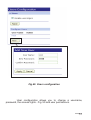
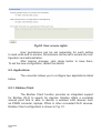
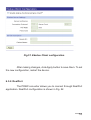
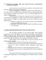
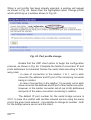
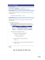
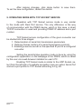
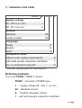
RS-485/ETHERNET WI-FI
CONVERTER
PD8W TYPE
USER’S MANUAL
1
2
Contents
1. APPLICATION...................................................................................................5
2. CONVERTER SET ..........................................................................................10
3. BASIC REQUIREMENTS, OPERATIONAL SAFETY ....................................10
4. INSTALLATION ...............................................................................................11
4.1. Mounting ..............................................................................................11
4.2. PD8W electrical connections .............................................................12
4.3. Transmission parameters of the serial interface .............................13
4.4. Converter configuration ....................................................................14
4.4.1. Configuration via USB interface .....................................................15
4.4.2. Device configuration via WLAN interface ......................................18
5. PD8WCONFIG APPLICATION .......................................................................19
5.1. Installation of the application ............................................................19
5.2. Device configuration via WLAN interface .........................................19
5.3. Device configuration via USB interface ............................................21
6. WEB BROWSER ............................................................................................25
6.1. Getting started with a web browser ..................................................25
6.2. Logging on ...........................................................................................26
6.3. General appearance ...................................................................................26
6.4. Configuration .............................................................................................27
6.4.1. Network configuration .....................................................................27
6.4.1.1. IP Settings (WiFi Settings)............................................................28
6.4.1.2. Local network settings .................................................................29
6.4.1.3. Security settings ...........................................................................30
6.4.1.4. WPA2 security mode setting ........................................................32
6.4.1.5. Setting authentication ..................................................................34
6.4.1.6. Network services settings ............................................................36
6.4.1.7. IP for forwarding settings .............................................................37
6.4.1.8. Tunnel setting ................................................................................38
6.4.1.9. Advanced network settings..........................................................39
6.4.2. Serial port settings ...........................................................................40
6.4.3. I/O configuration (GPIO) ..................................................................42
6.4.4. Alarms configuration .......................................................................43
3
6.4.5. System configuration ......................................................................46
6.4.6. iDigi configuration ...........................................................................49
6.4.7. Users .................................................................................................50
6.5. Applications .........................................................................................52
6.5.1. Ekahau client ....................................................................................52
6.5.2. RealPort ............................................................................................53
6.6. Management ........................................................................................55
6.6.1. Serial Port Management ..................................................................55
6.6.2. Connection Management ................................................................56
6.7. Administration .....................................................................................56
6.7.1. File Management ..............................................................................56
6.7.2. Configuration Back-up/Restoring Configuration ..........................57
6.7.3. Software Update ...............................................................................58
6.7.4. Restoring default parameters .........................................................59
6.7.5. Device Information ...........................................................................59
6.7.6. Rebooting .........................................................................................59
6.8. Logging a user out ..............................................................................60
7. OPERATING MODE WITH REALPORT SERVICE ........................................60
7.1. RealPort service driver file information ............................................61
7.2. Example of driver installation in Windows XP .................................61
7.3. RealPort driver configuration in Windows XP ..................................62
7.4. Example of Lumel Heat and Lumel Process configuration
to work with PD8W .............................................................................64
8. SERIAL BRIDGE MODE WITH THE UDP PROTOCOL ................................64
8.1. Setting serial port transmission parameters ...................................64
8.2. Configuration of client service operation .........................................64
9. OPERATING MODE WITH TCP SOCKET SERVICE.....................................68
10. TECHNICAL DATA .......................................................................................71
11. ORDERING CODE PD8W.............................................................................73
12. MAINTENANCE AND SERVICE...................................................................74
4
1. APPLICATION
RS-485/Ethernet Wi-Fi converter PD8W type allows master
devices to transmit data via a wireless Ethernet Wi-Fi network to the
devices with RS-232 and RS-485 interface.
The converter has three operating modes: RealPort network
service, serial bridge service with the UDP protocol, TCP Socket service.
In the first and third mode, the switching master device of the system
is a PC using Ethernet Wi-Fi interface. In the second mode, the converter
works with a device with Master function and RS-232 and RS-485 serial
interfaces.
The converter PD8W to work with RealPort network service
requires the installation of a virtual serial port driver on a PC with Microsoft
Windows. Thanks to the PD8W type converters, this driver provides the
existing master systems, i.e. programs like Lumel Heat and Lumel Energy, the ability to transmit data between devices with RS-485 or RS-232
interface using Ethernet Wi-Fi network (Fig. 1). When used in this way,
the converter allows to work with one master computer in the given time.
When using PD8W to support Modbus and Lumbus industrial protocols
- its correct interaction with master systems installed on a PC depends
on the built-in mechanisms to control time intervals between the received
transmission characters.
Using PD8W in the second mode, the RS-485 bus can be
expanded with successive segments using additional PD8W converters and Ethernet Wi-Fi local network. Properly configured, one pair of
converters allows to build a system working in the serial bridge mode
(Fig. 2). It is also possible to configure their operation in „one-to-several”
mode (as a set including up to 65 converters – Fig. 3). Function 2 of
the converter operates in the Ethernet Wi-Fi local network with UDP
datagram protocol support.
5
Function 3 operation is very similar to the converter working with
RealPort network service except that it is not required to install software
virtual serial port driver on a PC with Windows. Communication between
a PC and PD8W converter is via TCP Socket mechanism. In this case,
in order to connect to the device, it is necessary to specify an IP address
of the converter and a port number (Fig. 1).
6
7
Fig.1. Example application of the PD8W converter
8
Fig.2. Example application of the PD8W converter, serial bridge mode with UDP protocol
(point – point).
9
Fig.3. Example application of the PD8W converter, serial bridge mode with UDP protocol (point
– multipoint).
2. CONVERTER SET
Complete set of the converter includes:
- PD8W converter
- PD8W user’s manual
- Warranty card
- CD with software
1 pc,
1 pc,
1 pc,
1 pc.
3. BASIC REQUIREMENTS, OPERATIONAL SAFETY
Symbols located in this manual mean:
Especially important, please read before connecting the
converter. Non-compliance with the comments marked by
this symbol could result in damage to the converter.
Should pay attention, if the converter is not working as
expected.
Caution:
Removal of the converter housing during the warranty period voids
the warranty.
Comments concerning safety:
Assembly and installation of the electrical connections should
l
conducted only by people authorised to perform assembly
of electric devices.
l
Always check the state of connections before turning
the converter on.
Prior to taking the converter housing off, always turn the supply
l
off and disconnect measuring circuits.
The device is designed to installation and usage in the industrial
l
electromagnetic environment.
A switch or a circuit-breaker should be installed in the building
l
or facility. It should be located near the device, easily accessible
by the operator, and suitably marked.
10
4. INSTALLATION
4.1. Mounting
PD8W converter can be mounted on a 35 mm rail.
Dimensions and mounting are shown in Fig.4.
Fig.4. Overall dimensions
11
4.2 PD8W electrical connections
The supply and external signals must be connected acc. to Fig. 5
and the Table 1 in which the assignment of the particular lead-outs have
been described.
OR 20...50 V A.C./D.C.
Green LED indicates
the correct supply
- diode PWR
PD8W
Red LED RxD signals
data reception through
RS-485
Yellow LED TxD signals
data transmission
through RS-485
mini USB
WLAN
Fig.5. PD8W converter electrical
connections
12
Terminal
SUPPLY DEPENDING ON THE VERSION CODE (80...253 V A.C./D.C.
Description of the leads-out
Table 1
Terminal description
5
GND line
6
Line B
(RS-485 interface)
7
Line A
(RS-485 interface)
8
Line 5 V d.c.
9
Line + supply
10
Line - supply
11
not used
12
TxD output
(RS-232 interface)
13
RxD input
(RS-232 interface)
14
GND line
15
CTS line
(RS-232 interface)
16
RTS line
(RS-232 interface)
Caution:
In order to obtain full immunity of the converter against electromagnetic
noise in an environment, it is recommended to observe the following
principles:
l do not supply the converter from the network in the proximity
of devices generating high pulse noises (inverters) and do not
apply common earthing circuits,
l apply network filters,
l all shields should be one-side earthed or connected to the
protection wire, the nearest possible to the converter,
l as a rule of thumb, wires transmitting different signals should
be spaced as far as it is possible (at least 30 cm) and should
be crossed only at the right angle of 90o.
4.3 Transmission parameters of the serial interface
The PD8W converter works with industrial devices from
the RS-485 side at following baud rates: 300 bit/s, 600 bit/s, 1200 bit/s,
2400 bit/s, 4800 bit/s, 9600 bit/s, 19200 bit/s, 38400 bit/s, 56000 bit/s,
115200 bit/s.The maximum serial baud rates depend on the length
of transmission lines and are presented in the Table 2. A terminator should
be used at the length of the line over 800 m (a resistor 120 Ohm), which
connects the terminals „A” and „B” of the PD8W converter.
Dependence of the maximum baud rate from the line length
Table 2
Length of the
transmission line
Maximum baud
rate
Comments
100 m
115200 bit/s
without terminator
200 m
56000 bit/s
without terminator
800 m
38400 bit/s
with a terminator for the
baud rate > 9600 bit/s
1200 m
9600 bit/s
with a terminator
13
4.4 Converter configuration
Caution:
Initial start of the device requires to configure the basic
parameters.
The default settings of a delivered device are shown in the Table 3.
Default settings
Table 3
RS-485
Address
1
Mode
RTU 8N1
Baud rate
9600 bit/s
RS-485
Mode
RTU 8N1
Baud rate
9600 bit/s
USB
Address
1
Mode
RTU 8N1
Baud rate
9600 bit/s
WLAN interface
14
SSID
Lumel
Authentication
open
Encryption
open
DHCP
on
Operation
mode
Access point mode
The PD8W converter requires to configure the settings
appropriate for IP network protocol and Wi-Fi local area network at the
initial start. The settings that must be configured are: IP address of the
PD8W converter, subnet mask, address of the default gateway, the name
of the local network (SSID) and security settings of the local network. This
data should be obtained from the administrator of the computer network
which PD8W is connected to.
When the converter is connected to the local area network
with DHCP service available, IP settings of PD8W will be configured
automatically. Configuration of settings to allow the converter connecting
to a wireless local area network is possible via the USB interface.
4.4.1. Configuration via USB interface
The converter is configured by default to communicate
through a USB port.
To configure the device via a USB interface it should be connected to the PC with a mini-USB cable. After connecting the converter,
the operating system will inform that a new device is found with a message
shown in Fig. 6. Found New Hardware Wizard of the Universal Serial
Bus will be started automatically. Follow the suggestions of the wizard
by selecting the installation from a specific location and providing a path
to the drivers included on the supplied CD. Drivers are compatible with
the following systems: Windows 2000, XP, Server 2003, Vista, Windows 7,
Server 2008 (x86 and x64). When installing the drivers, you may receive
information about missing digital signature for drivers. Please ignore
it and continue with the installation.
15
Fig.6. The message to indicate that a new hardware has been found
After closing the wizard, the system immediately will detect
another device – USB Serial Port (Fig. 7). Found New Hardware Wizard
will be restarted. Follow the suggestions of the wizard during installation.
Fig.7. System message about finding a new device
After a successful installation, the system will inform that new
hardware has been installed (Fig. 8). There will be two new devices
visible in Device Manager – Converter ETH-RS485 PD8W and COM port
named: Converter ETH-RS485 PD8W, as shown in Fig. 9.
Fig.8. The system message ending PD8W driver installation
16
Fig.9. Device Manager window with the PD8W converter installed
Then run the PD8WConfig program delivered on CD
and follow the installation instructions provided in point 5.1. Installation
of the application and instructions for configuration via USB interface
provided in point 5.3 Device configuration via USB interface.
After entering the configuration, save it and restart the device
for the new configuration to take effect.
Caution:
After changing the parameters it is necessary to reset
a device.
17
4.4.2. Device configuration via WLAN interface
Configuration of the PD8W converter via the WLAN interface
is possible after connecting it to the local wireless network. Default network
setting of the PD8W converter:
l
name of the local network (SSID) - Lumel,
l
only connection to the access point with the specified
name (SSID),
l
Network Authentication) - insecure (Open System).
If the network to which the converter is to be connected has a different
settings than the above, use the USB interface (see section 4.4.1. Configuration via USB interface) to adjust the converter to work in this network.
Then you can continue working.
PD8W converter is configured by default to obtain IP settings
through DHCP. If the local network to which the converter is connected
to provides the DHCP service, the converter will automatically obtain
appropriate IP settings of this network. Please note, that the IP address
allocated by the DHCP protocol can be changed dynamically.
Use the PD8WConfig program included on the CD to set the
IP address, as shown in section 5.2 Device configuration via WLAN
interface.
If the IP address is known it is possible to configure the converter
via the website, as shown in section 6. Web browser.
18
5. PD8WCONFIG APPLICATION
The PD8WConfig program included in the set is used to search
for devices on a network, configure the PD8W converter network settings
and configuration via a USB interface.
It is required to enter the password for the administrator account
to make any changes to the configuration of the converter. The default
password for the administrator account is: dbps
More about user accounts in section 6.4.7 Users.
5.1. Installation of the application
The installation program is included on the CD that came
with the converter. Run the program PD8WConfig_install.exe to start
the installation. It is an application that installs PD8WConfig program on
your computer, and the necessary software additions. Follow the instructions on the screen during installation.
5.2. Device configuration via WLAN interface
The program scans a local area network and creates a list of
available converters of PD8W and PD8 series. This list is displayed in
the field List of Converters (Fig. 10).
Fig.10. The list of available converters
19
The current IP address of the converter is shown in the field IP Address.
If you can see that the converter has a wrong IP address such as 0.0.0.0,
this means that the network has no DHCP service available. In such case,
you must configure PD8W with wrong address manually as follows:
1. After selecting the converter, click Configure IP settings.
2. In the window Set IP Address fill in the data obtained from
the network administrator (Fig. 11). As the password, enter
the password for the administrator account which by default
is set to: dbps
Fig.11. Configuration of network settings
20
3. After pressing the Apply key wait until the message Operation
carried out successfully will appear. After confirming the message,
click Refresh list command in the main window. The list
of available converters will be updated after a moment.
The command Reboot PD8 restarts the selected device.
After changing the configuration a restart will introduce new settings to
the device. An unconditional restart of PD8W can be also performed by
pressing the button accessible through a hole in the converter housing,
after removing the upper terminal 13 - 16.
When using the PD8WConfig program, you can easily display
a webpage of a selected PD8W converter. To do this, after selecting the
converter from the list, click Open the webpage, to launch the default web
browser, which is standard on modern computer. More information about
working with a web browser can be found in Chapter 6. Web browser.
5.3. Device configuration via USB interface
To configure the PD8W converter via the USB interface,
the device must be connected via the USB cable to your PC and the
drivers should be installed in accordance with section 4.4.1. Device
configuration via USB interface.
Selecting the option Configuration via USB as shown in Fig.
12 lets you access the window, which allows a configuration via USB.
21
Fig.12. Selecting the option Configuration via USB
The first step is to connect to the device, as shown in Fig. 13.
To make a connection you must:
l
choose a device from the list (a list of all converters currently connected
via the USB interface);
l
select transmission parameters, the default values are: baud rate
9600 bit/s and 8N2 mode;
l
enter the login and password for the administrator account, the default
login is root and the password dbps;
l
click an option Connect.
Once connected to a device you will get a message about
the connection status and error messages if any.
22
Available devices
Transmission parameters
User login and password
Fig.13. Making connection to a device
After a successful connection to the device, you can read
the configuration, save the configuration, reboot the device or check device
information, Fig. 14. It is also possible to save the configuration to a file
and read it from a file. After reading the configuration file, you can save it
to the device. An option to read and write a configuration file is available
from the menu Files. During configuration, you should keep in mind,
that for the device to work in the network it must have the same settings
as the local wireless network.
Fig.14. PD8W converter configuration
Depending on selected options, the windows will be edited
or blocked to allow the introduction of only those settings which are
required for the configuration. Selecting the option Download configuration reads the current configuration of the device. Selecting the option
23
Save configuration saves the new configuration. It is recommended to
restart the device after making changes in a configuration.
Selecting the option Device information brings up the window
shown in Fig. 15 for checking the specific information about the device.
Caution:
After changing the parameters it is necessary to reset
a device.
Fig.15. The window with information about the converter
24
To set the security mode to WPA2 proceed in accordance with
section 6.4.1.4. WPA2 security mode setting, except that the configuration
should be done via USB interface (Fig. 16).
Fig.16. WPA2 security mode setting
6. WEB BROWSER
PD8W converter allows you to configure and manage it via
the website.
6.1. Getting started with a web browser
Access to the server can be achieved by entering the IP address
of the converter in the web browser, for example: http://192.168.1.1 (where
192.168.1.1 is an example of address of the converter). You can also use
the PD8WConfig application to run a web browser as presented in section
5.2. Device configuration via WLAN interface.
The PD8W converter requires to configure the necessary IP
protocol settings at the initial start that is:
- IP address,
- subnet mask,
- address of the default gateway.
These data should be obtained from the administrator of the network which
25
the converter will be connected to. Initial start of the converter must be
carried out in accordance with section 4. Installation.
6.2. Logging on
To begin working with a browser, it is necessary to log on to the
webpage. Please enter your login and user password. The converter
has a default user:
- Username: root
- Password: dbps
When you open the browser for the first time, change the default
login and password for security reasons (6.4.7. Users).
6.3. General appearance
The home page will be displayed after logging in as shown
in Fig. 17.
Fig.17. Home page (Home)
26
On the Fig. 17 you will notice that the navigation menu is on
the left hand side. The home page includes the following:
a) Getting Started - includes a link to the tutorial to help you
navigate the webpage,
b) System Summary - includes basic information about
the device.
6.4. Configuration
The converter allows a user to configure the settings of
a network, serial port, GPIO, alarms, system, iDigi and users.
6.4.1. Network configuration
The network settings in the converter can be done in two
different ways. You can use the static or dynamic settings.
For static settings, all settings must be entered manually
and they will be assigned on a permanent basis. To enter the correct
values, please contact the administrator of the network which
the converter will be connected to. Once set, the static settings will not
change and the device can always be found by its IP address.
Dynamic settings will be automatically assigned by DHCP
protocol. In this case, the IP address may change, so the connection with
the configuration webpage can be broken. Please use the PD8WConfig
application to search again for the device in such case.
The Fig. 18 shows a structure of the network configuration.
27
Fig.18. Network configuration
6.4.1.1. IP settings (WiFi IP Settings)
IP settings are shown in Fig. 19
Fig. 19: Configuration of IP settings
28
Fig. 19 shows the following options to choose from:
- Obtain an IP address automatically using DHCP - means
setting the IP address automatically through DHCP. After
restarting the device it is necessary to search again for the
device using the PD8WConfig application.
- Use the following IP address - sets the configuration
selected manually by the user. To enter the correct values,
please contact the administrator of the network which
the converter will be connected to.
- Enable AutoIP address assignment - selecting this option will
automatically configure the IP address if the address is not
available in any other way. For example when the address is
set via DHCP and no DHCP server is
available.
Click Apply button to save the changes and the device will
use the new settings after reboot.
6.4.1.2. Local network settings
The Fig. 20 shows the settings for the local network.
Fig.20. Local network settings
Click Apply button to save the changes and the device will use the new
settings after reboot.
29
6.4.1.3. Security settings
The security settings are divided into groups shown below:
a) Network Authentication - allows the selection of authentication
options as shown in Fig. 21. The default setting is Open System.
Fig.21. Network authentication
b) Data Encryption - allows the selection of encryption method as shown
in Fig. 22.
Fig.22. Data encryption
Open System means no encryption, and is set by default.
30
c) WEP Keys - this feature is enabled when you select a method
of encryption. It allows to use WEP keys and selecting one of the four,
Fig. 23.
Fig.23. WEP keys
d) WPA PSK - allows to enter a password when WPA PSK authentication
is selected, Fig. 24. Whenever the network name is changed (SSID)
the password must be re-entered.
Fig. 24: Setting an access password
31
e) username/password - enter a username and password when
one of the following authentication methods has been enabled: WEP
with 802.1x authentication, WPA with 802.1x authentication, LEAP,
or EAP-FAST. The window to enter the user is shown in Fig. 25.
Fig.25. Entering a username and password
After making changes, click Apply button to save them.
To set the new configuration, restart the device.
6.4.1.4. WPA2 security mode setting
To set the security mode to WPA2 you must:
l Set a network name in the local network settings (SSID), not providing
a network name will bring up the message about the need to enter
it in the next step.
l
You must set the security settings to WPA with pre-shared key
(WPA-PSK), Fig. 26.
l
You must set the encryption setting to CCMP. In case of further
problems with communication you should also select TKIP option.
l
Enter a passphrase of at least eight characters in the WPA PSK
settings, the same one as in the local network to which the device
will be connected to, and then confirm it.
32
Fig.26. WPA2 mode setting
33
After making changes, click Apply button to save them.
To set the new configuration, restart the device.
6.4.1.5. Security settings
Authentication setting for the network authentication is only
possible if the selected security settings are WEP with 802.1x authentication or WPA with 802.1x authentication. The security settings are
divided into groups shown below:
a) EAP Methods - allows to select an authentication method,
as shown in Fig. 27.
Fig.27. EAP methods
b) PEAP/TTLS Tunnelled Authentication Protocol - allows to select
a tunneling protocol if you select PEAP or TTLS authentication
methods as shown in Fig. 28
Fig.28. Selecting a tunneling
protocol
34
c) Client Certificate - allows to upload files with certificate and
private key, this option is available after the TLS authentication
method is enabled, Fig. 29.
Fig.29. Client certificate
If a key file is required enter a password and then confirm it.
d) Trusted Certificates - allows to set a trusted key, upload and check it
as shown in Fig. 30.
Fig.30. Trusted Certificate
e) Installed Certificates - allows to check what certificates are
installed and to delete the selected certificates, as shown in Fig. 31.
Fig.31. Installed certificates
35
After making changes, click Apply button to save them.
To set the new configuration, restart the device.
Fig. 32. Network services settings
6.4.1.6. Network services settings
Network services settings are shown in Fig. 32, allow to enable or disable certain network services and configure a TCP/IP port which
the services will use for listening.
36
Please note, that the standard ports are set which are used in
most applications.
After making changes, click Apply button to save them.
To set the new configuration, restart the device.
6.4.1.7. IP Forwarding Settings
IP Forwarding Settings are used to manage IP forwarding
between network interfaces. Static routes can be defined and stored in
the routing table.
You can enable or disable IP forwarding by checking
or unchecking the box Enable IP Routing, as shown in Fig. 33.
Fig.33. IP forwarding settings
IP forwarding allows to receive packets from one network interface and transferring them to another one. Using the static routes
allows routing IP datagrams to a network that is not in the local network
nor is accessible via the default route (gateway). You can configure up
to 16 static routes. The value 255.255.255.255 is not allowed in the gateway address field. This value will be ignored for WAN, WiMAX and
PPP. Static route configuration may be rejected by the network stack if
no gateway has been assigned.
Assigned gateway is used as a static routes gateway if the
static routes gateway is configured as 0.0.0.0 for the LAN interface (as
shown in Fig. 33).
After making changes, click Apply button to save them. To set
the new configuration, restart the device.
37
6.4.1.8. Tunnel setting
Tunnel settings are shown in Fig. 34. Tunneling is used to
connect two network devices, one on the local network via the converter
and the other on the remote network. The device can be configured to
initiate tunneling.
Tunneling is initiated when the device opens a TCP socket of
the converter on the configured port. The converter opens a separate
connection to a specific host. When the tunnel is set, the converter acts
as a proxy server for data between the network socket and the local
network socket, regardless of which device initiated the socket.
After making changes, click Apply button to save them. To set
the new configuration, restart the device.
Fig. 34: Tunnel setting
38
The time in seconds between
each keepalive message.
Fig. 35. Advanced network settings
The period of idle time before a
keepalive message is sent.
Number of attempts to send an
keepalive packets.
The primary server is
checked first for each
type of server. If none
of the servers can not
be contacted, the next
server type in the list is
checked. Select an item
and press up or down
button to change the
priority order.
Static DNS servers are
specified
independently
of the network interface
and connection status.
Address 0.0.0.0 means
that no server is specified.
Optional, only if DHCP
protocol is set.
6.4.1.9. Advanced network settings
Advanced settings allow to fine-tuning the network connection
and the network interfaces as shown in Fig. 35.
After making changes, click Apply button to save them.
To set the new configuration, restart the device.
39
6.4.2. Serial port settings
PD8W converter allows to configure the serial port settings.
The Fig. 36 shows how to access the serial port configuration.
First, there is a window with a list of ports; selecting a particular
port brings up a window where it is possible to select a port profile.
The default profile is access through the terminal - Local Configuration.
Fig.36. Serial port settings
40
Selecting a port profile brings up a window shown in Fig. 37
allowing further configuration.
Fig.37. Port profile settings
Appearance of the window shown in Fig. 37 and the windows
with the basic settings (Fig. 38) and the advanced settings (Fig. 39)
of a serial port depends on a port profile that has been selected in accordance with Fig. 36.
Fig.38. Serial port basic settings
41
Fig.39. Serial port advanced settings
After making changes, click Apply button to save them.
To set the new configuration, restart the device.
6.4.3. I/O configuration (GPIO)
Converter built-in Wi-Fi module allows to configure five of its
free pins. Pin configuration is possible, but not recommended due to the
stability of the converter.
Configuration of the universal I/O is shown in Fig. 40 allows
to configure the 5 pin for standard serial communication as well as for
user-defined communication. You can set one of the following options
for each pin:
- Serial - serial communication is set as the default. Each pin is
assigned to another signal listed in parentheses (DCD, CTS, DSR,
RTS, DTR).
- In - user-defined input from a device connected to the converter.
You can set to send an e-mail with information about input status
using the alarm configuration (see the alarm configuration).
42
- Out - user-defined output from the converter to the connected
device.
Fig.40. I/O settings
After making changes, click Apply button to save them.
To set the new configuration, restart the device.
6.4.4. Alarms configuration
The PD8W converter can be configured to generate an alarm
based on the occurrence of a specific event. A device sends an e-mail
when an alarm is detected. Configure alarm notification settings for a
device to send a message, Fig. 41.
43
Fig.41. Alarm notification settings
Alarm conditions tab shows a list of all alarms as shown
in Fig. 42. It allows to enable or disable the alarm; click the alarm to bring
up a window to configure a selected alarm (Fig. 43).
Fig.42. Alarm conditions
44
Fig.43. Alarm configuration
After making changes, click Apply button to save them.
To set the new configuration, restart the device.
45
6.4.5. System configuration
System configuration allows you to configure device identification, date and time as well as SNMP settings.
Configuration of device identification is shown in Fig. 44.
You can set the device description, a contact person - usually
a network administrator, the location of the device and the device ID that
corresponds to the ID used by the iDigi server.
Fig.44. Device identification
Date and time configuration sets the date and time of the
device or sets the UTC offset for the device time system (Fig. 45).
46
Specifies the UTC offset for this
device. This value can be used to
modify the date and time to compensate for time zone and daylight
saving time.
Configures
the
access to five external sources of time
which can be used
to set and maintain the time for the
device.
Type the time sources
Sample ranking The smaller
the number, the greater trust.
Fig.45. Date and time configuration in the concentrator
47
48
Fig.46. SNMP configuration
Sets the name or IP address
of the system which should send
SNMP traps.
Enables the SNMP protocol in a converter. By enabling SNMP, a network
administrator can retrieve information
for network management.
SNMP configuration allows you to enable or disable the SNMP
protocol and its configuration, as shown in Fig. 46.
After making changes, click Apply button to save them.
To set the new configuration, restart the device.
6.4.6. iDigi configuration
IDigi configuration option allows you to configure the connection to the iDigi server. IDigi server allows you to manage devices from
different locations.
You must configure the connection to the server as shown
in Fig. 47.
Fig.47. Connection configuration
49
Advanced settings shown in Fig. 48 allow to tune the connection
between the converter and the iDigi server.
Fig.48. Advanced settings
After making changes, click Apply button to save them.
To set the new configuration, restart the device.
6.4.7. Users
User configuration allows you to add new users (Fig. 49) and
configure the settings for each user. The PD8W converter allows you to
create one additional user, and change the settings of a default user.
User settings are changed and the default account is restored after
restoring the default parameters. Clicking on the username brings up
a window where you can change the settings.
50
Fig.49. Users configuration
User configuration allows you to change a username,
password, the access rights - Fig. 50 and user permissions.
51
Fig.50. User access rights
User permissions can be set separately for each setting
to read, write and no access. Permissions can be set to access the configuration and administration.
After making changes, click Apply button to save them.
To set the new configuration, restart the device.
6.5. Applications
The converter allows you to configure two applications listed
below.
6.5.1. Ekahau Client
The Ekahau Client function provides an integrated support
for Ekahau Wi-Fi to search for devices. Ekahau offers a complete
access point that is able to identify a wireless LAN devices such
as PD8W converter, laptops, PDAs or other connected Wi-Fi devices.
Ekahau Client configuration is shown in Fig. 51.
52
Fig.51. Ekahau Client configuration
After making changes, click Apply button to save them. To set
the new configuration, restart the device.
6.5.2. RealPort
The PD8W converter allows you to connect through RealPort
application. RealPort configuration is shown in Fig. 52.
53
Fig.52. RealPort application settings
After making changes, click Apply button to save them.
To set the new configuration, restart the device.
54
6.6. Management
Management tab allows you to manage PD8W converter
connections.
6.6.1. Serial port management
The converter allows you to manage the serial ports through
the website, you can view ports, as shown in Fig. 53. There is information of the type: description, profile, connected from, connected with,
protocol and session on next action tab.
Fig.53. Serial port management
55
6.6.2. Connection management
Connections Management tab allows to view the connections
of the converter and disconnect the selected connections, as shown
in Fig. 54.
Fig.54. Connections management
6.7. Administration
Administration tab allows you to administrate the device.
You can upload files to the converter, create and restore a backup configuration, update software, restore the default settings, check the system
information, restart the device.
6.7.1. File management
The PD8W Converter allows you to load settings file and delete them in the File Management tab, as shown in Fig. 55.
56
Fig.55. File management
6.7.2. Configuration Back-up/Restoring Configuration
The converter configuration can be saved to a file and can
be restored from the file in the Backup/Restore tab, as shown in Fig. 56.
57
Fig.56. Configuration Back-up/Restoring Configuration
6.7.3. Frimware update
Check the help page to verify if the software needs to be
updated before updating it. You must first update a POST file and then
update the software. Firmware update is shown in Fig. 57.
Fig.57. Software update
58
6.7.4. Restoring default parameters
Restoring the default parameters will erase all previous
settings. You can preserve the network settings, security settings, keys
and certificates, as shown in Fig. 58.
Fig.58. Restoring default parameters
6.7.5. Device information
Device Information tab contains the most important information
about the device.
6.7.6. Rebooting
To restart the device, select Reboot tab and then click the
Reboot button as shown in Fig. 59.
Fig.59. Rebooting
The webpage will be reloaded to the login webpage after you
restart the converter.
59
6.8. Logging a user out
Clicking the Logout button will log out a user. To go back to the
login page, proceed as shown in Fig. 60.
Fig.60. Logging out a user
7. OPERATING MODE WITH REALPORT SERVICE
The PD8W converter includes the RealPort network service
licensed by Digi Inc. that enables communication via Wi-Fi with PCs
running Windows OS.
Installation of RealPort driver for Windows adds another
so-called virtual COM port to the list of ports available on the computer.
This port is virtual hardware - thanks to software emulation of a typical
serial interface.
Use of the additional virtual COM ports can replace serial
communication with Ethernet communication.
PD8W converter design allows only one network
connection via RealPort service at a time. It means that
only one PC with any IP address can communicate
with the converter via a virtual serial port. The service
is currently not available for other computers and
therefore, there is an error message on their screens.
60
7.1. RealPort service driver file information
RealPort service driver files are available on the enclosed CD.
There are versions for two different Windows systems in two directories:
- version for MS Windows 98 and MS Windows Me,
- version for MS Windows 2000, MS Windows XP,
- version for MS Windows Vista and MS Windows 7.
You need to install the appropriate version of the RealPort
driver depending on the system version running on a computer.
Details of service driver installation for Windows are available
on the website of each PD8W converter.
7.2. Example of driver installation in Windows XP
To install the RealPort service driver in the popular operating
system such as Microsoft Windows XP, please follow these steps (installation on other Windows versions differs insignificantly):
1. Click Start button, indicate the command Settings, click the
command Control Panel.
2. Double-click the Add/Remove Hardware icon to open the
Add Hardware Wizard. Click Next and click again Next.
NOTE: The Add/Remove Hardware Wizard is searching for
new devices.
3. If prompted Is the hardware connected?, click Yes, I have already
connected the hardware. and click Next.
4. Select from the list Add a new hardware device and click Next.
5. Select Install the hardware that I manually select from a list
(Advanced) and click Next.
6. Select from the list Multi-port serial adapters and click Next.
7. Click Have disk... .
8. Enter the path to the RealPort file and click OK or Browse
to select the files.
9. Select the file digirip.inf, click Open and then click OK.
10. Select on the list Model installed device Standard RealPort
Device (or Digi Connect WI-ME in case of Windows 98/ME), click
61
11.
12.
13.
14.
Next and click again Next.
In the dialog box Add Digi Hardware Wizard enter PD8W
converter IP address and leave unchanged the port number (771).
Click Next.
In case of Windows 98/ME, in the field Name enter a custom
name (e.g. Test) for the PD8W converter for easy identification
during the operation. Leave the number of PD8W converter serial
ports unchanged (1).
Click Next and then Finish.
Confirm the next message to complete the RealPort
installation.
7.3. RealPort driver configuration in Windows XP
The RealPort driver must also be configured using
the Windows Device Manager after a successful installation by the previous section. To do this, follow these steps:
1. Click Start button, indicate the command Settings, click the
command Control Panel.
2. Double-click the System icon to open the System Properties
window. Select the System tab and click the Device Manager
button.
3. After the Device Manager window shows up (Fig. 61) in the
tree of available devices, expand the branch Ports (COM
and LPT). You can see in this example that there are three
serial ports COM1, COM2, LPT1 available. Once RealPort
driver is installed, there is port available in a system - virtual
- COM2 - labeled as PD8W Converter Port (Fig. 61).
62
Fig.61. Sample list of devices
4. Expand the branch Multi-port serial adapters (Fig. 61), which
shows the PD8W converter installed (in Windows 98 it appears as
a „PD8W Converter”).
63
7.4. Example of Lumel Heat and Lumel Process configuration
to work with PD8W
Lumel Heat and Lumel Process systems communicate with
industrial devices using serial COM ports.
After the installation of additional virtual serial COM ports you
can refer to them in LUMEL Series systems. Enter or change the supervisory appeal to added virtual ports in new or existing applications or
system configurations.
The parameter of maximum response time for the slave devices (timeout) available in master systems should be adjusted to the
correct value for PD8W. The delay value can be up to 1000 ms and is
dependent on:
l maximum response time of slave devices with MODBUS
protocol and RS-485 interface,
l bandwidth of Ethernet network which the PD8W converter
is connected to.
8. SERIAL BRIDGE MODE WITH THE UDP PROTOCOL
The converter operation in the serial bridge mode enables
an expansion of the RS-485 bus by successive segments using additional
PD8W converters and Ethernet Wi-Fi networks. Bridge configuration
in a local network allows you to create up to 65 access points between the
network RS-485 and Ethernet Wi-Fi using a 65 PD8W converters.
Serial bridge service configuration of a given converter can be
divided into four stages:
1. Determination of serial link transmission parameters.
2. Enabling client service, specifying the IP addresses and ports of
servers for other converters, which retransmit serial data
frames.
3. Defining frames caching of a serial transmission protocol.
4. Enabling a service server on the specified IP port of a configured
converter.
Setting the serial bridge operation mode is done by using the
configuration application on the webpage of the PD8W, which is called
64
by the user via a web browser installed on user’s PC.
8.1. Determination of serial link transmission parameters
Select device options from the website navigation menu
Serial port to display the serial port settings (see section 6.4.2. Serial
port settings). Please make sure to set the same type of transmission
word for each connected converter when setting transmission parameters. The baud rate can be different between segments, but consistent
with settings of the devices connected to the RS-485 segment.
8.2. Configuration of client service operation
A user can configure a bridge client by selecting on option
Serial port from the website navigation menu and setting a port profile to
UDP Socket according to Fig. 62.
Fig. 62. Serial port profile setting
65
When a port profile has been already selected, a window will appear
as shown in Fig. 63. Select then the highlighted option Change profile
which will bring up a window shown in Fig. 62.
Fig. 63. Port profile change
Enable first the UDP client option to begin the configuration
process, as shown in Fig. 64. Complete the fields of converters’ IP and
ports addresses to retransmit frames the serial data according to following rules:
- In case of connection in the relation 1 to 1, set in each
converter the address and IP port of the remaining converter
being in relation.
- In case of connection in the relation 1 to several, set in each
slave converter the address and IP port of the master converter.
However, in the master converter set all (up to 64) addresses
and ports of the slave converters remaining in relation.
The default IP port number for the serial bridge service is
2101. In case of a conflict with another network service using the same
port in the given local network - it is possible to change its number - both
for the bridge service server and the client.
66
Fig. 64. Settings for UDP client
67
After making changes, click Apply button to save them.
To set the new configuration, restart the device.
9. OPERATING MODE WITH TCP SOCKET SERVICE
Operation with TCP Socket service mode is very similar
to the mode with Real Port service. The only difference is the way
of communication with the PD8W device, which in this case, a direct
TCP/IP connection is used and providing PD8W IP address and a port
number.
TCP Socket service configuration of the given converter can
be divided into three stages:
1. Determination of serial link transmission parameters.
2. Defining frames caching of a serial transmission protocol.
3. Enabling a service server on the specified IP port of a configured
converter.
Setting the serial bridge operation mode is done by using the
configuration application on the webpage of the PD8W, which is called
by the user via a web browser installed on user’s PC.
Enabling TCP Socket mode is similar to the UDP Socket, select from the left side of a website navigation menu an option Serial Port
and set a port profile to TCP Socket according to Fig. 65.
68
Fig.65. TCP Socket mode setting
Enable first the TCP client option to begin the configuration
process, as shown in Fig. 66.
69
Fig.66. Settings for TCP client
After making changes, click Apply button to save them.
To set the new configuration, restart the device.
70
10. TECHNICAL DATA
Communication interfaces
Interface
Function
Baud rate
RS -232
RS – 485
Communication with a
PC and HMI
panels
Communication with
Slave type
devices
USB
Device
configuration
300, 600, 1200, 2400, 4800, 9600,
19200, 38400, 57600, 115200 bit/s
Transmission
protocol
Modbus RTU
RCI (Remote
Command
Interface)
Comments
Max. cable length depends on the baud rate
Max. cable
length up to
2m
Ethernet
Wi-Fi
Communication and
configuration of the
device
up to 11
Mbit/s
HTTP,
FTP, ICMP,
DHCP,
ARP, Digi
RealPort ®
External features
Weight
< 0.25 kg
Dimensions
45x120x100 mm
Protection grade
(acc. to EN 60529)
From housing side: IP30
From terminals side: IP20
Fixing
Assembly on a 35 mm rail
71
Rated operating conditions
Supply voltage
20...24...50 V a.c./d.c.
lub 85...230...253 V
a.c./d.c.
40...50/60...440 Hz
pobór mocy: < 4VA
Ambient
temperature
operating: 0...23...550 C
storage: -20...70oC
Relative humidity
<85%
niedopuszczalna
kondensacja
Operating
position:
any
Condensation not
permissible
External
magnetic field
<400 A/m
Safety and compatibility requirements
Electromagnetic
compatibility
Noise immunity
Acc. to EN 61000-6-2
Noise emission
Acc. to EN 61000-6-4
Safety
requirements
Installation category III
Maximum
phase-to-earth
operating voltage
For supply circuit: 300 V
72
Pollution grade 2
For remaining circuits: 50 V
Acc. to EN 61010-1
11. ORDERING CODE PD8W
PD8W - X XX X X
Supply voltage:
85...253 V a.c./d.c.
1
20...50 V a.c./d.c.
2
Version:
standard
custom-made*
00
XX
Language:
Polish
English
other*
Acceptance tests:
P
E
X
without extra quality requirements
0
with extra quality inspection certificate
1
acc. to customer’s request*
X
* only after agreeing with the manufacturer
Ordering example:
The code: PD8W - 1 00 E 1 means:
PD8W - converter of PD8W type,
1 - supply voltage 85...253 V a.c./d.c.,
00 - standard version,
E - English language version,
1 - with extra quality inspection certificate.
73
12. MAINTENANCE AND SERVICE
The PD8W converter does not require periodical maintenance.
In the case of damage the converter must be sent to the Manufacturer’s
Service for repair.
74
75
LUMEL S.A.
ul. Słubicka 1, 65-127 Zielona Góra, Poland
Export Department:
Tel.: (48-68) 45 75 302
Fax: (48-68) 32 54 091
e-mail: [email protected]
76
PD8W-09
Tel.: (48-68) 45 75 100
Fax: (48-68) 45 75 508
e-mail:[email protected]
http://www.lumel.com.pl