Transcript
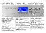
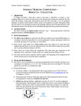
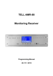
ENIGMA II User Manual
09 / 10 / 2012
POWER LED – ON / OFF status
Blue (steady):
Receiver is on
No light:
Receiver is off
BAT LED – Power supply status
No light:
Power supply OK
Red (steady):
Main power trouble
Red (flashing):
Battery trouble
ERROR LED – Trouble status
No light:
No trouble in the system
Red (steady):
Trouble in the system
(trouble details on LCD)
1 – 8 LED – Telephone line cards / IP cards status
RX LED – Radio receiver card status
No light:
Green (flash):
Red (flash):
Green (flashing):
LINK LED – PC connection status
Green (steady): PC is connected
No light:
PC connection trouble
No receiving / transmission / card
Radio receiving
Radio transmission
During programming
No light:
Green (steady):
Orange (steady):
Orange (flash):
Red (flashing):
Orange (flashing):
No card in given position
Line card / IP card OK
Incoming call
Ringing / Incoming IP event
Telephone / IP line trouble
During IP card programming
DISPLAY LED – Display status (change: DISPLAY button)
Event code display – If DISPLAY led is off
INCOMING CALL – Telephone line card received the
No light:
Event list is displayed on LCD
Green (steady):
Connected cards status menu
Green (flashing):
IP communication status menu
(IP communication status: DISPLAY button push for 3 sec).
F2 (CODES) button to display event codes in event list.
incoming call (incoming event codes can be seen)
LINE ERROR – Card is OK, but line has trouble
ID: xxx – Call is from xxx phone number.
F1, F2, F3, F4 buttons – Function buttons
To use the functions above each buttons (seen on LCD).
◄ and ► buttons – Navigation buttons
For the navigation in menu / event list.
ENTER button – To apply modified settings, or for manual
acknowledge of incoming events.
DISPLAY LED is off – Event list display mode
Restart (RESET) – If DISPLAY led is off
F3 (UTIL) / F3 (RESET) / F3 (RESET).
Troubles – On the top of the LCD actual troubles can be seen.
Event list – If DISPLAY led is off
ACCOUNT – Client account of incoming message (from who)
Note: 0000 client account means receiver internal message.
EVENT – Type of incoming event (what happened)
LINE – Channel of incoming event (1 - 8 = telephone lines / IP
cards; IP = Ethernet; A, B = radio channel; S = receiver internal
message; X1-X8, XA-XB = telephone line number or radio
channel of the additional receiver connected to the receiver unit)
TIME – Receiving time of incoming event
Note: If there is no button push during menu navigation for 10
seconds (configurable), the receiver automatically switches to the
new incoming event.
Date and time setting – If DISPLAY led is off
DISPLAY LED is steady – Connected cards status menu
F4 (SETUP) / F3 (TIME), the values can be modified with F1
(+) and F2 (–) buttons, ◄ and ► buttons can be used to
change position, ENTER button = apply settings.
In this menu basic operations can be made regarding to
telephone line cards, IP cards and radio receiver card.
Character size change – If DISPLAY led is off
F1 (FONT) button, change between 5 or 10 rows display.
CARDS – Telephone line cards / IP cards status
READY – Telephone line card / IP card is OK
RING – Ring on the telephone line card
RADIO – Radio receiver card status
READY – Radio receiver card OK (signal level scale below).
Event codes can be seen during radio receiving, received
signal strength in brackets (7 – minimum, F – excellent).
F1 (MON ON / OFF) – Speaker On / Off
F3 (STATUS) – Card status (and firmware version) checking,
RESET button for card restart.
F4 (HANG UP) – To abort stucked phone call.
Status display signals below radio card field:
COM-A (USB-A) / COM-B (USB-B) – A / B serial ports
status; USB legend if PC is connected through USB.
Note: R signal, if the serial port works only in receiving mode
LPT – Printer status; IPLINK – Ethernet connection status;
AC – Main power status; BATTERY – Battery status.
DISPLAY LED is flashing – IP communication status
IP data – LAN IP address, Port, Gateway, WAN IP address.
SCK = Opened sockets number, TCM = Monitored devices
number. Individual monitoring time before event codes.