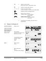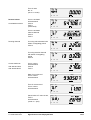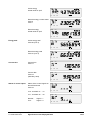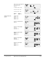
1
Landis & Gyr Combimeter for active and reactive energy User manual Landis & Gyr ZFB / ZMB310 Landis & Gyr ZFB / ZMB405/410 H 1 0200 2035 b en Revision history Information about document indexes, and revisions carried out respectively. Revision a Date 04.05.98 03.02.99 Name/phone D. Opitz - 2892 D. Opitz - 2892 b 30.06.99 D. Opitz - 2892 Comments replaces M13 138 187c E Frontpage faceplate Siemens, page 12 ch. 4.4 Line fuses completed page 14 ch. 4.7 Clamping screws add. Type Z replacement of mercury-wetted reed relay r14 by solid-state relay: Pages 8, 18, 19, 20, 37 and 51. Copyright 1999 by Siemens Metering Ltd. All rights reserved. Quality and environmental approval ISO/EN 9001 ISO/EN 14001 Table of Contents Page 1 General Remarks 5 2 Product Overview 6 3 3.1 3.2 3.3 3.4 Operating Data 7 7 8 8 8 4 4.1 4.2 4.3 4.4 4.5 4.6 4.7 4.8 4.9 4.10 4.11 4.12 5 5.1 5.2 5.3 Siemens Metering H1 0200 2035 b en Operating Limits Outputs Meter Constants Other Data Installation in the Field Mechanical Installation Arrangement of the Seals Front Panel Electrical Installation Terminal Dimensions Configuration of the Terminals Clamping Screws Installation of the Signal Inputs and Outputs Installation of an External Ripple Control Receiver Installation into a Switchboard Synchronisation Connection Diagrams Commissioning and Functional Checks Switching Functions Check Energy Directions Display Check 9 9 9 10 11 13 13 14 14 15 16 16 18 21 22 22 23 6 6.1 6.2 Significance of the Displayed Data 7 Change of Operating Data / Parameterization 30 7.1 7.2 7.3 7.4 7.5 Input of the Operating Data (Set Mode) Formatted Commands Reparameterization Security Concept Service Mode 30 32 32 33 34 Explanation of the Codes and Symbols Example of a Display List Z.B405/410/310CT.. Table of Contents 24 24 25 revision 3/52 8 Resetting (Cumulation) 36 9 9.1 9.2 Communications and Pulse Retransmission 37 37 37 10 10.1 10.2 10.3 Error Messages Retransmission Contacts Communications Interfaces Operating Errors Functional Faults Table of Error Codes 11 11.1 11.2 Installation for Meter Testing 12 12.1 12.2 12.3 12.4 12.5 Meter Testing 13 13.1 13.2 13.3 13.4 Maintenance and Service Parameterization Software Service Software Action by Malfunctions Battery Replacement 49 49 49 49 50 14 Disposal Information 51 15 Appendix 52 52 Voltage Bridge Connection of the Control Inputs Testing of No Load and Starting Current Measurement Times for Meter Testing Testing of the Energy Measurement Calibration at the Customer’s Premises Clip for Scanning Head Operational Overview Siemens Metering H1 0200 2035 b en 40 40 40 41 Z.B405/410/310CT.. Table of Contents 42 43 43 45 45 45 48 48 48 revision 4/52 1 General Remarks The user manual for the product series Landis & Gyr ZFB/ZMB310CT and Landis & Gyr ZFB/ZMB405/410CT (ZFB/ZMB being designated hereafter as Z.B) provides information about the installation, operation, and testing of these modern Siemens Metering combi meters. Please read this user manual carefully before installing the meter. The installation should only be carried out by qualified personnel. Ensure that local safety regulations are adhered to during the process. When installing or opening the meter the connections must be free of voltage. Touching parts under voltage is dangerous to life. The combi meters Z.B310CT and Z.B405/410CT are very easy to handle. The following sections provide a step-by-step guide to installation and commissioning. For a more in-depth specialised knowledge about the function of the Z.B310CT and Z.B405/410CT models, Siemens Metering offers model-specific training courses within the framework of its customer education function. For further information about such training, please contact your local Siemens Metering representative. This user manual deals with general information and does not take into account any of the special country-specific functions. It is intended to serve as the basis for country-specific or language-specific manuals. All technical documents remain the intellectual property of the manufacturer. They may not be copied or reproduced, made known to third parties in any manner whatever, or used for the manufacture of the product itself or components thereof. All data are up-to-date at the time of printing. The right to make modifications is therefore reserved. Conditions of guarantee Siemens Metering Ltd. is obligated for the duration of one year, from the date of invoicing or from the date of readiness for shipment, to repair or replace, as quickly as possible, all parts which become impaired or unusable as a provable consequence of defective material, defective construction, or faulty manufacture. The guarantee is only valid if the meter has been used as intended and the meter electronics have not been interfered with. Faulty meters must be immediately submitted, freight-free, to a representative of Siemens Metering Ltd. Siemens Metering H 1 0200 2035 b en Z.B405/410/310CT.. General Remarks revision 5/52 2 Product Overview The combi meters Z.B405/410CT and Z.B310CT encompass several products which address various requirements related to tariffs and measurement technology. The summary below provides information about the product range offered. The vertical axis of the table indicates the type of tariff structure, while the horizontal axis indicates the type of tariff control. Metering units ZMB ZFB meters for three-phase four-wire networks meters for three-phase three-wire networks 405 transformer connection with accuracy class 0.5S for active energy in accordance with IEC 60687 and class 2 for reactive energy in accordance with IEC 61268 410 transformer connection with accuracy class 1 for active energy in accordance with IEC 61036 and class 2 for reactive energy in accordance with IEC 61268 310 direct connection with accuracy class 1 for active energy in accordance with IEC 61036 and class 2 for reactive energy in accordance with IEC 61268 CT.. AT.. active, reactive, and apparent energy active energy, only for meters with T647 and load profile Tariff units Type of tariff control Tariff functions Tariffs: 8 energy E without stored values Tariffs: 8 energy E 8 demand P 15 stored values per tariff Tariffs: 8 energy E 8 demand P 15 stored values per tariff external integrated time switch T116 - T416 T446 T647 T647 load profiles The entire product range is not offered in certain countries. More detailed information is available from your Siemens Metering representative. Siemens Metering H 1 0200 2035 b en Z.B405/410/310CT.. Product Overview revision 6/52 3 Operating Data The following points must be observed during installation of the meters: 3.1 1. Always install the meters in accordance with the nominal data indicated on the name plate. 2. Always connect the meters in accordance with the connection diagram contained inside the terminal cover. Operating Limits Measurement voltage: min.: max.: 0.8 Un 1.15 Un Power consumption in voltage circuit: typical maximum Maximum current Z.B310: < 2 VA / 2 W per phase 3 VA / 3 W per phase metering thermal: starting current max. 100 A max. 120 A typical 40 mA Power consumption in current circuit: approx. 0.03 VA per phase at Ib = 10 A Maximum current Z.B410: metering thermal: starting current max. 10 A max. 12 A typical 4 mA Power consumption in current circuit: approx. 0.3 VA per phase at In = 5 A Tariff control voltage: min.: max.: 0.8 Ut 1.15 Ut Current per tariff control input: < 4 mA Frequency range: min.: max.: Ambient temperature range: specified operating range: limit range of operation: transport and storage: Insulation strength: > 4 kV at 50 Hz for 1 minute (double insulation strength) Voltage impulse strength: > 8 kV with 1.2/50 µs 0.95 of nominal frequency fn 1.05 of nominal frequency fn -20 to +55 °C -25 to +60 °C -25 to +70 °C Electromagnetic compatibility (EMC): - Electrostatic discharges - Electromagnetic high frequency fields - Electrical fast transient/burst - Radio interference Siemens Metering H 1 0200 2035 b en Z.B405/410/310CT.. Operating Data to IEC 61000-4-2, contact discharges, 8 kV to IEC 61000-4-3, 27 MHz until 500 Mhz, 10 V/m (typical 30 V/m) to IEC 61000-4-4, 2 kV for current and voltage circuits, 1 kV for aux. circ. <40 V to IEC/CISPR 11, Class A equipment revision 7/52 3.2 Outputs Transmitting contact r14 a and transmitting contact of the integration period e - max. loading capacity (AC/DC) - Operating data (AC/DC) - Life time / failure rate - Pulse length / Pulse frequency Contact protection Resistance of closed contact series 2 *series 3 (1999) mercury-wetted reed type relay 250 V, 1 A, 50 VA solid state relay 250 V, 100 mA min. 5 V, 0.1 mA < 0.5 % in 15 years - programmable zinc oxide – protection resistor typ. 30 Ω, max. 50 Ω 3x10⁹ pulses at 50 mA - programmable laid out for 0.1 A *S3: The transmitting contacts r14 or r14a resp. consisting of mercury-wetted reed type relays have been replaced by environmentally friendly solid-state relays on the series 3. The face plates of these meters are marked with “S3”. Loading, output K4 and K5 (e/a): Current loop serial interface CS: 3.3 max.: 250 V, 2 A, 500 VA, 200 W without contact protection in accordance with IEC 61107 max.: 27 V, 20 mA DC Meter Constants Direct connection: ZFB310 ZMB310 Transformer connection: ZFB405/410 ZMB405/410 3.4 Nominal voltage: (voltage range) 3 x 230 V (200 ... 240 V) 3 x 230 / 400 V (202/350 ... 240/415 V) Meter constant R: 3 x 100 V 20,000 pulses/kWh or kvarh 3 x 200 V (200 ... 240 V) 3 x 400 V (350 ... 415 V) 10,000 pulses/kWh or kvarh 3 x 58 / 100 V (58/100 ... 66/115 V) 3 x 115/200 V (115/200 ... 133/230 V) 3 x 230 / 400 V (202/350 ... 240/415 V) 20,000 pulses/kWh or kvarh 1,000 pulses/kWh or kvarh 500 pulses/kWh or kvarh 5,000 pulses/kWh or kvarh 10,000 pulses/kWh or kvarh 5,000 pulses/kWh or kvarh Other Data Gross weight: Packaging: Z.B405 / 410 / 310 approx. 1.6 kg Carton, 250 g protected against falls up to 1 m splashproof IP 52 IP protection class: Operating reserve of calendar clock: - with supercaps (T416/446) 5 days - with battery (T446/647) see 13.4 page 48 Recharging of supercap: max. 3 hours Siemens Metering H 1 0200 2035 b en Z.B405/410/310CT.. Operating Data revision 8/52 Mechanical Installation 6,2 276.5 75 180 219.5 4.1 Installation in the Field 256.5 4 40 60 24 6 77 150 173 Figure 4.1 Dimensional diagram of Z.B405/410/310T The mechanical attachment of the meter is carried out in accordance with current standard practice. The two lower attachment points to the left and right of the terminal block, being separated by 150 mm, conform to the dimensions in accordance with DIN 43 857. The suspension eyelet permits an open or hidden attachment of the meter, and the height of the suspension triangle configuration is 180 mm or 162 mm. Using these three attachment points, the meter can be mechanically mounted on a switchboard or similar installation. The measurementrelated characteristics of the meter remain unaffected in the presence of skewed, or even horizontal installation. 4.2 Arrangement of the Seals Utility own seal for front panel (can also used seal component as per figure 4.3) Calibration seal Calibration seal Utility own seals for terminal cover Figure 4.2 Siemens Metering H 1 0200 2035 b en Arrangement of the seals Z.B405/410/310CT.. Installation in the Field revision 9/52 The meters of the Z.B series are protected from unauthorised access by a total of 5 seals (see Figure 4.2): • Two official seals (calibration seals) are situated to the left and right, respectively, of the lower end of the upper enclosure half. They protect the calibration validity of the meter. • Two further seals (utility own seals) prevent interference with the terminal lid or the terminals which are situated below that lid. • A seal (utility own seal) situated between the two calibration seals prevents the front cover from being hinged upwards and thus secures the dial face and the reset button. An additional component, which is easy to install, allows the use of a standard padlock instead of a utility seal. (see Figure 4.3). Insert in position 1 Seal component Front panel Terminal cover Side view Figure 4.3 And turn in position 2 Position 1 Position 2 Front view Seal component for use with padlock Slide the seal component into the vertical slot at an angle, as shown, (position 1) until it contacts the rear wall. Now turn the component until it is horizontal and slide it down into position 2 as illustrated. The two bulges firmly fix the seal component into the lateral grooves. 4.3 Front Panel When the utility own seal or the padlock on the front panel is opened, the cover can be swung up beyond the horizontal position until it reaches a fixed position. The opened front panel allows the reset button to be activated and the paper labels or the name plate to be replaced. On closing the panel, the resistance of the cam which holds the cover in the horizontal position must be overcome. This is accompanied by a characteristic cracking sound. Siemens Metering H 1 0200 2035 b en Z.B405/410/310CT.. Installation in the Field revision 10/52 Raised Face plate insert in the reverse of factory seal if use seal component Front lid Locked in place insert seal component Pad lock (side view) Closed Figure 4.4 4.4 Front cover opened Electrical Installation The meter must be connected in accordance with the connection diagram inside the terminal cover. The terminals of the metering unit will have the following aperture diameters, depending on the model : Diameter Limiting current Terminal separation Conductor crosssection Z.B405/410 5.2 mm 10 A 10 mm max. 5 mm ∅ (dia.) Z.B310 7.2 mm 60 A 13 / 16 mm 25 mm2 cable Z.B310 8.5 mm 100 A 14.3 / 14,7 mm 35 mm2 cable 25 mm2 flex Flex always fitted with cable end cap Ensure that the terminal screws of the metering unit (phase connections) are always tightened to the indicated torque as per section 4.7. Badly tightened screws at the phase connections can result in increased power losses at the terminals, and thus unwanted heating. A contact resistance of 1 mΩ will cause a power loss of 10 W at 100 A. If the cross section of the connection wires does not correspond with the maximum current of the meter, i. e. 2.5 mm2 for a direct-connected meter, please ensure that the connection wires are securely fitted. Siemens Metering H 1 0200 2035 b en Z.B405/410/310CT.. Installation in the Field revision 11/52 T Temperature rise [K] 30 Measured on outside of housing in accordance with IEC 1036 2 Cable All 3 phases switched on 20 3 10 40 20 60 80 100 Phase current Figure 4.5 [A] Temperature rise vs phase current, measured on the outside of the housing CAUTION When connected to low level voltage, the meter voltage circuits are connected directly to the phases. The only protection is the 100 A primary fuses. A very high current will result if a short circuit occurs in the meter, between the phases, or between a phase and neutral. The resulting electrical arc will destroy the meter and could damage the surrounding area, e.g. by fire. A line fuse, maximum value = 10 A, must be installed in each voltage circuit of low voltage level meters connected to current transformers. The location of the fuses is shown in figure 4.6 line fuses max. 10 A primary fuses > 100 A 1 2 3 4 5 6 7 8 9 11 k l k l k l K L K L K L L1 L2 L3 N Siemens Metering H 1 0200 2035 b en Z.B405/410/310CT.. Installation in the Field revision 12/52 4.5 Terminal Dimensions 8.5 Terminal for direct connection Z.B310 up to 100 A ...100 A 13.15 19.65 14.7 14.3 14.7 14.3 14.7 14.3 Z.B310 13 30.35 7,2 ...80 A up to 80 A 12.5 19 Figure 4.6 13 16 13 16 16 13 35 9 Terminal dimensions for universal terminal, ZMB310 5,2 Terminal for transformer connection up to 10 A Z.B405/410 12,5 16 Figure 4.7 4.6 10 10 10 10 10 10 10 10 10 44 Terminal dimensions for terminal for transformer connection, Z.B405/410CT Configuration of the Terminals CS-output +CS/-CS Control inputs CS G E1 E2 KA KB mB/P1 P2/E3 e U1 I1 U2 I1 I2 U3 I2 I3 N I3 r14a/r14a Retransmitting contact Integrating period Retransmitting contact Fixed valence pulses a1 / a2 Retransmitting contact Time functions Voltage connections Current connections Figure 4.8 Siemens Metering H 1 0200 2035 b en Terminal configuration illustrated on a ZMB405/410CT416... Z.B405/410/310CT.. Installation in the Field revision 13/52 4.7 Clamping Screws Combination clamping screw for direct connection: Dimensions: M6 x 14, head diameter max. 6.6 mm Slot 0.8 +0.2/+0.06 mm Type H, size 2, as per ISO-4757-1983 resp. DIN 7962 - H2 (Philips crossed slot) or Z.B310 Type Z, size 2, as per ISO-4757-1983 resp. DIN 7962 - Z2 (Pozidriv crossed slot) Combination clamping screw for transformer connection: Z.B410 Screwdriver: for crossed slot, tip as per DIN 5260-PH2/PZ2 for slot, blade or bit 0.8 x 5.5 mm screwdriver size 3 (CH) or as per DIN 5264 Tightening torque: max. 3.0 Nm Dimensions: M4 x 8, head diameter max. 5.5 mm Slot type H, size 2, as per ISO-4757 or DIN 7962 - H2 Screwdriver: for crossed slot, tip as per DIN 5260-PH2 for slot, blade or tip 0.8 x 5.5 mm Screwdriver size 3 (CH) or as per DIN 5264 Tightening torque: max. 1.7 Nm The combination clamping screw permits the use of various screwdrivers, including automatic screwdrivers. 4.8 Installation of the Signal Inputs and Outputs The connection of the control signals and output signals takes place quickly and reliably with the aid of screw-less terminals based on the principle of the WAGO brand cage tension spring. With the aid of a standard size 1 screwdriver (or a WAGO screwdriver), insert the cables into the apertures provided for the purpose in the WAGO terminal. Figure 4.9 below demonstrates this process. Using a light upwards movement, press the screwdriver into the upper aperture of the terminal, thus causing the contact components immediately underneath to open up. Now insert the cable end and then withdraw the screwdriver. Screwdriver 1 Insert and push in with a light upward turn Insert connecting wire 2 approx. 4 mm 3 Figure 4.9 Siemens Metering H 1 0200 2035 b en Fastened Wire connection with WAGO terminals Z.B405/410/310CT.. Installation in the Field revision 14/52 Disassembly is performed in a similar manner. Instead of inserting the end of the cable, pull the cable out of the opened terminal. On no account must the cable be pulled out of a closed terminal. If this is performed, there is a danger of damaging the terminal. This type of wiring represents a modern technique which is widely accepted in the area of installation and guarantees a high level of contact quality. Wires and flexes (the latter always fitted with end caps) of up to 2.5 mm2 can be connected. To allow looping of connections, single terminals have been implemented as dual terminals, although only one wire can be connected to each pole. The terminals have been numbered in accordance with the connection diagram. 4.9 Installation of an External Ripple Control Receiver FTT4 resp. 5 100 63 FTT4 187 75 FTT5 FTT5: 122 Terminal cover for FTT4 resp. FTT5 Figure 4.11 FTT4: 134 Installation of an external ripple control receiver FTT4 or FTT5 from Siemens Metering In the event of space shortage on the meter switchboard, an external ripple control receiver, model FTT4 or 5 from Siemens Metering, can be installed over the metering unit terminals as shown above. For this, a suitable terminal socket is required (order number 4 111 2361 0) Siemens Metering H 1 0200 2035 b en Z.B405/410/310CT.. Installation in the Field revision 15/52 4.10 Installation into a Switchboard The meters in the Z.B405/410CT and Z.B310CT series can be mounted on a switch-board using a mounting frame as illustrated below. The components required for this purpose are available as an installation kit from Siemens Metering (order number 4 107 5215 0). 232 172 Meter 143 246 30 Attachment of meter to mounting frame Mounting frame Attachment of mounting frame 212 8 Switchboard R5 ma x 210 226 180 5 Figure 4.11 Installation into switchboards 4.11 Synchronization In tariff units with integrated time switch T446 and T647 the clock module can be synchronized. To achieve this, a signal input SYN15 is installed in the upper terminal row. Alternatively, a utility can use one of the relays K4 or K5 (option) as a synchronization output SYN60 to realize a master-slave operation. In this case, the following should be considered: Siemens Metering H 1 0200 2035 b en Z.B405/410/310CT.. Installation in the Field revision 16/52 Synchronization input SYN15 The SYN15 input requires the following signal conditions: k x 15 minutes k = 1 to 96 >= 10s VAC filter time 0.5 to 2 s reset clock time set clock time Figure 4.12 0V Signal on synchronization input SYN15 If the synchronization changes the time by more then 2 seconds, the tariff unit will start a new integrating period, as long as it is parameterized to do so (see information on your model). Tariff units produced up to version 14 are not equipped with new start. Resetting the time can lengthen the integrating period by a short amount. Synchronization output SYN60 The SYN60 output requires the following signal conditions: 60 min 10 s contact a XX.00.00 Figure 4.13 XX.00.10 Signal on synchronization output SYN60 A synchronization signal allways occurs on the full hour. Before synchronization can start, all time switches must be set to the correct time and date. Siemens Metering H 1 0200 2035 b en Z.B405/410/310CT.. Installation in the Field revision 17/52 4.12 Connection Diagrams Examples Tariff terminal numbering, depending on model Explanation of abbreviations G: E1, E2; E3: KA and KB: mB Common of control inputs Control inputs for energy tariffs Control inputs for reset Control input for integrating period and/or inhibition of demand measurement Control inputs for demand tariffs P1 and P2: a: e: CS: Retransmission of a control signal with working contact Retransmission, integrating period Interface for data readout (CS : Current loop serial interface) Retransmission, fixed valency pulses, via solid-state relay (S0 interface in accordance with DIN 43 864) r14a: SYN15 Synchronization of clock module (for special applications) DC T416/446/647 90 90 K1 K2 r14a r14a K3 r14a AC 90 G E1 E2 KA KB mB P1P2 E3 CS + 1 2 2 2 k 3 4 5 l 5 5 k 6 7 8 8 9 11 l k l L K L 11 30 31 20 21 22 32 33 40 40 41 41 42 42 43 43 44 44 45 46 47 48 V L1 L2 L3 N L K K x xx x x x Connection diagram, ZMB410CT...eCSr14ar14ar14a S2 Figure 4.14 DC T416/446/647 K3 90 90 r14a r14a r14a AC K1 K2 90 G CS 1 2 2 2 3 4 5 5 5 6 7 8 8 9 11 k l k l k l K L K L K L 11 30 31 20 21 22 E1 E2 KA KB mB P1P2 E3 + 32 33 40 40 41 41 42 42 43 43 44 44 45 46 47 48 V L1 L2 L3 N Figure 4.15 Siemens Metering H 1 0200 2035 b en x xx x x x Connection diagram, ZMB410CT...eCSr14ar14ar14a S3 Z.B405/410/310CT.. Installation in the Field revision 18/52 DC T416/446/647 AC a a K1 e K2 r14a K5 K3 r14a K4 90 90 G E1 E2 KA KB mB P1 P2 E3 CS + 32 33 40 40 41 41 42 42 43 43 44 44 45 46 47 48 1 2 2 2 3 4 5 5 5 6 7 8 8 9 u v u v k l k l U V U V K L K L 30 31 20 21 22 50 51 52 V L1 L2 L3 x Figure 4.16 x K2 x K1 K3 Connection diagram of ZFB410CT...a2eCSr14ar14a S2 DC T416/446/647 a a r14a K5 e K4 r14a AC 90 90 G 1 2 2 2 3 4 5 5 5 6 7 8 8 30 31 20 21 22 9 u v u v k l k l U V U V K L K L E1 E2 KA KB mB P1 P2 E3 CS + 32 33 40 40 41 41 42 42 43 43 44 44 45 46 47 48 50 51 52 V L1 L2 L3 x K3 Figure 4.17 Siemens Metering H 1 0200 2035 b en K1 x K2 x Connection diagram of ZFB410CT...a2eCSr14ar14a S3 Z.B405/410/310CT.. Installation in the Field revision 19/52 DC T416/446/647 90 K3 K1 K2 e r14a r14a AC 90 90 G E1 SYN15 CS - + 2 2 1 5 3 5 12 9 10 7 30 31 20 21 22 11 8 6 4 32 33 40 40 41 41 42 42 43 43 44 44 L1 x L2 x x x x L3 N x V Connection diagram of ZMB310CT...eCSr14ar14a S2 Figure 4.18 DC T416/446/647 90 e r14a r14a AC K3 K1 K2 90 90 G E1 SYN15 CS + 2 1 2 5 3 4 5 11 8 6 7 9 10 L1 30 31 20 21 22 12 x L2 x x x x L3 N Figure 4.19 Siemens Metering H 1 0200 2035 b en - 32 33 40 40 41 41 42 42 43 43 44 44 x V Connection diagram of ZMB310CT...eCSr14ar14a S3 Z.B405/410/310CT.. Installation in the Field revision 20/52 5 Commissioning and Functional Checks Neutralization of KA and KB Before connecting the meter to mains voltage, the control inputs KA and KB can be neutralized by means of a formatted command (see 7.2) to prevent an unintentional reset. Indication of phase voltages As soon as the meter is connected to mains voltage, the corresponding indicators show the presence of the phase voltages. The codes L1, L2, and L3 in the LCD serve as indicators. In the ZFB meters for three-phase three-wire mains, the central L2 code is not displayed, since the middle phase acts as the reference voltage. Name plate (behind front panel) Test diodes kWh / kvarh LCD infra-red green Display button Indication of phase voltages Reset button (covered) DFS L1 L2 L3 Optical interface Window for paper lables Figure 5.1 Front view of Z.B410CT and Z.B310CT All Z.B meters make use of so-called supercaps to assure the continuity of operation of the calendar clock in the event of voltage interruptions. After connection of the mains voltage, there is a lag of between 5 and 10 seconds before the meter will become functional and the display appears. Siemens Metering H 1 0200 2035 b en Z.B405/410/310CT.. Commissioning and Functional Checks revision 21/52 Time to charge supercap 5.1 At first installation or after prolonged voltage break-down, the meter requires up to 3 hours, and if fitted with a time switch up to 5 hours, to fully charge the supercap. Back-up during prolonged voltage break-down (typically 5 days, pre April 94 typically 12 hours) can only be guaranteed when the supercap is fully charged. Switching Functions Check During installation of the meter, take the opportunity to check whether the meter has been connected correctly. Determine whether all voltages are present by checking for the presence of the codes L1, L2, and L3 for the ZMB or the codes L1 and L3 for the ZFB. Energy direction check Furthermore, check that each phase is counting correctly. The two arrows for the direction of energy at the top left of the display indicate the active (Watt) and reactive (var) energy direction. The arrows must point to the right for the positive energy direction (import). This corresponds with the direction of rotation of Ferraris meters. In the event of a low load, the meter will require a certain time to determine the direction of energy. For how to distinguish inductive and capacitive reactive energy, see Figure 5.2. Test diodes Functioning of the meter is indicated by flashing of the two green test diodes at top right. These diodes will light continuously if there is no load (see also section 12, Meter Testing). An infra-red diode is situated next to each green test diode. It operates in parallel with the green diode and is provided to allow meter testing with an optical scanning head. 5.2 Energy Directions For export of energy (sum of all phases negative), the arrow which appears at the top left of the display will point to the left. Import of active energy Watt var with inductive reactive part Watt var with capacitive reactive part Export of active energy Watt var with inductive reactive part Watt var with capacitive reactive part Figure 5.2 Siemens Metering H 1 0200 2035 b en LCD display of energy direction Z.B405/410/310CT.. Commissioning and Functional Checks revision 22/52 5.3 Display Check After confirming the correct connection of the meter, test the display list. The values indicated in the LCD should be as follows: Operating display 1. The meter shows the operating display, as long as the display button beside the display is not activated. This display can consist, depending on the model, of a single value or several values which follow each other at an interval determined by the parameterization (usually 15 seconds). Display check 2. Now press the display button - the first item to be displayed is the display check. Check that all LCD symbols, and in particular all numerical segments, are present. The significance of the symbols is described in section 6 below. 3. After approx. 5 seconds, or after further activation of the display button, the display switches over to the next display mode, which is generally the identification number. If the display check is followed by an error message, then proceed in accordance with the information in section 10, as long as the number indicated exceeds 00 (eg. F 08). For every additional press of the display button, the display proceeds to the next value to be displayed. Fast sweep 4. Prolonged pressing of the button (longer than 1 s) causes the stored values to be skipped. 5. With continuous pressing of the button, all main values intended to be displayed will be shown at 1 second intervals. Check the indicated values for completeness and correct sequence in accordance with your customer-specific parameterization (see information on the face plate). Siemens Metering H 1 0200 2035 b en Z.B405/410/310CT.. Commissioning and Functional Checks revision 23/52 6 Significance of the Displayed Data The LCD display of the Z.B410CT and Z.B310CT provides a simple and comprehensive representation of the various types of data and additional information. The identification of the individual display patterns takes place by means of codes and/or easily recognizable symbols. Watt var MAX T tm L1 Figure 6.1 6.1 L2 10 6 var M L3 1 2 Display check, T416/446/647 Explanation of the Codes and Symbols Watt var All segments for the display of energy direction to right : positive, i.e. import to left : negative, i.e. export Watt : active energy var : reactive energy Resetting currently barred 1) Display of a delta value (the energy consumption between 2 reset events, instead of energy status) 1) Display of a cumulative maximum value (together with MAX and e.g. kW) or of an energy total value (with e.g. kWh) MAX Display of a maximum or cumulative maximum demand All segments for the display of energy and demand units Unit for active demand (without h) and energy Unit for reactive demand (without h) and energy written "VAr" instead of the normal "var" Unit for apparent demand (without h) and energy Representation of larger quantity of energy and demand All segments for the representation of codes, tariffs, and stored values T Siemens Metering H 1 0200 2035 b en 1) Display of an active tariff 1) Display of a tariff value Z.B405/410/310CT.. Significance of the Displayed Data revision 24/52 tm 1) Meter is in service mode flashing when meter in the calibration mode M 1) Display of a stored value (memory) L1 L2 L3 Display of the phase voltages. L2 does not appear for 3-phase 3-wire meters (ZFB). Flashes in event of a possible time error Display of relay contact K4 (working contact) symbol displayed : contact closed Display of relay contact K5 (working contact) no symbol displayed : contact open 1 2 1) 6.2 If this appears in the display, the symbol can be parameterized. Example of a Display List General information Valid for this example: Watt and var positive Phase voltages L1, L2, and L3 are present Relay K4 closed Relay K5 open Display check Watt T tm L1 Error message (generally only appears in the presence of an error) 1st identification number (customer number) Code 0 Line 1 Reset counter n Code 1 Date of reset event No. 47 (31st March 1993, midnight) Watt L1 Siemens Metering H 1 0200 2035 b en Z.B405/410/310CT.. Significance of the Displayed Data 1 L3 1 L3 1 L3 1 L3 1 L2 2 var L2 Watt L1 L3 var Watt L1 MAX M L2 Watt L1 Reset var var L2 var L2 revision 25/52 Time of reset No. 47 (24:00 => 00:00) Watt L1 Demand values Cumulated maximum P max cumulated active demand Code 2 Tariff 1 (active tariff) P max cumulated reactive demand Code 3 Tariff 1 L2 Watt P running active demand with status of integrating period Code 4 Watt with date and time, with stored values P max current active demand Code 6 Tariff 1 Watt 1 var MAX Watt 1 L3 1 L3 1 var L2 Watt L3 var L2 var MAX T L2 Watt L3 1 var MAX T L1 Time of occurrence of P max current active demand L3 L2 L1 Date of occurrence of P max current active demand MAX T L1 Current maximum 1 var L2 L1 L1 P running reactive demand with status of integrating period Code 5 L3 T L1 Running demand var L2 Watt L3 1 var MAX T L1 Stored value of P max current, Tariff 1 active demand (month 4 = April) L2 Watt Siemens Metering H 1 0200 2035 b en Z.B405/410/310CT.. Significance of the Displayed Data 1 var T L1 L3 MAX M L2 L3 1 revision 26/52 Date of occurrence of P max in April active demand Watt var T M L1 Time of occurrence of P max in April active demand L2 Watt L3 Watt Watt L3 Watt L3 L2 Watt MAX M L2 Watt L3 var Watt 1 MAX M L2 L3 1 var MAX M L2 Watt 1 var T L3 1 var T L1 Siemens Metering H 1 0200 2035 b en MAX L3 T L1 Active energy current status Code 8 Tariff 1 1 var T Energy values MAX T L1 Time of occurrence of P max in April reactive demand 1 var L2 L1 Date of occurrence of P max in April reactive demand MAX T L1 Stored value of P max, Tariff 1 reactive demand (month 4 = April) 1 var L2 L1 Time of occurrence of P max current reactive demand L3 T L1 Date of occurrence of P max current reactive demand MAX M L2 L1 1 var T P max current Code 7 Tariff 1 reactive demand MAX Z.B405/410/310CT.. Significance of the Displayed Data L2 L3 1 revision 27/52 Active energy stored value for April Watt var M T L1 Reactive energy current status Code 9 Tariff 1 L2 Watt L2 Watt L1 Active energy total Code 20 (or 8.0) Watt L1 Reactive energy total Code 21 (or 9.0) Watt L1 Current time Current time Code 11 Watt L1 Current date Code 12 (20th May 1993) Watt L1 Status of control inputs Status of the control signals on the tariff terminals Code 16 Watt 16.0 : terminals 41 ... 44 L1 16.1 : terminals 45 ... 48 Number : Line : Watt 1 var M L2 L3 1 L3 1 L3 1 L3 1 L3 1 L3 1 var L2 var L2 var L2 var L2 var L2 var Signal = 1 Signal = 0 L1 Siemens Metering H 1 0200 2035 b en L3 var T Energy total 1 T L1 Reactive energy stored value for April L3 Z.B405/410/310CT.. Significance of the Displayed Data L2 L3 1 revision 28/52 Status of the control signals on the microprocessor Code 17 Watt 9 = mB, 8 = KA, 7 = KB L1 6 = P3, 5 = P2, 4 = P1 Watt var L2 L3 1 L3 1 L3 1 L3 1 L3 1 L3 1 L3 1 L3 1 var 3 = E3, 2 = E2, 1 = E1 Number : Line : Voltage values and events Signal = 1 Signal = 0 Voltage value Phase 1 = L1 Phase 2 = L2 Phase 3 = L3 L1 Watt L1 Number of voltage failures Code 71 Watt L1 Number of undervoltages Code 72 all phases = .0 Watt L1 Number of undervoltages Phase 1 = .1 Phase 2 = .2 Phase 3 = .3 Watt L1 Number of overvoltages Code 73 all phases = .0 Watt L1 Number of overvoltages Phase 1 = .1 Phase 2 = .2 Phase 3 = .3 Watt L1 Siemens Metering H 1 0200 2035 b en Z.B405/410/310CT.. Significance of the Displayed Data L2 var L2 var L2 var L2 var L2 var L2 var L2 revision 29/52 7 7.1 Change Operating Data / Parameterization Input new Operating Data (Set Mode) All meters in the Z.B405/410CT and Z.B310CT series permit the input of operating data via the optical interface by means of a hand-held terminal or PC. However, it is not planned also to input the operating data via the display and reset buttons in combi meters. The following operating data can be modified as long as they have been released for modification in the parameterization process: - set identification number (customer number) - reset / set reset counter (delete) - reset energy and demand values - reset stored values - reset error code - reset counter of under- and overvoltages - set uncoded password P1 - set time and date Set, in this context, means to enter a new value (status) or zeros (reset). Entry into the set mode If you wish to enter the set mode via the two buttons, proceed as follows : Security level SL3 as per 7.4 1. First read through the following steps, observing the indicated time delays during execution of the steps. 2. Remove the utility own seal from the front panel and flip the front panel to the open position. 3. Starting from the operating display mode, briefly press the display button the display check will appear. 4. Within the next second, continuously press the reset button. Do not release it during the following steps 5. and 6. 5. 1 to 2 seconds after the pressing of the reset button, briefly press the display button again. 6. After a further 2 to 3 seconds, the display will again change to the image with the “quotes” (see Figure 7.1). Now release the reset button. Entry into the set mode has now been achieved. The operation with formatted commands is now possible as well as a reparameterization, but only when this is allowed in the set mode. During entry into the set mode no reset takes place. Siemens Metering H 1 0200 2035 b en Z.B405/410/310CT.. Change Operating Data / Parameterization revision 30/52 Display Reset button button Display Watt L1 var L2 Watt L1 L2 R A R A R L3 var T tm A <1s MAX M L3 1 press 2 2-3s A briefly press after 1 to 2 seconds Watt var T tm L1 L2 A R A MAX M L3 1 keep released 2 2-3s Display changes after 2 to 3 seconds R release R Figure 7.1 Entry into set mode Exit set mode You can exit the set mode by pressing the reset button until the operating display appears (3 to 4 seconds). Error message 08 If you leave the meter in the set mode, it will exit this mode of its own accord after a certain time (e.g. 15 minutes). In this event, an error message F.....08 will appear in the display. The error message 08 will also appear if the voltage is interrupted during the setting process. It shows that the data is not completed. The error message can be cancelled by again entering the set mode and exiting it as described above. Siemens Metering H 1 0200 2035 b en Z.B405/410/310CT.. Change Operating Data / Parameterization revision 31/52 7.2 Formatted Commands The meters of the Z.B405/410CT and Z.B310CT series are fitted with an internal command interpreter in accordance with IEC 61107. This interpreter reads a command sent to the meter via the optical or CS interface (formatted command) and automatically triggers the required operation. The advantage of this formatted or standard command lies in the fact that a uniform command will carry out the same operation in all of the above-mentioned meters. This results in standardisation on the part of the service instruments (hand-held terminal, PC, etc.). The command “Clear Stored Values”, for example, clears the stored values for all instruments of the ZMB series. The various commands are assigned to one of the security levels in section 7.4 via the parameterization process. Thus you can only clear the stored values if you have the appropriate access authorization. Formatted commands FORMAGYR 7.3 - carry out reset - set identification numbers (customer number) - set time and date - read time and date - reset stored values (delete) - set or change passwords - reset energy register, demand register, energy total register - reset / set reset counter - reset error message - switch calibration mode on / off - reset battery timer (only for meters with T446 and T647) - neutralize inputs KA and KB - read out load profile (T647 only) - reset load profile (T647 only) Under this designation, Siemens Metering supplies simple software which allows the application of the formatted commands. Its use requires an IBM-compatible PC with 386 or greater processor. The program is menu-driven and encompasses all currently known formatted commands. Reparameterization Reparameterization can be done at the factory (authorized laboratory) or on-site. The assistance of the parameterization and service software developed by Siemens Metering allows you to obtain full flexibility with regard to modification of the various parameters (reparameterization). Siemens Metering H 1 0200 2035 b en Z.B405/410/310CT.. Change Operating Data / Parameterization revision 32/52 Reparameterization on site On-site reparameterization is normally carried out by entering the set mode as described in section 7.1, as long as it is enabled, and requires the aid of a handheld terminal or laptop computer. In the process you load the parameter file, which has been prepared at the factory, into the meter via the optical interface. With the same hand-held terminal or laptop computer and the appropriate parameterization software, you are in a position to read a parameterization installed in a Z.B meter, and to proceed to use this in the parameterization software. In special cases, reparameterization is also enabled via the coded password P2. In this situation, refer to the information (data sheet) for your model. 7.4 Security Concept Access authorisation All data and parameters are stored at various security levels in order to protect them from unauthorized overwriting. The security levels differ in the type of access privileges allocated. A readout of the data is basically always possible. The security system of the Z.B series for parameterization and data security (access) consists of the steps described below: Access protection Passwords Access: Buttons under calibration seal S1 under utility own seal without calibration seal P1 Switches S2 Cal T P2 P2 Hand-held terminal Calibration switch Security level SL SL 4 SL 3 or P2 PC SL 2 SL 1 P1 SL 0 autom atic readout Figure 7.2 Siemens Metering H 1 0200 2035 b en Security concept of the combi meters Z.B405/410/310CT.. Change Operating Data / Parameterization revision 33/52 Security levels The various security levels determine which functions are accessible with what access authorisation. As an example, the meter data can be read out without special security. However, a password is required in order to be able to execute formatted commands, or the meter must be opened (remove calibration seals) in order to be able to reparameterize it. In addition to the normal levels, two security levels SE5 and 6 are installed for special applications. They are indepentent to the levels SE0 to 4 and enable access via P2 together with the CS input or P2 together with S1. Security switches S1, S2, and Cal The security switches are situated under the meter cover, i.e. under the calibration seals.The switches S1 and Cal serve exclusively for special country-specific functions and will normally not be used by the utilities. Functions which are protected by S2 can only be executed with an opened meter. Push buttons T At this level, those functions and in particular data are stored which are accessible via the two buttons (display and reset button), which are operated in the manner described in section 7.1. Password P2 The password P2, coded specifically by manufacturer, represents a higher level of security than the uncoded password P1. It can only be used with equipment (hand-held terminals) or with Siemens Metering software. A meter-specific algorithm calculates the ultimate password which finally grants access. Password P1 The uncoded password P1 consists of an 8-digit number which is sent to the meter by an instrument (T3000® or PC). If the string of digits agrees with that of the meter, the meter will grant access to security level 1. Wrong password After the 15th attempt to enter a wrong password P1 or P2, the meter’s functions will be blocked and it will issue the error message F 02 (see section 10, Error Messages). Up until midnight on that day, the meter saves every entry requiring one or both passwords. 7.5 Service Mode In the service mode, the display list generally encompasses more data than it does in normal operation. It is primarily intended for on-site checking purposes. If you wish to enter the service mode via the two buttons, proceed as follows: Entry into the service mode Siemens Metering H 1 0200 2035 b en 1. First read through the following steps and, while carrying them out, observe the indicated time intervals. 2. Remove the utility own seal from the front panel and flip the front panel open. 3. Starting from the operating display, press the reset button continuously and do not release it during following steps 4. and 5.. Z.B405/410/310CT.. Change Operating Data / Parameterization revision 34/52 4. 2 to 3 seconds after pressing the reset button, briefly press additionally the display button. 5. After a further 2 to 3 seconds, the display will change to the first display image of the expanded display list of the service mode. This display is identified by the code "tm" in the display. Now release the reset button. 6. As for the normal display list, you can skip stored values by means of continuous pressing of the display button (fast scrolling mode). Display Entry into the service mode Watt Display Reset button button var A L1 L2 L3 R R 2-3s A briefly press after 1 to 2 seconds A press R keep pressed A Watt 2-3s var R tm L1 L2 L3 1 release R press again quickly; the continuation menu will follow then Figure 7.4 Entry into the service mode Exiting the service mode You can exit the service mode by pressing the display button until the operating display appears. In case you do not press the display button anymore during approx. 5 min the meter exits the service mode automatically and the operating display returns. Siemens Metering H 1 0200 2035 b en Z.B405/410/310CT.. Change Operating Data / Parameterization revision 35/52 8 Resetting (Cumulation) The meters of the series Z.B405/410CT and Z.B310CT can be reset (cumulated) in the following manner: - remotely controlled via the signal inputs KA and KB - internally via a reset command from the integrated calendar clock - by means of formatted commands via the optical or CS interface - manually, by pressing the reset button The reset button is situated under the front panel and is secured by means of a factory seal (or padlock with seal component as per section 4). Reset block After the activation of the reset button, the meter triggers a reset block which, depending on the parameterization, can last for a period of between 1 minute and up to several hours. During this rest block period, you can not trigger a further reset event. During the duration of the reset block, the key symbol appears in the display. The reset block also follows every remotely or internally initiated reset event. However, a voltage failure will interrupt the reset block. Siemens Metering H 1 0200 2035 b en Z.B405/410/310CT.. Resetting (Cumulation) revision 36/52 9 Communications and Pulse Retransmission Various output signals as well as two communications interfaces provide a futureoriented system capability for the Z.B meters. Observe the output loading capability of the outputs as per section 3. 9.1 Retransmission Contacts r14a contact The r14a contact retransmits the measured energy in the form of fixed-valency pulses. The contact is a solid-state relay. The weighting (in Wh/pulse or kWh/pulse) as well as the duration of the pulses (in ms) are also parameterized in the meter and marked on the name plate. Loading capacity: max. 250 V, 100 mA (AC/DC) e - contact The e-contact retransmits the integrating period. With every new integrating period, the contact opens for 1% of the duration of the integrating period (i.e. for 9 s in an integrating period of 15 min). This output is a so-called break contact (normally closed contact), i.e. it retransmits the integrating period by means of the opening of the contact (signal interruption). Contact capability: a - contact The a-contacts (max. 3 contacts) serve for the retransmission of the control signals which are generated by the integrated time switch. The following control signals may be available: - Tariff switching energy (E1 / E2) - Tariff switching demand (P1 / P2) - Inhibition of maximum demand measurement (B) - Control signal able to be parameterized without time restriction Contact capability: 9.2 max. 250 V, 0.5 A, 30 VA max. 250 V, 2 A, 500 VA, 200 W no contact protection Communications Interfaces CS-interface The CS interface (Current loop Serial interface) is a current-based interface and serves for hard-wired remote readout. It conforms to the standards in accordance with ZVEI, IEC 61107, and DIN 66 258. It processes the same data as the optical interface. Apart from the readout of data, the meter can also be set, parameterized, or service functions carried out via this interface. Siemens Metering H 1 0200 2035 b en Z.B405/410/310CT.. Communications and Pulse Retransmission revision 37/52 The externally applied supply voltage is basically 24V and must not exceed 27 V. This causes a current of 10 to 20 mA to flow. The maximum wiring length should not exceed 10 metres but, under certain circumstances (current > 10 mA), can be longer. Observe polarity, since the output is a transistor output (open-collector circuit). Optical interface This interface serves for the automatic readout of the meter and also complies with the standards in accordance with ZVEI, IEC 61107, and DIN 66 258. You can use the optical interface to readout the meter on-site using a hand-held terminal (e.g. T3000 or M940 from Siemens Metering). In the same manner as with the CS interface, you can also set and parameterize the meter or carry out service functions on the meter via this interface, whether at the factory or on-site. During placement of the readout head, ensure that the cable at the head is pointing downwards. Protocol of a readout During an automatic readout, the data appear in the form described below. The scope of the protocol is contained in the information relating to your model. The following example shows the data from a - ZMB410C with T416 tariff module - Active demand and energy measurement at 2 tariffs - Reactive energy (inductive) measurement at 2 tariffs - 2 stored values for each tariff Protocol Significance of the data /LGZ4ZMB410CT416.xxx Meter identification (serves to identify the meter within the route) .xxx : identification of software version Siemens Metering H 1 0200 2035 b en F(00) Error message 0(000000000000000000000) Identification number 1 (always printed on one line) 99(00000000000000) Identification number 2 Z.B405/410/310CT.. Communications and Pulse Retransmission revision 38/52 1(54) Number of resets 2.1(67082.0*kW) P max cumulated, tariff 1 2.2(12310.5*kW) tariff 2 6.1(342.7*kW)(93-05-21 11:30) P max current, tariff 1 6.1*54(351.8)(93-04-14 14:30) Stored value No. 54 6.1&53(392.7)(93-03-03 15.15) Stored value No. 53 6.2(294.6*kW)(93-05-12 22:00) P max current, tariff 2 6.2*54(255.6)(93-04-24 00:15) Stored value No. 54 6.2&53(245.2)(93-03-19 21:45) Stored value No. 53 8.1(8774964*kWh) Active energy status, tariff 1 8.1*54(8602235) Stored value No. 54 8.1&53(8427926) Stored value No. 53 8.2(5144480*kWh) Active energy status, tariff 2 8.2*54(5134803) Stored value No. 54 8.2&53(5124979) Stored value No. 53 9.1(1820395*kvarh) Reactive energy status, tariff 1 9.1*54(1778866) Stored value No. 54 9.1&53(1739009) Stored value No. 53 9.2(1422427*kvarh) Reactive energy status, tariff 2 9.2*54(1419757) Stored value No. 54 9.2&53(1396234) Stored value No. 53 20(2099015*kWh) Active energy total 21(3118206*kvarh) Reactive energy total 11(11:42:24) Time of readout 12(93-05-25) Date of readout 71(0025) Number of voltage failures 72(0107) Number of undervoltages 73(0287) Number of overvoltages 95(90-07-25) Date of last parameterization ! End of protocol Stored values: Siemens Metering H 1 0200 2035 b en * signifies : reset occurred internally or remotely controlled & signifies : reset was manual Z.B405/410/310CT.. Communications and Pulse Retransmission revision 39/52 10 Error Messages Automatic selfdiagnostic test All meters in the Z.B series regularly carry out a self-diagnostic test in background mode. This test checks the functional capability of all important parts. In the event of a functional fault or operating error, they issue a detailed error code which appears in the display as a two-digit number after the "F". The error code "00" signifies that no error is present. The error messages are described below. 10.1 Operating Error (Single Error) The operating errors do not necessarily point to a malfunction in the meter. The following codes are classed as operating errors: Cancel an error message 01 incomplete parameterization (if this has been carried out independently and/or not using the original parameterization software) 02 access to the data or parameterization denied because of repeated use of an invalid password 08 set mode not exited in an orderly manner You can cancel the error message generated by an oparting error by the formatted command "clear error display". The error messages 01 (incomplete parameterization) and 08 (set mode not exited in an orderly manner) disappear automaticaly by repeating parameterization or entering the set mode and exiting it in an orderly manner. 10.2 Functional Faults (Single Error) A functional fault corresponds to a serious malfunction of the meter. If such a fault occurs, disconnect the meter if it has already been installed and forward it to the nearest authorized service and repair centre (see section 13). The following codes refer to a functional fault: Siemens Metering H 1 0200 2035 b en 01 incomplete parameterization 04 faulty calculated data 10 control fault 20 fault in addressing external memory 40 fault in parameterization data 80 fault in microprocessor Z.B405/410/310CT.. Error Messages revision 40/52 10.3 Table of Error Codes Group 0x Group 1x Group 2x Group 3x Group 4x Groups 5x / 6x / 7x Group 8x Groups 9x / Ax to Fx Siemens Metering H 1 0200 2035 b en First digit Second digit 0 0 no error present 0 1 parameterization incomplete 0 2 access denied in consequence to repeated use of incorrect password 0 3 combination of 01 and 02 0 4 faulty calculated data 0 5/6/7 0 8 0 9 / A to F 1 0 1 1 to 9 A to F 2 0 2 1 to 9 A to F 3 0 3 1 to 9 A to F 4 0 4 1 to 9 A to F combinations of 40 with 01 to 09 and 0A to 0F 5/6/7 0 1 to 9 A to F combinations of the group 4x with the groups 1x / 2x / 3x 8 0 8 1 to 9 A to F combinations of 80 with 01 to 09 and 0A to 0F 9 A/B/C D/E/F 0 1 to 9 A to F combinations of the group 8x with all previous groups Z.B405/410/310CT.. Error Messages Cause of error combination of 04 with 01 / 02 / 03 set mode not exited in orderly manner combinations of 08 with 01 / 02 to 07 control fault combinations of 10 with 01 to 09 and 0A to 0F fault in addressing external memories combinations of 20 with 01 to 09 and 0A to 0F combinations of the groups 1x and 2x combinations of 30 with 01 to 09 and 0A to 0F access and/or parameterization fault fault in microprocessor revision 41/52 11 Installation for Meter Testing Connect the meter to the terminals of the test bench in accordance with the connection diagram supplied in the terminal cover as well as in accordance with the usual test methods. 11.1 Voltage Bridge Closed on Z.B310CT for direct connection Open Current loop M etering circuit board Contact spring Contact spring Current terminal Figure 11.1 Voltage cable Voltage bridge for ZMB310 The voltage bridge represents a considerable innovation for the directly connected meters of the Z.B series. Instead of a screw-terminal bridge, a spring contact connects the voltage circuit of the meter with the phase connection (see left side of Figure 11.1). For the connection of the test voltage, use a cable with a contact pin having a diameter of 2.5 mm and a length of approx. 40 mm (straight or bent). Insert this contact pin into the circular aperture provided for this purpose in the terminal cover above the metering unit terminals. In the process, the pin lifts the spring from the contact tip of the current loop and thus interrupts the connection. Warning The voltage cables must be potential-free during insertion, for reasons of safety. To touch contact pins under voltage is dangerous to life. Siemens Metering H 1 0200 2035 b en Z.B405/410/310CT.. Installation for Meter Testing revision 42/52 When the test is complete, pull the cables with the (potential-free) contact pins out of the terminal cover. The spring closes the contact to the current loop, and thus the voltage bridge, automatically. Do not use any tools such as screwdrivers or cables which might bend or damage the springs in any way. Siemens Metering can supply suitable voltage cables, according to the table below. Pre-warming Thanks to the low temperature sensitivity of the Z.B meters, warming of the meters can be fundamentally dispensed with. Connection voltage Before switching on the supply voltage, ensure that its value complies with the nominal value indicated on the meter. A supply voltage which exceeds the nominal value by 50 % and more can destroy the meter within a short time. Voltage cables 1) Cable type 1) Order number 700 mm, black 4 421 1438 0 700 mm, red 4 421 1440 0 700 mm, green 4 421 1443 0 700 mm, white 4 421 1447 0 700 mm, blue 4 421 1444 0 700 mm, yellow 4 421 1442 0 700 mm, violet 4 421 1445 0 other colours and lengths on request. 11.2 Connection of Control Inputs Connect the control inputs as described in section 4, or use plugs manufactured by the WAGO company which match your terminals. The latter permit a simpler connection of the control inputs. The appropriate components are: 1 WAGO test plug Art. No. 231-127 1 WAGO termination plate Art. No. 231-100 For connection of the CS interface, you can use the following components from WAGO: Siemens Metering H 1 0200 2035 b en 2 WAGO test plugs Art. No. 231-127 1 WAGO termination plate Art. No. 231-100 Z.B405/410/310CT.. Installation for Meter Testing revision 43/52 Always insert these plugs into the upper aperture of the WAGO terminal, i.e. the place where during installation of the meter you insert the screwdriver for purposes of installing the connection cables. Complete test cables can also be obtained from Siemens Metering, using the order numbers shown in the table below. For other test accessories, contact your local Siemens Metering representative. WAGO test cables 1) Siemens Metering H 1 0200 2035 b en Cable type 1) Order number 700 mm, black 4 421 3752 0 700 mm, red 4 421 3754 0 700 mm, green 4 421 3756 0 700 mm, white 4 421 3760 0 700 mm, blue 4 421 3757 0 700 mm, yellow 4 421 3755 0 700 mm, violet 4 421 3758 0 other colours and lengths on request. Z.B405/410/310CT.. Installation for Meter Testing revision 44/52 12 Meter Testing Test conditions Unless otherwise indicated, the following test conditions apply: Nominal voltage Un : as per data on name plate Nominal voltage range : 0.8 ... 1.15 Un Nominal frequency fn : 50 Hz Nominal frequency range : 0.95 ... 1.05 fn Current values : Ambient temperature : loaded on all phases 23 ° C ± 5 ° C 12.1 Testing No Load and Starting Current Testing of no load Test voltage: 1. Disconnect the meter from the mains for at least 10 seconds. 2. Now switch on the test voltage Up and wait for until the test diode has switched to continuous illumination. The maximum waiting time is as follows: - ZMB405/410 - ZFB405/410 - ZMB310 3. Testing of starting current Up = 1.15 Un as per IEC 1036 e.g. Up = 265 V with Un = 230 V 5 min 7 min 9 min Continuous illumination indicates that the meter has no load. The energy status value, therefore, does not change. Load current l : Z.B405/410 Z.B310 5 mA (three-phase) 50 mA (three-phase) Switch on the load current l and the voltage Un (in each case three-phase). After approx. 3.5 minutes, the test diode extinguishes indicating that the meter is no longer in the no load state. A pulse is now issued approximately every 3.5 min. Note cosϕ during this test (approx. 1 for the active part, approx. 0 for the reactive part). The meter uses the sum of the measured energy in all phases in order to set the starting point. 12.2 Measurement Times for Meter Testing For technical reasons, major measurement deviations can occur during brief measurements. We therefore recommend that the following minimum measurement times shown in the following table be adhered to in order to achieve the accuracy indicated. Siemens Metering H 1 0200 2035 b en Z.B405/410/310CT.. Meter Testing revision 45/52 ZFB/ZMB405... Measurement times in seconds load current measurement accuracy ± 0.1% ± 0.05% ± 0.1% ± 0.05% ± 0.1% ± 0.05% ± 0.1% ± 0.05% ± 0.1% ± 0.05% ± 0.1% ± 0.05% ± 0.1% ± 0.05% ± 0.1% ± 0.05% ± 0.1% ± 0.05% ± 0.1% ± 0.05% 1% In cosϕ = 1 1% In cosϕ = 0.5 5% In cosϕ = 1 5% In cosϕ = 0.5 10% In cosϕ = 1 10% In cosϕ = 0.5 20% In cosϕ = 1 20% In cosϕ = 0.5 100% In cosϕ = 1 100% In cosϕ = 0.5 ZFB405 In = 1 A ZMB405 In = 1 A ZFB405 In = 5 A 1261 2522 1261 2522 159 318 159 318 82 163 82 163 48 95 48 95 23 46 23 46 1017 2033 3017 6034 137 274 297 594 72 144 137 274 43 86 72 144 22 44 27 54 905 1810 905 1810 126 252 126 252 68 135 68 135 41 82 41 82 22 43 22 43 ZMB405 In = 5 A 740 1480 2097 4194 110 220 228 456 60 120 110 120 38 76 60 120 21 42 25 50 ZFB/ZMB410... Measurement times in seconds load current measurement accuracy 1% In cosϕ = 1 1% In cosϕ = 0.5 5% In cosϕ = 1 5% In cosϕ = 0.5 10% In cosϕ = 1 10% In cosϕ = 0.5 20% In cosϕ = 1 20% In cosϕ = 0.5 100% In cosϕ = 1 100% In cosϕ = 0.5 Siemens Metering H 1 0200 2035 b en ± 0.1% ± 0.05% ± 0.1% ± 0.05% ± 0.1% ± 0.05% ± 0.1% ± 0.05% ± 0.1% ± 0.05% ± 0.1% ± 0.05% ± 0.1% ± 0.05% ± 0.1% ± 0.05% ± 0.1% ± 0.05% ± 0.1% ± 0.05% ZFB410 In = 1 A ZMB410 In = 1 A ZFB410 In = 5 A ZMB410 In = 5 A 464 928 464 928 73 146 73 146 39 78 39 78 24 47 24 47 12 23 12 23 384 767 1009 2017 64 127 129 257 35 70 64 127 22 43 35 70 11 22 14 27 346 692 346 692 59 118 59 118 33 66 33 66 21 41 21 41 11 22 11 22 289 577 729 1457 52 104 102 203 30 59 52 104 19 38 30 59 11 21 13 25 Z.B405/410/310CT.. Meter Testing revision 46/52 ZFB/ZMB310... Measurement times in seconds ZMB310 In = 10 A measurement accuracy load current 1% In cosϕ = 1 1% In cosϕ = 0.5 5% In cosϕ = 1 5% In cosϕ = 0.5 10% In cosϕ = 1 10% In cosϕ = 0.5 20% In cosϕ = 1 20% In cosϕ = 0.5 100% In cosϕ = 1 100% In cosϕ = 0.5 In =20 A ± 0.1% ± 0.05% ± 0.1% ± 0.05% 3010 10010 289 730 129 289 64 129 19 30 6020 20020 578 1460 257 577 127 257 38 59 1010 3015 129 289 64 130 35 64 14 19 2020 6020 257 577 127 260 70 127 27 38 Use the same measurement time for unbalanced load; a 20 % higher measurement time at cos ϕ = 0.8, the twice measurement time at cos ϕ = 0.5. Take notice of the preheating error at 20 % In and 100 % In. For higher measurement accuracy the measurement times are to be extended. Test diodes As already mentioned in section 5, the two infra-red test diodes at the top right of the meter are provided for testing the meter. They transmit pulses with a duration of approx. 30 ms, which for testing, the rising edge is always important. The pulse frequency at the test diode is calculated from the meter constant, as per section 3. Multiply the meter constant by the desired power and divide the result by 3,600. This gives the number of pulses per second at the particular power level. f-diode = R x P / 3,600 Example: in pulses/s ZMB410 with R = 5000 pulses/kWh Load I = 5 A or 3.5 kW f-diode = 5000 x 3.5 / 3600 pulses/s = approx. 5 pulses/s Siemens Metering H 1 0200 2035 b en Z.B405/410/310CT.. Meter Testing revision 47/52 12.3 Testing the Energy Measurement The testing of energy measurement corresponds to the so-called register meter test for mechanical registers. The value indicated in the LCD, however, lacks the 10ths division per digit usual for the last digits cylinder. One ought, therefore, to observe a 10 times longer measuring duration for the same test. In order to circumvent this, you can switch to a 10 times higher display resolution (and readout) using a formatted command and thus significantly shorten the test duration. The symbol “tm”, which will flash, will appear in the display. You can exit from this calibration mode by using a further formatted command. An interruption of the supply will also result in an exit from the calibration mode. This function of higher resolution is, among other things, a prerequisite for a fully-automatic meter test process. 12.4 Calibration at the Customer’s Premises The meters of the Z.B405/410 and Z.B310 series are calibrated at the factory and do not require any further calibration during their entire service life. Calibration at the customer’s premises is, therefore, not necessary. A recalibration is only allowed in an authorized laboratory with the corresponding equipment and training. Faulty measurement modules can be replaced in a simple manner by new measurement modules as per the service concept. Following such replacement, a new certification of the meter must be carried out. 12.5 Clip for Scanning Head front view side view frontpanel for Z.B405/410/310 reactive energy pulses cover scanning head for Z.B120/210 and Z.B405/410/310 active energy pulses Figure 12.1 Clip for scanning head for meter testing The clip shown above will be used for the application of magnetically fixed scanning heads, e.g. the TVS.. series from Siemens Metering in all Z.B series meters with electronic tariff units T.. . Siemens Metering H 1 0200 2035 b en Z.B405/410/310CT.. Meter Testing revision 48/52 13 Maintenance and Service The meters of the Z.B series fundamentally do not require any maintenance. The models with integrated time switch normally do not incorporate a battery. Replacement is therefore not usually necessary. In the countries with certification requirements, the certification intervals must be observed, as before. 13.1 Parameterization Software For purposes of parameterization as well as for service functions, Siemens Metering offers a parameterization and service software package which is capable of running on IBM-compatible PCs. This comprehensive and user-friendly software package will support you in the flexible management of the meters Z.B405/410 and Z.B310 with integrated tariff units T116, T416, T446 or T647. For detailed information, please contact your nearest Siemens Metering representative. 13.2 Service Software For managing the use of formatted commands, Siemens Metering provides a service software package which runs on IBM-compatible PCs and is designated FORMAGYR. A corresponding Operating Instruction M13 313 195 E-HQ describes the use of this simple software in detail. 13.3 Action by Malfunctions If a malfunction occurs which causes the meter to no longer operate perfectly, proceed as follows: Siemens Metering H 1 0200 2035 b en - If installed, disconnect the meter from the mains. - Package the instrument in such a manner that it can not sustain additional damage in transit. If still available, the best packaging to use is the original packaging. - Do not enclose any loose components. - Describe the fault which you have determined as precisely as possible and indicate the name and telephone number of a contact person for possible enquiries. - If you have re-parameterized the meter, enclose also the new parameterization data on a diskette, so that we can install your own parameterization into the meter after repair of your unit. Otherwise we will install the original (default) parameterization. - Return the meter to Siemens Metering for fault analysis and repair. Z.B405/410/310CT.. Maintenance and Service revision 49/52 13.4 Battery Replacement Meters with tariff unit T647 always contain a battery. For meters with tariff unit T446 (time switch) it depends on the model. The battery is installed above the LCD and is visible when the front panel is opened. Meters produced on and after April 1994 possess a short-circuit bridge (jumper) beside the minus pole of the battery. The jumper enables the battery to be switched off during the time the meter is not in use. The meter is delivered with jumper set according to parameterization and specification sheets Meters produced earlier then April 1994 have no jumper. In these models, the battery could either be supplied separately or already inserted. If already inserted, the meter should be installed into the following few weeks. Battery lifetime Meters produced up to April 1994: (type VARTA) 5 years; 6000 h of it without voltage Meters produced on and after April 1994: (type MAXELL) T446 10 years; 4 years of it without voltage T647 10 years; 1 year of it without voltage Battery replacement 1. When opening the meter the risk of touching CMOS components exists. The necessary safety precautions must be taken to avoid body voltage. 2. Open the cover and open the short circuit bridge - if it is installed - by pulling out the jumper. 3. Carefully remove the battery. Caution: For meters produced up to April 1994, the battery wires are clamped to soldering pins without solder. 4. Shorten the wires of the new battery to 3 to 4 mm and press them into the soldering pins. The plus pole must always be on the left side, the minus pole on the right side. Solder the wires to the pins. 5. Insert the jumper again - if it is present - on the right side and close the cover. 6. Connect the meter to the voltage (one phase will do) and reset the battery counter to zero by means of the formatted command "reset battery counter". After that switch off the voltage again. Make sure that no dirt or splashes of solder can penetrate the meter. Storage For meters to put into storage, steps 5. and 6. should not be performed. The open short circuit bridge guarantees that the battery does not discharged during storage. When the meter is to be inserted in the network, carry out steps 5. and 6. directly before installation. Siemens Metering H 1 0200 2035 b en Z.B405/410/310CT.. Maintenance and Service revision 50/52 14 Disposal Information Before disposal, the critical components of the Z.B series meters should be removed if practicable. The critical components and their disposal is given in the following table: series 2 Component Disposal Condensators (elco, supercap) Special refuse LED, LCD Special refuse Reed relay r14a series 3 (as of 1999) Solid-state relay 1) Special refuse Electronic refuse Printed circuit boards Electronic refuse Plastic parts Separate by material designation (regranulation possible) 1) The retransmission contact r14a makes use of a mercury-wetted contact. Its presence can be recognized by the type designation of the tariff module (e.g. T416eCSr14ar14a). Mercury is a highly toxic material and may on no account make contact with water or ground. Please dispose all not mentioned parts of the meter in accordance with the agreement reached with Siemens Metering or the local regulations. Siemens Metering H 1 0200 2035 b en Z.B405/410/310CT.. Disposal Information revision 51/52 Appendix Operational overview K time out 4s to wait K Operating display A time out end of list K Service mode for readout and display K..K A 4s to wait to finish readout Display check A A error message F08 time out K..K Manual readout A K K K..K A set mode A K Parameterization mode : Display button for manual readout (> 1 s: without stored values) : Reset button K..K A : K approx. 3 s K..K : K : Do not press reset button K approx. 3 s A after approx 1.5 s T: Automatic return to the operating display Figure A.1 Operational overview Proceeding from the operating display you can: • activate the display list for manual readout • enter the set mode via display check to perform fomatted commands or reparameterize the meter • enter the service mode to obtain the expanded data list for readout. Siemens Metering H 1 0200 2035 b en Z.B405/410/310CT.. Appendix revision 52/52