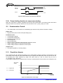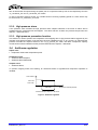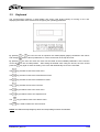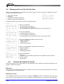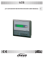
1
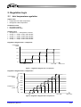
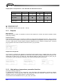
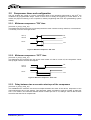
LCS
pCO ADVANCED MICROPROCESSOR USER MANUAL
GB
Index
1.
General description of the application .................................................................... 4
1.1.
Types of units controlled...................................................................................................................4
1.2.
Types of regulation ...........................................................................................................................4
1.3.
Condensation ...................................................................................................................................4
1.4.
Safety devices on the cooling circuit ................................................................................................4
1.5.
System safety features .....................................................................................................................4
1.6.
Optional accessories ........................................................................................................................4
2.
Regulation logic......................................................................................................... 5
2.1.
Inlet temperature regulation .............................................................................................................5
2.1.1.
2.1.2.
2.2.
Compressor times and configuration................................................................................................7
2.2.1.
2.2.2.
2.2.3.
2.2.4.
2.3.
3.
Minimum compressor "ON" time..............................................................................................7
Minimum compressor “OFF” time............................................................................................7
Delay between two successive start-ups of the compressor...................................................7
Power limiting function at compressor starting ........................................................................8
Condensation Control.......................................................................................................................8
2.3.1.
2.3.2.
2.3.3.
2.4.
Setpoint....................................................................................................................................6
High delivery temperature prevention function. .......................................................................6
Regulation diagram..................................................................................................................8
High pressure alarm ................................................................................................................9
High pressure prevention function ...........................................................................................9
Antifreeze regulation.........................................................................................................................9
Start-up and configuration...................................................................................... 10
3.1.
Terminal with keyboard and display ...............................................................................................10
3.2.
Display ............................................................................................................................................10
3.3.
Keyboard ........................................................................................................................................11
3.4.
Starting up the unit for the first time ...............................................................................................12
3.5.
General description of menus ........................................................................................................12
4.
Alarm management ................................................................................................. 14
4.1.
Alarm table .....................................................................................................................................14
4.2.
Alarm history...................................................................................................................................15
2/36
RG66001679_REV.00
5.
Menu tree structure ................................................................................................. 15
5.1.1.
5.1.2.
5.1.3.
5.1.4.
5.1.5.
5.1.6.
5.1.7.
6.
Main menu .............................................................................................................................15
Maintenance menu ..............................................................................................................16
I/O Menu ................................................................................................................................17
Clock menu ..........................................................................................................................18
Setpoint Menu ......................................................................................................................18
Manufacturer menu................................................................................................................19
Alarm menu ..........................................................................................................................29
Architecture of the control system ........................................................................ 31
6.1.
Description of inputs and outputs ...................................................................................................31
6.2.
Optional boards ..............................................................................................................................32
6.2.1.
6.3.
RS485 serial board for supervisory function..........................................................................32
Technical data ................................................................................................................................33
RG66001679_REV.00
3/36
1. General description of the application
The operation of unit with screw compressor is managed by application software installed in the controller on
the unit. The main features of the application software are described below.
1.1. Types of units controlled
The software makes it possible to control air/water single/double-circuit chillers with screw compressors.
1.2. Types of regulation
Proportional regulation on the evaporator input temperature with 4 steps of capacity controlled operation of
compressors. Possibility of adjusting the setpoint remotely.
1.3. Condensation
Modulating condensation control device is based on the reading of the pressure probe and it is independent
for the two circuits.
1.4. Safety devices on the cooling circuit
•
•
•
•
•
•
•
High pressure (pressure switch).
High pressure alarm from the probe
High pressure prevention function
Low pressure (pressure switch).
General compressor alarm (INT69).
High delivery temperature prevention function.
Power limiting function at compressor starting
1.5. System safety features
•
•
•
•
•
Evaporator flow switch
Pumps thermal switch
Condensation fan thermal switch
Remote on/off input
Probe failure alarms
1.6. Optional accessories
• Local supervision by means of RS485 serial board.
• Remote supervision by means of GSM modem or analog modem and modem board
4/36
RG66001679_REV.00
2. Regulation logic
2.1. Inlet temperature regulation
Inputs used:
• Evaporator inlet water temperature
• Refrigerant outlet temperature
Parameters used:
• Regulation setpoint
• Regulation differential
Outputs used:
• Compressor 1 – Compressor 2 On/Off
• Compr. 1 – Compr. 2 CR1 valve On/Off
• Compr. 1 – Compr. 2 CR2 valve On/Off
• Compr. 1 – Compr. 2 CR3 valve On/Off
• Compr. 1 – Compr. 2 CR4 valve On/Off
Regulation diagram with 1 compressor
Compressor
Power
100%
75%
50%
25%
0%
Set
Set + Diff
Water inlet T
Figure 1 : Regulation diagram with 1 compressor
Regulation diagram with 2 compressors
100%
Compressor 2
power
75%
50%
25%
100%
Compressor 1
power
75%
50%
25%
0%
Set
Set + Diff
Water inlet T
Figura 2: Regulation diagram with 2 compressors
RG66001679_REV.00
5/36
Output power correspondence – CR1 CR2 CR3 and CR4 solenoid valves
CR1
CR2
CR3
CR4
Start/Stop
š
š
˜
š
25% power
š
š
˜
ž
50% power
š
˜
š
ž
75% power
˜
š
š
ž
100% power
š
š
š
ž
š = solenoid valve cut off
˜ = solenoid valve cut in
ž = intermittent solenoid valve (10s Off – 10s On)
2.1.1. Setpoint
Main Setpoint
From the m_set_01 mask it is possible to set the main setpoint for summer and winter operation modes
(heat pump version).
Remote Setpoint
From the ID10 digital input it is possible to enable the remote setpoint adjustment function. When contact is
open the function is enabled. In this case, the current setpoint is the algebraic sum of the setpoint in the
m_set_01 mask and the remote setpoint variation determined at the 4-20mA B1 analog input, converted
from a minimum value and a maximum value set in the m_set_02 mask.
m_set_02
+--------------------+
|Setpoint variation |
|from remote:
|
|Min.( 4 mA): 0.0 °C|
|Max.(20 mA): 0.0 °C|
+--------------------+
Setpoint for time periods
The function for changing the setpoint for programmed time periods may be enabled from the "m_fasce"
mask. A time period can be programmed for every day of the week by setting a starting and end time in the
masks from "m_fasce_01" to "m_fasce_07". From the two masks "m_fasce_set_01" and "m_fasce_set_02"
it is possible to enter the setpoints valid within and outside the programmed time periods.
m_fasce_set_01
+--------------------+
|Adjust setpoint
|
|within time band
|
|
|
|Set.:
00.0 °C
|
+--------------------+
m_fasce_set_02
+--------------------+
|Adjust setpoint
|
|outside time band
|
|
|
|Set.:
00.0 °C
|
+--------------------+
m_fascia_01
+--------------------+
|Monday
|
|Start: 00:00
|
|End : 00:00
|
|
|
+--------------------+
2.1.2. High delivery temperature prevention function.
(ref mask m_tempi_comp_03)
To safeguard the efficiency of the compressor, if the refrigerant outlet temperature exceeds the setpoint
entered from the “m_prev_alta_T02” mask, the function for reducing compressor capacity to 25% will be
inhibited to improve oil circulation within the compressor itself.
This function can be enabled from the "m_prev_alta_T01" mask.
6/36
RG66001679_REV.00
2.2. Compressor times and configuration
2
The unit enables the control of a screw compressor. Most of the operations performed by the pCO are
conditioned by programmable delays. Some of them serve to delay the triggering of some alarms or to
assure the proper functioning of the compressor, thereby lengthening their lives and guaranteeing system
stability.
2.2.1. Minimum compressor "ON" time
(ref mask m_tempi_comp_03)
This determines the minimum time (in seconds) the device must continue running: therefore, once activated
it must stay on for the set length of time.
ON
Start-up
demand
OFF
ON
Device
OFF
Figure 3: Minimum compressor “ON” time
2.2.2. Minimum compressor “OFF” time
(ref mask m_tempi_comp_01)
This determines the minimum time the device must remain off. After it is shut off, the compressor cannot
start up again until the set time has elapsed.
ON
Shut off
demand
OFF
ON
Device
OFF
Figure 4: Minimum compressor “OFF” time
2.2.3. Delay between two successive start-ups of the compressor
(ref mask m_tempi_comp_02)
This establishes the minimum time that must elapse between two starts of the device, irrespective of the
read measurement and of the setpoint. This parameter makes it possible to limit the number of starts per
hour. If, for instance, the maximum allowed number of starts per hour is 10, setting a value of 360 seconds
will ensure that this limit is complied with.
RG66001679_REV.00
7/36
ON
Start-up
demand
OFF
ON
Device
OFF
Figure 5: Delay between two successive start-ups
2.2.4. Power limiting function at compressor starting
When the compressor is started, regardless of the inlet water temperature, an override function will reduce
capacity to 25% for an amount of time which may be set from the "m_temp_tempi_03" mask.
2.3. Condensation Control
• The condensation control device is of modulating type, based on the pressure transducer reading.
Inputs used:
• High pressure probe of first circuit (B3 analog input)
Parameters used:
• Condensation Setpoint
• Condensation Differential
• Enabling of prevent function
• Prevent Setpoint
• Prevent Differential
• Delay in device reactivation after triggering of prevent function
• Output voltage relative to minimum inverter speed
• Output voltage relative to maximum inverter speed
Outputs used
• Fan speed regulation (Y1 analog output)
2.3.1. Regulation diagram
The condenser fans are adjusted according to the condensation pressure sensed by the transducer, with
proportional control within the band width defined by the setpoint and differential, which may be set from the
"m_condenser_05" mask, delimited by upper and lower limits (L1 and L2, which may be set in
"m_condenser_06"), see Figure .
It is possible to program the condenser fans to start up a certain amount of time before the compressor; this
Fan power
supply
10 V
L1 = Upper limit
L2 = Lower limit
L1
L2
0V
Set
Set + Diff
Condensation
pressure
Figure 6: Condensation control logic
8/36
RG66001679_REV.00
time as well as the fan speed during the phase prior to compressor start-up can be set respectively from the
“m_condenser_02” and “m_condenser_03” masks.
In case of a broken pressure sensor, an override function can bring operating speed to a value which may
be set from the "m_condenser_04" mask.
2.3.2. High pressure alarm
If the pressure value exceeds the high pressure alarm setpoint selected in the mask an alarm will be
signalled and the compressor will be stopped. The alarm will turn off when the pressure drops below the
setpoint – differential value.
2.3.3. High pressure prevention function
This function is used to prevent the compressor from stopping due to high pressure alarm triggered by the
manually reset pressure switch. If the function has been enabled from the "m_hp_prevent_01" mask and the
pressure exceeds the setpoint entered in the "m_hp_prevent_02" mask, the 100% compressor capacity
control function will be inhibited until the pressure falls below the setpoint – differential
2.4. Antifreeze regulation
Inputs used
• Evaporator outlet water temperature probe.
Parameters used:
• Antifreeze alarm setpoint;
• Antifreeze alarm differential;
Outputs used:
• Antifreeze alarm;
To prevent outgoing water from freezing, an anti-freeze alarm is signalled and compressor operation is
inhibited.
Alarm Status
Alarm ON
Alarm OFF
Antifreeze
Differential
Evaporator outlet temperature
Antifreeze Setpoint Setpoint + diff. band
Figure 7: Antifreeze regulation
RG66001679_REV.00
9/36
3. Start-up and configuration
3.1. Terminal with keyboard and display
Figure 8: Terminal
The user terminal is shown in the picture. It consists of a 4 line x 20 column LCD, keyboard and LEDs
controlled by a microprocessor: from the terminal the user can set the control parameters (setpoint,
differential band, alarm thresholds, etc.) and perform fundamental operations.
The following main operations can be performed via the terminal:
•
•
•
•
initial machine configuration;
modification of main operating parameters;
display of machine status and of all measured data;
display of the alarms detected and a 'buzzer' (that can be disabled);
2
The terminal and the pCO controller are connected via a 6-way telephone cable.
This connection is not essential for standard controller operation.
3.2. Display
The display used is of the 4 line x 20 column LCD type. The data and information regarding operation
alternate as successive windows called masks. It is possible to move around inside the masks using the
terminal keys as described below:
10/36
RG66001679_REV.00
3.3.
Keyboard
The microprocessor features a 4x20 backlit LCD screen (see picture below) for turning on the unit,
displaying the status of the devices and configuring the operating parameters.
By pressing
or
the user can view in sequence the masks (display pages) contained in the menus
and change the numeric value of parameters. A cursor can be seen in the top left corner.
the user can move the cursor into the fields of the modifiable parameters. At the end the
By pressing
cursor will return into its initial position. After setting the desired value using the arrows, the user should
press the
key again to store the setting. The cursor will automatically move to the next field.
The
key provides access to the main menu.
The
key provides access to the manufacturer's menu.
The
key provides access to the maintenance menu.
The
key provides access to the I/O menu.
The
key provides access to the clock menu.
The
key provides access to the setpoint menu.
The
key provides access to the alarms menu.
The
key is used to switch the unit on and off.
NOTE: The LEDs at the top left light up when the corresponding functions are activated.
RG66001679_REV.00
11/36
3.4. Starting up the unit for the first time
When the microprocessor is connected to the power supply, the main menu will be displayed (main). It
contains the following information:
•
•
•
•
current time and date;
unit status;
evaporator inlet water temperature;
evaporator outlet water temperature;
main
+--------------------+
|00:00
00/00/00|
|Unit status: OFF
|
|Watertemp IN 00.0°C|
|Watertemp OUT 00.0°C|
+--------------------+
Pressing the Down key provides access to the following masks:
main_01
+--------------------+
|Compr.1 status: OFF |
|Cool capacity : 000%|
|CR1: OFF
CR2: OFF |
|CR3: OFF
CR4: OFF |
+--------------------+
In main_01 is displayed:
• the on/off status compressor 1
• the cool capacity of compressor 1
• the on/off status of the solenoid valves CR1, CR2, CR3 and CR4
main_02
+--------------------+
|Compr.2 status: OFF |
|Cool capacity : 000 |
|CR1: OFF
CR2: OFF |
|CR3: OFF
CR4: OFF |
+--------------------+
In main_02 is displayed:
• the on/off status compressor 2
• the cool capacity of compressor 2
• the on/off status of the solenoid valves CR1, CR2, CR3 and CR4
main_03
+--------------------+
|Circ.1 conden.status|
|T.supply: 000.0 °C |
|P.supply:
00.0 bar|
|Cond. fan: 000.0 % |
+--------------------+
In main_03 is displayed the status of the first circuit:
• Supply temperature
• Supply pressure
• Condensing fan speed
main_04
+--------------------+
|Circ.2 conden.status|
|T.supply: 000.0 °C |
|P.supply:
00.0 bar|
|Cond. fan: 000.0 % |
+--------------------+
In main_04 is displayed the status of the second circuit:
• Supply temperature
• Supply pressure
• Condensing fan speed
main_05
+--------------------+
|Unit ON/OFF:
OFF |
|Remote consent: YES |
|Pump 1: OFF
|
|Pump 2: OFF
|
+--------------------+
In main_05 is displayed:
• Unit on/off:
Unit ON: if is pressed ON by keyboard and if is enable the remote consent
• Remote consent
• Pumps status
3.5.
General description of menus
General description of the menus featured in the application; all the masks are shown and described in the
Chapter 5 Menu tree structure
Main menu
The main menu is displayed when the unit is started up and consists of the masks described in the section
3.4 Starting up the unit for the first time
Maintenance menu
The maintenance menu can be accessed by pressing key
. It shows the compressor and pump hour
meter as well as the alarm history. It is also possible to set the device hour meter alarm and thresholds,
12/36
RG66001679_REV.00
clear the hour meter, set the current date and time and enable the buzzer. Access is protected by a
maintenance password.
I/O Menu
The I/O menu can be accessed by pressing key
protected by means of a maintenance password.
and shows the system’s inputs and outputs. Access is
Clock menu
The clock menu can be accessed by pressing key
and contains the time and date display.
Setpoint Menu
The Setpoint menu can be accessed by pressing key
and contains the setpoint display. If the user
password is entered it will be possible to change the main setpoint, set the remote setpoint variation limits
and configure the programmed time periods .
Manufacturer menu
The Manufacturer menu can be accessed by pressing key
manufacturer parameters. It is protected by a manufacturer password.
and contains the configuration of
Alarm menu
The Alarm menu can be accessed by pressing key
and gives information about the alarms that have
been triggered. The red LED, provided in the key
, goes on when an alarm is triggered. If the key is
pressed ones the type of alarm triggered is displayed. Pressing the key a second time will reset the alarms .
If the cause of alarm persists, the signalling will be displayed again.
RG66001679_REV.00
13/36
4. Alarm management
4.1. Alarm table
Mask name
Code
Description
Problem solution
m_al_probe_01
AL01
Probe alarm B1
Check probe electric wiring or replace probe
m_al_probe_02
AL02
Probe alarm B2
Check probe electric wiring or replace probe
m_al_probe_03
AL03
Probe alarm B3
Check probe electric wiring or replace probe
m_al_probe_04
AL04
Probe alarm B4
Check probe electric wiring or replace probe
m_al_probe_05
AL05
Probe alarm B5
Check probe electric wiring or replace probe
m_al_probe_06
AL06
Probe alarm B6
Check probe electric wiring or replace probe
m_al_probe_07
AL07
Probe alarm B7
Check probe electric wiring or replace probe
m_al_probe_08
AL08
Probe alarm B8
Check probe electric wiring or replace probe
m_al_probe_09
AL09
Probe alarm B9
Check probe electric wiring or replace probe
m_al_probe_10
AL10
Probe alarm B10
Check probe electric wiring or replace probe
m_al_hp_ps_1
AL11
High pressure alarm circuit 1
Check condenser fan operation Clean condenser coil
m_al_lp_ps_1
AL12
Low pressure alarm circuit 1
Check evaporator fan operation
Check refrigerant level
m_al_int69_1
AL13
AllarmeINT69 compressore 1
Check compressor 1 operation
m_al_hp_probe_1
AL14
High pressure alarm from the
probe circuit 1
Check condenser fan operation Clean condenser coil
m_al_t_cond_1
AL16
Condenser fan thermal switch
alarm circuit 1
Check condenser fan operation
m_al_man_comp_1
AL17
Exceeding compressor 1
operation hour threshold
Check compressor 1 operation
m_al_man_pump_1
AL18
Exceeding pump 1 operation
hour threshold
Check pump 1 operation
m_al_ov_pump_1
AL20
Pump 1 thermal switch alarm
Check pump 1 operation
m_al_antigelo
AL21
Antifreeze alarm
Check pump operation
m_al_flow
AL22
Flow switch alarm
Check pump operation
m_al_hp_ps_2
AL23
High pressure alarm circuit 2
Check condenser fan operation Clean condenser coil
m_al_lp_ps_2
AL24
Low pressure alarm circuit 2
Check evaporator fan operation
Check refrigerant level
m_al_int69_2
AL25
AllarmeINT69 compressore 2
Check compressor 2 operation
m_al_hp_probe_2
AL26
High pressure alarm from the
probe circuit 2
Check condenser fan operation Clean condenser coil
m_al_t_cond_2
AL28
Condenser fan thermal switch
alarm circuit 2
Check condenser fan operation
m_al_man_comp_2
AL29
Exceeding compressor 2
operation hour threshold
Check compressor 2 operation
m_al_man_pump_2
AL30
Exceeding pump 2 operation
hour threshold
Check pump 2 operation
m_al_ov_pump_2
AL31
Pump 2 thermal switch alarm
Check pump 2 operation
m_al_pump
AL33
All pumps thermal switch
alarm
Check pumps operation
14/36
RG66001679_REV.00
4.2. Alarm history
Alarms detected by the microprocessor are cumulated according to operation priority and stored in an alarm
history file. The maintenance menu shows the alarm history. The progressive number, time, date and code
of the last ten alarms are stored according to FIFO logic (first in – first out).
al_story_01
+--------------------+
|Alarm history
(1)|
|00:00
00/00/00
|
|code: AL00
|
|
|
+--------------------+
5. Menu tree structure
5.1.1. Main menu
main
+--------------------+
|00:00
00/00/00|
|Unit status: OFF
|
|Watertemp IN 00.0°C|
|Watertemp OUT 00.0°C|
+--------------------+
The main information on the chiller operation is displayed here.
main_01
+--------------------+
|Compr.1 status: OFF |
|Cool capacity : 000%|
|CR1: OFF
CR2: OFF |
|CR3: OFF
CR4: OFF |
+--------------------+
main_02
+--------------------+
|Compr.2 status: OFF |
|Cool capacity : 000 |
|CR1: OFF
CR2: OFF |
|CR3: OFF
CR4: OFF |
+--------------------+
main_03
+--------------------+
|Circ.1 conden.status|
|T.supply: 000.0 °C |
|P.supply:
00.0 bar|
|Cond. fan: 000.0 % |
+--------------------+
main_04
+--------------------+
|Circ.2 conden.status|
|T.supply: 000.0 °C |
|P.supply:
00.0 bar|
|Cond. fan: 000.0 % |
+--------------------+
main_05
+--------------------+
|Unit ON/OFF:
OFF |
|Remote consent: YES |
|Pump 1: OFF
|
|Pump 2: OFF
|
+--------------------+
RG66001679_REV.00
15/36
5.1.2. Maintenance menu
pw_manutentore
+--------------------+
| MAINTENANCE MENU |
|--------------------|
|Insert maintenance |
|password:
0000 |
+--------------------+
The maintenance password is required for viewing the following masks. The
password is only available on request
m_manutentore
+--------------------+
| MAINTENANCE MENU |
|--------------------|
|Press DOWN button
|
|to continue
|
+--------------------+
ore_comp_1_01
+--------------------+
|Enable alarm
|
|run out limits of
|
|working hours of
|
|compressor? No
|
+--------------------+
ore_comp_1_02
+--------------------+
|Compr. run time hrs.|
|Hours
:00000 h
|
|Threshold:00000 h
|
|Reset
:No
|
+--------------------+
From this mask it is possible to enable the alarm function when compressor
operation hour threshold has been exceeded.
Default:
Enabled = Yes
From this mask it is possible to view the operation hours of the compressor,
modify the device maintenance threshold value and reset the hour meter
following maintenance operations.
Default:
Threshold = 1000 h
ore_comp_2_01
+--------------------+
|Compr.2 run time hrs|
|Hours
: 00000 h |
|Threshold: 00000 h |
|Reset
: No
|
+--------------------+
ore_pompa_1_01
+--------------------+
|Enable alarm
|
|run out limits of
|
|working hours of
|
|pump? No
|
+--------------------+
ore_pompa_1_02
+--------------------+
|Pump run time hours |
|Hours
: 00000 h |
|Threshold: 00000 h |
|Reset
: No
|
+--------------------+
From this mask it is possible to enable the alarm function when pump
operation hour threshold has been exceeded.
Default:
Enabled = Yes
From this mask it is possible to view the pump operation hours, to modify the
maintenance alarm threshold of the device and to reset the hour meter
following maintenance operations.
Default:
Threshold = 1000 h
ore_pompa_2_01
+--------------------+
|Pump 2 run time hrs |
|Hours
: 00000 h |
|Threshold: 00000 h |
|Reset
: No
|
+--------------------+
pump_conf_01
+--------------------+
|Pump rotation type: |
|
MANUAL
|
|Rotat.time: 000 hrs|
|Select pump: PUMP2 |
+--------------------+
16/36
RG66001679_REV.00
set_clock
+--------------------+
|Insert date & hour: |
| 00:00
00/00/00 |
|Insert day:
|
|
|
+--------------------+
buzzer_01
+--------------------+
|Enable buzzer:
|
|
|
|
disabled
|
|
|
+--------------------+
m_en_al_story
+--------------------+
|Press PROG. button |
|in order to show
|
|alarm history.
|
|
|
+--------------------+
new_pw_manut
+--------------------+
|New password
|
|
|
|
0000 |
|
|
+--------------------+
From this mask it is possible to set date, time and day of the week
From this mask it is possible to enable the alarm function when the pump
operation hour threshold has been exceeded.
Default:
Enabled = Yes
From this mask it is possible to enable the alarm history displaying function
From this mask the maintenance password can be modified
5.1.3. I/O Menu
This set of masks provides a complete display of the statuses of the analog and digital inputs and outputs
connected to the microprocessor. I/O menu access is protected by a maintenance password. The password
is only available on request.
pw_inout
+--------------------+
|
IN/OUT MENU
|
|--------------------|
|Insert maintenance |
|password:
0000 |
+--------------------+
m_inout_01
+--------------------+
|Digital input
(1)|
|1: C 2: C
3: C
|
|4: C 5: C
6: C
|
|7: C 8: C
9: C
|
+--------------------+
m_inout_02
+--------------------+
|Digital input
(2)|
|10: C 11: C 12: C |
|13: C 14: C
|
|
|
+--------------------+
m_inout_03
+--------------------+
|Analog input
(1)|
|B1: 0000
|
|B2: 0000 B3:
0000|
|B4: 000.0 B5: 000.0|
+--------------------+
m_inout_04
+--------------------+
|Analog input
(2)|
|B6: 00.0 B7: 00.0 |
|
|
|
|
+--------------------+
m_inout_05
+--------------------+
|Digital Output
(1)|
|1: O
2: O
3: O |
|4: O
5: O
6: O |
|7: O
8: O
9: O |
+--------------------+
m_inout_06
+--------------------+
|Digital Output
(2)|
|10: O 11: O 12: O |
|13: O 14: O 15: O |
|16: O 17: O 18: O |
+--------------------+
m_inout_07
+--------------------+
|Analog Output
(1)|
|Y1: 0000
|
|Y2: 0000
|
|Y3: 0000
|
+--------------------+
RG66001679_REV.00
17/36
5.1.4. Clock menu
clock
+--------------------+
|
CLOCK MENU
|
|--------------------|
| 00:00
00/00/00 |
|
|
+--------------------+
5.1.5. Setpoint Menu
m_set
+--------------------+
|Actual Setpoint:
|
|
00.0 °C |
|
|
|
|
+--------------------+
pw_utente_01
+--------------------+
|
SET MENU
|
|--------------------|
|Insert user
|
|password:
0000 |
+--------------------+
m_set_01
+--------------------+
|Adjustment of
|
|principal setpoint: |
|
|
|Set : 00.0 °C
|
+--------------------+
m_set_02
+--------------------+
|Setpoint variation |
|from remote:
|
|Min.( 4 mA): 0.0 °C|
|Max.(20 mA): 0.0 °C|
+--------------------+
m_fasce
+--------------------+
|Enable Management
|
|of setpoint on
|
|time band?
|
|
No |
+--------------------+
m_fasce_set_01
+--------------------+
|Adjust setpoint
|
|within time band
|
|
|
|Set.:
00.0 °C
|
+--------------------+
m_fasce_set_02
+--------------------+
|Adjust setpoint
|
|outside time band
|
|
|
|Set.:
00.0 °C
|
+--------------------+
m_fascia_01
+--------------------+
|Monday
|
|Start: 00:00
|
|End : 00:00
|
|
|
+--------------------+
18/36
By pressing the SET key it is possible to access the following masks to view
and set the operation setpoint.
To modify the setpoint and the programmed time periods the user password
must be entered.
User password: 100
From this mask it is possible to enter the main regulation setpoint
Default:
Set = 12 °C
From this mask it is possible to set the minimum and maximum remote
setpoint variation limits.
Default:
Min = 0 °C
Max = 5 °C
From this mask it is possible to enable the management of setpoint for
programmed time periods
Default:
Enabled = NO
From this mask it is possible to enter the setpoint within the programmed time
periods
Default:
Set = 12 °C
From this mask it is possible to enter the setpoint outside the programmed
time periods.
Default:
Set = 12 °C
In the next seven masks it is possible to set the start and end of the
programmed time period of the indicated day.
Default:
Start = 7:00
End = 22.00
RG66001679_REV.00
m_fascia_02
+--------------------+
|Tuesday
|
|Start: 00:00
|
|End : 00:00
|
|
|
+--------------------+
m_fascia_03
+--------------------+
|Wednesday
|
|Start: 00:00
|
|End : 00:00
|
|
|
+--------------------+
m_fascia_04
+--------------------+
|Thursday
|
|Start: 00:00
|
|End : 00:00
|
|
|
+--------------------+
m_fascia_05
+--------------------+
|Friday
|
|Start: 00:00
|
|End : 00:00
|
|
|
+--------------------+
m_fascia_06
+--------------------+
|Saturday
|
|Start: 00:00
|
|End : 00:00
|
|
|
+--------------------+
m_fascia_07
+--------------------+
|Sunday
|
|Start: 00:00
|
|End : 00:00
|
|
|
+--------------------+
new_pw_utente
+--------------------+
|New User password: |
|
|
|
0000 |
|
|
+--------------------+
From this mask it is possible to modify the user password
5.1.6. Manufacturer menu
Manufacturer menu access is protected by a password . The password is only available on request.
pw_costruttore
+--------------------+
| MANUFACTURER MENU |
|--------------------|
|Insert manufacturer |
|password
0000 |
+--------------------+
m_raff_4step_01
+--------------------+
|4 steps capacity
|
|control
|
|
|
|Differential 00.0°C|
+--------------------+
From this mask it is possible to enter the setpoint valid within the programmed
time periods.
Default:
Differential = 4 °C
config_02
+--------------------+
|Config. Unit
|
|N. compressors
:0|
|N. partializations:0|
|N. pumps
:0|
+--------------------+
forzatura_pompe
+--------------------+
|Pump forced in off: |
|
No |
|
|
|
|
+--------------------+
probe_01
+--------------------+
|Enable Management
|
|of probe failure
|
|alarms? No
|
|
|
+--------------------+
RG66001679_REV.00
From this mask it is possible to activate the override function for turning off the
pump. If NO is set, the pump will always run while the unit is ON
Default:
Enabled = NO
From this mask it is possible to enable alarm signalling in case probe failure
occurs
Default:
Enabled = Yes
19/36
probe_02
+--------------------+
|Enable alarms from |
|probe failure
(1)|
|B1: No
B2: No
|
|B3: No
B4: No
|
+--------------------+
probe_03
+--------------------+
|Enable alarms from |
|probe failure
(2)|
|B5: No
B6: No
|
|B7: No
B8: No
|
+--------------------+
From this mask it is possible to enable alarm signalling for each probe failure.
Default:
B1: No B2: No
B3: No B4: No
From this mask it is possible to enable alarm signalling for each probe failure
Default:
B5: No B6: No
B7: No B8: No
probe_04
+--------------------+
|Enable alarms from |
|probe failure
(3)|
|B9: No
B10: No
|
|
|
+--------------------+
probe_05
+--------------------+
|Alarm delay
|
|probe failure:
|
|
0000 s |
|
|
+--------------------+
probe_06
+--------------------+
|Offset probe
(1)|
|B3: 00.0 bar
|
|B4: 00.0 bar
|
|
|
+--------------------+
probe_07
+--------------------+
|Offset probe
(2)|
|B6: 00.0 bar
|
|B7: 00.0 bar
|
|
|
+--------------------+
From this mask it is possible to set the delay time for probe failure signalling
Default:
Delay = 10 s
From this mask it is possible to set a probe offset value
Default:
B3: 00.0 bar
B4: 00.0 bar
From this mask it is possible to set a probe offset value
Default:
B6: 00.0 bar
B7: 00.0 bar
probe_08
+--------------------+
|Offset probe
(3)|
|B6: 00.0 °C
|
|B7: 00.0 °C
|
|
|
+--------------------+
probe_09
+--------------------+
|Offset probe
(4)|
|B8:
00.0 °C
|
|B9:
00.0 °C
|
|B10: 00.0 °C
|
+--------------------+
probe_10
+--------------------+
|Range Inlet B1
|
|Lower limit : 00.0°C|
|Higher limit: 00.0°C|
|
|
+--------------------+
20/36
RG66001679_REV.00
probe_11
+--------------------+
|Range probe B2
|
|Lower limit 00.0bar|
|Higher limit 00.0bar|
|
|
+--------------------+
probe_12
+--------------------+
|Range probe B3
|
|Lower limit 00.0bar|
|Higher limit 00.0bar|
|
|
+--------------------+
ain_by_tast_01
+--------------------+
|Analogue input
|
|from keyboard?
|
|
No
|
|
|
+--------------------+
ain_by_tast_02
+--------------------+
|Enable analog. input|
|from keyboard (1)
|
|B1: No
B2: No
|
|B3: No
B4: No
|
+--------------------+
ain_by_tast_03
+--------------------+
|Enable analog. input|
|from keyboard (2)
|
|B5: No
B6: No
|
|B7: No
B8: No
|
+--------------------+
From this mask it is possible to set operation limits for B3 high pressure probe
Default:
Lower: 00.0 bar
Upper: 30.0 bar
From this mask it is possible to enable keyboard entering of analog inputs for
debug operations
Default:
Enabled = NO
From this mask it is possible to enable keyboard entering of individual analog
inputs.
Default:
B1: No B2: No
B3: No B4: No
From this mask it is possible to enable keyboard entering of individual analog
inputs.
Default:
B5: No B6: No
B7: No B8: No
ain_by_tast_04
+--------------------+
|Enable analog. input|
|from keyboard (4)
|
|B8: No
B9:No
|
|B10:No
|
+--------------------+
din_01
+--------------------+
|Enable digital input|
|filter?
|
|
No |
|
|
+--------------------+
din_02
+--------------------+
|Digital input filter|
|
|
|
00 s|
|
|
+--------------------+
din_by_tast_01
+--------------------+
|Digital Input from |
|keyboard?
|
|
No
|
|
|
+--------------------+
RG66001679_REV.00
From this mask it is possible to enable the digital input filtering that enters a
reading delay of the same.
Default:
Enabled = NO
From this mask it is possible to enable the digital input filter function, which
introduces a delay in the reading of the inputs themselves.
Default:
Time = 5 s
From this mask it is possible to enable keyboard entering of digital inputs for
debug operations.
Default:
Enabled = NO
21/36
dout_by_tast_01
+--------------------+
|Digital output
|
|from keyboard?
|
|
No
|
|
|
+--------------------+
aout_by_tast_01
+--------------------+
|Analogue output
|
|from keyboard?
|
|
No
|
|
|
+--------------------+
aout_by_tast_02
+--------------------+
|Enable analogue out-|
|put f. keyboard (1) |
|Y1: No
|
|
|
+--------------------+
m_hp_ps_1_01
+--------------------+
|Enable high pressure|
|alarm from
|
|pressostat? No
|
|
|
+--------------------+
m_hp_ps_1_02
+--------------------+
|Alarm delay high
|
|pressure from the
|
|pressostat: 0000 s |
|
|
+--------------------+
m_hp_ps_1_03
+--------------------+
|High pressure alarm |
|Pressostat
|
|
|
|Reset aut./man.:A
|
+--------------------+
m_lp_ps_1_01
+--------------------+
|Enable low pressure |
|alarm from
|
|pressostat? No
|
|
|
+--------------------+
m_lp_ps_1_02
+--------------------+
|Low pressure delay |
|pressostat
|
|STARTUP: 0000 s
|
|RUNNING: 0000 s
|
+--------------------+
m_lp_ps_1_03
+--------------------+
|Low pressure alarm |
|Pressostat
|
|Reset aut./man.:A
|
|
|
+--------------------+
22/36
From this mask it is possible to enable keyboard entering of digital outputs for
debug operations.
Default:
Enabled = NO
From this mask it is possible to enable keyboard entering of analog outputs for
debug operations.
Default:
Enabled = NO
From this mask it is possible to enable keyboard entering of individual digital
inputs for debug operations.
Default:
Y1: No
From this mask it is possible to enable high pressure switch alarm.
Default:
Enabled = Yes
From this mask it is possible to set the high pressure switch alarm delay
Default:
Delay = 0 s
From this mask it is possible to set the restoring of high pressure switch alarm.
Default:
Restore = M (manual)
From this mask it is possible to enable the low pressure switch alarm
Default:
Enabled = Yes
From this mask it is possible to set the delay time of high pressure switch
alarm at start-up and running condition.
Default:
Startup = 60 s
Running = 0 s
From this mask it is possible to set the restoring of low pressure switch alarm,
Default:
Restore = M (manual)
RG66001679_REV.00
m_hp_probe_1_01
+--------------------+
|Enable high pressure|
|alarm from probe?
|
|
No |
|
|
+--------------------+
m_hp_probe_1_02
+--------------------+
|High pressure alarm |
|probe
|
|Set : 00.0 bar
|
|Diff.: 00.0 bar
|
+--------------------+
m_hp_probe_1_03
+--------------------+
|High pressure alarm |
|probe
|
|Delay : 000 s
|
|
|
+--------------------+
m_hp_probe_1_04
+--------------------+
|Al. alta pr. sonda |
|
|
|Rip. aut./man.: A
|
|
|
+--------------------+
m_lp_probe_1_01
+--------------------+
|Enable low pressure |
|alarm from probe?
|
|
No |
|
|
+--------------------+
m_lp_probe_1_02
+--------------------+
|Low pressure alarm |
|probe
|
|Set : 00.0 bar
|
|Diff.: 00.0 bar
|
+--------------------+
m_lp_probe_1_03
+--------------------+
|Delay low pressure |
|alarm probe
|
|STARTUP: 000 s
|
|RUNNING: 000 s
|
+--------------------+
m_lp_probe_1_04
+--------------------+
|Low pressure alarm |
|probe
|
|Reset aut./man.:A
|
|
|
+--------------------+
m_hp_prevent_01
+--------------------+
|Enable prevention
|
|high pressure alarm?|
|
|
|
No |
+--------------------+
RG66001679_REV.00
From this mask it is possible to enable the probe high pressure
Default:
Enabled = NO
From this mask it is possible to enter the setpoint and differential of probe high
pressure alarm enableing.
Default:
Set = 21 bar
Diff = 2 bar
From this mask it is possible to set the delay time of probe high pressure
alarm.
Default:
Delay = 0 s
From this mask it is possible to set the restoring of probe high pressure alarm.
Default:
Restore = M (manual)
From this mask it is possible to enable the probe low pressure alarm.
Default:
Enabled = NO
From this mask it is possible to enter the setpoint and differential of probe low
pressure alarm enableing
Default:
Set = 1 bar
Diff = 2 bar
From this mask it is possible to set the delay time of low pressure switch
alarm at startup and running condition
Default:
Startup = 60 s
Running = 0 s
From this mask it is possible to set the restoring of the probe low pressure
switch alarm.
Default:
Restore = M (manual)
From this mask it is possible to enable the high pressure alarm prevention
function.
Default:
Enabled = NO
23/36
m_hp_prevent_02
+--------------------+
|Prevention high
|
|pressure alarm
|
|Set : 00.0 bar
|
|Diff.: 00.0 bar
|
+--------------------+
m_hp_prevent_03
+--------------------+
|Prevention high
|
|pressure alarm
|
|
|
|Delay:
000 s |
+--------------------+
m_iniez_liq_01
+--------------------+
|Liquid injection
|
|management enabled: |
|
|
|
No |
+--------------------+
m_iniez_liq_02
+--------------------+
|Liquid injection
|
|config.:
|
|Set.
:
000.0°C|
|Diff.
:
000.0°C|
+--------------------+
m_iniez_liq_03
+--------------------+
|Liquid injection
|
|solenoid valve logic|
|
|
|
N.O. |
+--------------------+
m_prev_alta_T01
+--------------------+
|Enable prevention
|
|high outlet temp.
|
|
|
|
No |
+--------------------+
m_prev_alta_T02
+--------------------+
|High outlet temp.
|
|prevent
|
|Set.
:
000.0°C|
|Diff.
:
000.0°C|
+--------------------+
m_termico_1_01
+--------------------+
|Enable alarm
|
|INT69 compr.? No
|
|
|
|
|
+--------------------+
m_termico_1_02
+--------------------+
|Alarm delay
|
|INT69 compr.:
|
|Start:
0000 s |
|Running:
0000 s |
+--------------------+
24/36
From this mask it is possible to enter the setpoint and differential of high
pressure alarm prevention enableing .
Default:
Set = 26 bar
Diff = 2 bar
From this mask it is possible to set the delay time of high pressure alarm
prevention
Default:
Delay = 0 s
From this mask it is possible to enable the management of liquid injection.
Default:
Enabled = No
From this mask it is possible to configure the management of liquid injection.
Default:
Set = 105°C
Diff = 15 °C
From this mask it is possible to configure the logic (N.O or N.C) of the solenoid
valve for the liquid injection.
Default:
Logic = N.O.
From this mask it is possible to enable the management of high temperature
prevention of refrigerant outlet by inhibiting the compressor reduced capacity
to 25%
Default:
Enabled = Yes
From this mask it is possible to enter the setpoint and differential of high
temperature prevention enableing
Default:
Set = 110 °C
Diff = 15 °C
From this mask it is possible to enable INT69 global alarm of compressor
Default:
Enabled = Yes
From this mask it is possible to set the delay time of INT69 global alarm of
compressor at start up and running condition.
Default:
Start = 20 s
Running = 0 s
RG66001679_REV.00
m_termico_1_03
+--------------------+
|Alarm INT69
|
|compressor
|
|Reset aut./man.:A
|
|
|
+--------------------+
m_term_cond_1
+--------------------+
|Enable therm. switch|
|alarm cond. fan?
|
|
No |
|
|
+--------------------+
m_term_cond_2
+--------------------+
|Thermal switch alarm|
|condenser fan
|
|Delay:
000 s
|
|
|
+--------------------+
m_term_cond_3
+--------------------+
|Thermal switch alarm|
|condenser fan
|
|Reset aut./man.:A
|
|
|
+--------------------+
m_term_p_1_01
+--------------------+
|Enable therm. switch|
|alarm pump?
No
|
|
|
|
|
+--------------------+
m_term_p_1_02
+--------------------+
|Thermal switch alarm|
|pump
|
|Delay:
000 s
|
|
|
+--------------------+
m_term_p_1_03
+--------------------+
|Thermal switch alarm|
|pump
|
|Reset aut./man.:A
|
|
|
+--------------------+
m_antigelo_1
+--------------------+
|Enable antifreeze
|
|alarm?
No
|
|
|
|
|
+--------------------+
m_antigelo_2
+--------------------+
|Antifreeze alarm
|
|
|
|Set : 00.0
|
|Diff.: 00.0
|
+--------------------+
RG66001679_REV.00
From this mask it is possible to set the restoring of INT69 global alarm of
compressor.
Default:
Restore = M (manual)
From this mask it is possible to enable the fan condenser thermal switch.
Default:
Enabled = Yes
From this mask it is possible to set the delay time of fan condenser thermal
switch alarm
Default:
Delay = 0 s
From this mask it is possible to set the restoring of fan condenser thermal
switch alarm
Default:
Restore = M (manual)
From this mask it is possible to enable the pump thermal switch alarm
Default:
Enabled = SI
From this mask it is possible to set the delay time of pump thermal switch
alarm
Default:
Delay = 0 s
From this mask it is possible to set the restoring of pump thermal switch alarm.
Default:
Restore = M (manual)
From this mask it is possible to enable antifreeze alarm
Default:
Enabled = SI
From this mask it is possible to enter the setpoint and differential of antifreeze
alarm activation
Default:
Set = 4 °C
Diff = 2 °C
25/36
m_antigelo_3
+--------------------+
|Antifreeze alarm
|
|
|
|Delay:
000 s
|
|
|
+--------------------+
m_antigelo_4
+--------------------+
|Antifreeze alarm
|
|
|
|Reset aut./man.:A
|
|
|
+--------------------+
m_flussostato_1
+--------------------+
|Enable flow switch |
|alarm?
No
|
|
|
|
|
+--------------------+
m_flussostato_2
+--------------------+
|Delay flow switch
|
|alarm
|
|STARTUP: 000 s
|
|RUNNING: 000 s
|
+--------------------+
m_flussostato_3
+--------------------+
|Flow switch alarm
|
|
|
|Reset aut./man.:A
|
|
|
+--------------------+
m_tempi_comp_01
+--------------------+
|Minimum compressors |
|power-off time 000 s|
|Minimum compressors |
|power-on time 000 s|
+--------------------+
m_tempi_comp_02
+--------------------+
|Min time betw. same |
|comp. starts
000 s|
|
|
|
|
+--------------------+
m_tempi_comp_03
+--------------------+
|Min. running time
|
|with 25%
|
|
000 s |
|
|
+--------------------+
m_pumpdown_01
+--------------------+
|Enable pump-down?
|
|
No |
|
|
|
|
+--------------------+
26/36
From this mask it is possible to set the delay time of antifreeze alarm thermal
switch.
Default:
Delay = 0 s
From this mask it is possible to set the restoring of antifreeze alarm thermal
switch
Default:
Restore = M (manual)
From this mask it is possible to enable the flow switch alarm
Default:
Enabled = Yes
From this mask it is possible to set the delay time of flow switch alarm at start
up and running condition
Default:
Startup = 20 s
Running = 0 s
From this mask it is possible to set the restoring of flow switch thermal switch
alarm.
Default:
Restore = M (manual)
From this mask it is possible to set operation times of compressors. The
minimum OFF and ON time
Default:
T min Off = 10 s
T min On = 10 s
From this mask it is possible to set the compressor times, the minimum time
lapse between two starts of the compressor
Default:
Min.T between 2 ON = 360 s
From this mask it is possible to manage the power limiting function at
compressor starting and to set the minimum time of stay at compressor
reduced capacity to 25%
Default:
Min.T between 2 ON = 360 s
From this mask it is possible to enable pump-down function
Default:
Enabled = NO
RG66001679_REV.00
m_pumpdown_02
+--------------------+
|Pump-down Management|
|Set : 00.0 bar
|
|Diff.: 00.0 bar
|
|Time max: 000 s
|
+--------------------+
m_pumpdown_03
+--------------------+
|Enable alarm for
|
|overcoming time
|
|max pump-down? No
|
|
|
+--------------------+
m_condenser_01
+--------------------+
|Enable anticipation |
|condenser before
|
|compressor start?
|
|
No |
+--------------------+
m_condenser_02
+--------------------+
|Anticipation condens|
|fans before
|
|compressor ON: 000 s|
|
|
+--------------------+
m_condenser_03
+--------------------+
|Condensing control |
|
|
|Fan speed antici|
|pation:
000.0 %|
+--------------------+
m_condenser_04
+--------------------+
|Condensing control |
|Fan speed when air |
|flow probe failure: |
|
000.0 % |
+--------------------+
m_condenser_05
+--------------------+
|Condensing control |
|
|
|Set : 00.0 bar
|
|Diff.: 00.0 bar
|
+--------------------+
m_condenser_06
+--------------------+
|Condensing control |
|Out 0 - 10 V
|
|Lower lim. 00.0 V |
|Higher lim. 00.0 V |
+--------------------+
m_delay_01
+--------------------+
|ON/OFF time delay
|
|pump:
000 s
|
|
|
|
|
+--------------------+
RG66001679_REV.00
From this mask it is possible to set the operation parameters if pump-down
function is enabled, i.e. setpoint, differential and maximum time
Default:
Set = 1.5 bar
Diff = 0.5 bar
Max time= 20 s
From this mask it is possible to enable the maximum pump-down exceeding
alarm
Default:
Enabled = NO
From this mask it is possible to enable the condensation fan to start earlier
than the compressor.
Default:
Enabled = NO
From this mask it is possible to set the advance duration, it the condensation
fan startup advance is enabled.
Default:
Advance duration = 0 s
From this mask it is possible to set the fan speed during the advance
operation, if the condensation fan startup advance is enabled.
Default:
Speed = 80 %
From this mask it is possible to set fan speed in case of pressure probe failure.
Default:
Speed = 100 %
From this mask it is possible to set the condensatioan control parameters:
setpoint and differential.
Default:
Set = 11 bar
Diff. = 10 bar
From this mask it is possible to set condensation control parameters: lower
and upper regulation limits.
Default:
Lower Lim. . = 0 V
Upper Lim. = 10 V
From this mask it is possible to set the duration of startup advance and the
stop delay of pump.
Default:
Duration = 20 s
27/36
m_delay_02
+--------------------+
|Pump switch off
|
|delay on flow alarm:|
|
000 s|
|
|
+--------------------+
m_limiti_set
+--------------------+
|Set-point management|
|
|
|Set max: 00.0 °C
|
|Set min: 00.0 °C
|
+--------------------+
on_off_rem
+--------------------+
|Enable remote
|
|on/off?
|
|
No
|
|
|
+--------------------+
supervisor_01
+--------------------+
|Protocol type:
|
|
|
|
--|
|
|
+--------------------+
supervisor_02
+--------------------+
|Transmission speed: |
| 1200
|
|Serial address:
|
| 000
|
+--------------------+
default
+--------------------+
|Reset Default
|
|parameters? No
|
|
|
|
|
+--------------------+
new_pw_costrut
+--------------------+
|New manufacturer
|
|password:
|
|
0000 |
|
|
+--------------------+
28/36
From this mask it is possible to set the duration of pump switch off delay on
flow alarm
Default:
Duration = 30 s
From this mask it is possible to set the maximum and minimum values within
which the regulation setpoint can be entered
Default:
Set max = 16 °C
Set min = 10 °C
From this mask it is possible to enable the digital input remote control function
on the electric panel terminal block.
Default:
Enabled = NO
From this mask it is possible to set the protocol communication when a serial
board is present. The permitted protocols are: ---, Carel, Modbus, Lon, RS232
(for connection to analog modem) and GSM (for connection to GSM modem)
Default:
Protocol = ---
From this mask it is possible to set transmission speed of the serial line.
Default:
Protocol= 9600
Serial address = 001
From this mask it is possible to set the default parameters.
From this mask it is possible to modify the manufacturer password.
RG66001679_REV.00
5.1.7. Alarm menu
Each
mask
gives
information about a specific alarm situation. The activation of the masks is
accompanied by the sounding of the buzzer and tripping of the general alarm signalling relay. By pressing
the
key once the user can access the first active mask and then scroll all alarms using the
or
keys. Pressing the
a second time will clear the alarm message. Each mask shows the code used in the
alarm history to identify the particular event.
m_no_alarm
+--------------------+
|
ALARM MENU
|
|--------------------|
|
No alarm
|
|
is present!
|
+--------------------+
m_al_probe_01
+--------------------+
|AL01
|
| Alarm probe B1
|
|
|
|
|
+--------------------+
m_al_probe_02
+--------------------+
|AL02
|
| Alarm probe B2
|
|
|
|
|
+--------------------+
m_al_probe_03
+--------------------+
|AL03
|
| Alarm probe B3
|
|
|
|
|
+--------------------+
m_al_probe_04
+--------------------+
|AL04
|
| Alarm probe B4
|
|
|
|
|
+--------------------+
m_al_probe_05
+--------------------+
|AL05
|
| Alarm probe B5
|
|
|
|
|
+--------------------+
m_al_probe_06
+--------------------+
|AL06
|
| Alarm probe B6
|
|
|
|
|
+--------------------+
m_al_probe_07
+--------------------+
|AL07
|
| Alarm probe B7
|
|
|
|
|
+--------------------+
m_al_probe_08
+--------------------+
|AL08
|
| Alarm probe B8
|
|
|
|
|
+--------------------+
m_al_probe_09
+--------------------+
|AL09
|
| Alarm probe B9
|
|
|
|
|
+--------------------+
m_al_probe_10
+--------------------+
|AL10
|
| Alarm probe B10
|
|
|
|
|
+--------------------+
m_al_hp_ps_1
+--------------------+
|AL11
|
|High pressure alarm |
|
|
|
|
+--------------------+
m_al_lp_ps_1
+--------------------+
|AL12
|
| Low pressure alarm |
|
|
|
|
+--------------------+
m_al_int69_1
+--------------------+
|AL13
|
|
INT69 alarm
|
|
|
|
|
+--------------------+
m_al_hp_probe_1
+--------------------+
|AL14
|
|High pressure alarm |
|
from probe
|
|
|
+--------------------+
m_al_lp_probe_1
+--------------------+
|AL15
|
| Low pressure alarm |
|
from probe
|
|
|
+--------------------+
m_al_t_cond_1
+--------------------+
|AL16
|
|Thermal switch alarm|
|
condenser fan
|
|
|
+--------------------+
m_al_man_comp_1
+--------------------+
|AL17
|
|
Run out time
|
| working hrs compr. |
|
|
+--------------------+
m_al_man_pump_1
+--------------------+
|AL18
|
|
Run out time
|
| working hrs pump |
|
|
+--------------------+
RG66001679_REV.00
29/36
m_al_pumpdown_1
+--------------------+
|AL19
|
| Run out max time |
|
pump-down
|
|
|
+--------------------+
m_al_ov_pump_1
+--------------------+
|AL20
|
| Thermal switch
|
|
alarm pump
|
|
|
+--------------------+
m_al_antigelo
+--------------------+
|AL21
|
| Antifreeze alarm |
|
|
|
|
+--------------------+
m_al_flow
+--------------------+
|AL22
|
| Flow switch alarm |
|
|
|
|
+--------------------+
m_al_hp_ps_2
+--------------------+
|AL23
|
|High pressure alarm |
|
on circuit 2
|
|
|
+--------------------+
m_al_lp_ps_2
+--------------------+
|AL24
|
|Low pressure alarm |
|
on circuit 2
|
|
|
+--------------------+
m_al_int69_2
+--------------------+
|AL25
|
|
INT69 alarm
|
|
compressor 2
|
|
|
+--------------------+
m_al_hp_probe_2
+--------------------+
|AL26
|
|High pressure alarm |
|from probe circuit 2|
|
|
+--------------------+
m_al_lp_probe_2
+--------------------+
|AL27
|
| Low pressure alarm |
|from probe circuit 2|
|
|
+--------------------+
m_al_t_cond_2
+--------------------+
|AL28
|
|Thermal switch alarm|
| condenser fan 2
|
|
|
+--------------------+
m_al_man_comp_2
+--------------------+
|AL29
|
|
Run out time
|
|working hrs compr.2 |
|
|
+--------------------+
m_al_man_pump_2
+--------------------+
|AL30
|
|
Run out time
|
| working hrs pump 2 |
|
|
+--------------------+
m_al_pumpdown_2
+--------------------+
|AL31
|
| Run out max time |
|pump-down circuit 2 |
|
|
+--------------------+
m_al_ov_pump_2
+--------------------+
|AL32
|
|
Thermal switch
|
|
alarm pump 2
|
|
|
+--------------------+
m_al_pump
+--------------------+
|AL33
|
| Thermal switch
|
| alarm on all pumps |
|
|
+--------------------+
30/36
RG66001679_REV.00
6. Architecture of the control system
6.1. Description of inputs and outputs
Conn
Initials
Signal
Description
Analog input
J2-1
J2-2
J2-3
J3-1
J3-3
J6-1
J6-2
J6-3
J20-3
J20-5
B1 (UNI)
B2 (UNI)
B3 (UNI)
B4
B5
B6 (UNI)
B7 (UNI)
B8 (UNI)
B9
B10
4..20 mA
4..20 mA
4..20 mA
PT1000
PT1000
NTC
NTC
NTC
NTC
NTC
Remote setpoint
Condensing pressure 1
Condensing pressure 2
Compressor supply gas temperature 1
Compressor supply gas temperature 2
Evaporator inlet water temperature
Evaporator outlet water temperature
External air temperature
Digital input
J5-1
ID1
J5-2
ID2
J5-3
ID3
J5-4
ID4
J5-5
ID5
J5-6
ID6
J5-7
ID7
J5-8
ID8
J7-1
ID9
J7-2
ID10
J7-3
ID11
J7-4
ID12
J8-2
ID13
J8-4
ID14
J19-2
ID15
J19-4
ID16
Analog output
J4-3
Y1
J4-4
Y2
J4-5
Y3
24 Vac/Vdc
24 Vac/Vdc
24 Vac/Vdc
24 Vac/Vdc
24 Vac/Vdc
24 Vac/Vdc
24 Vac/Vdc
24 Vac/Vdc
24 Vac/Vdc
24 Vac/Vdc
24 Vac/Vdc
24 Vac/Vdc
24 Vac/Vdc
24 Vac/Vdc
24 Vac/Vdc
24 Vac/Vdc
Condenser 1 fan thermal switch
Low pressure switch 1
High pressure switch 1
INT69 compressor 1 alarm
Condenser 2 fan thermal switch
Low pressure switch 2
High pressure switch 2
INT69 compressor 2 alarm
Remote On-Off
Remote setpoint - selector
Flow switch
Pump 1 thermal switch / external pump interlock
Pump 2 thermal switch / external pump interlock
0..10 V
0..10 V
0..10 V
Condenser fan revolution regulator 1
Condenser fan revolution regulator 1 (for 2 parallel regulators)
Condenser fan revolution regulator 2
Digital output
J12-2
J12-3
J12-4
NO1
NO2
NO3
relè NO
relè NO
relè NO
Compressor 1 On/Off
CR1 1 valve On/Off
CR2 1 valve On/Off
J13-2
J13-3
J13-4
NO4
NO5
NO6
relè NO
relè NO
relè NO
CR3 1 valve On/Off
CR4 1 valve On/Off
Pump 1 On/Off
J14-2
NO7
relè NO
Pump 2 On/Off
J15-1
NO8
relè NO
Unit On/Off
J16-2
J16-3
J16-4
NO9
NO10
NO11
relè NO
relè NO
relè NO
Liquid solenoid valve 1
Liquid injection solenoid valve 1
Liquid solenoid valve 2
J17-1
NO12
relè NO
Liquid injection solenoid valve 2
J18-1
NO13
relè NO
Failure alarm
J21-1
NO14
relè NO
Compressor 2 On/Off
J21-4
NO15
relè NO
CR1 2 valve On/Off
J22-2
J22-3
J22-4
NO16
NO17
NO18
relè NO
relè NO
relè NO
CR2 2 valve On/Off
CR3 2 valve On/Off
CR4 2 valve On/Off
RG66001679_REV.00
31/36
6.2. Optional boards
6.2.1. RS485 serial board for supervisory function
The serial connection to a local or remote supervision
system requires the installation of an RS485 serial board,
available on request (see Figure 0: RS485).
Figure 0: RS485 serial board
Connection to the local supervisor computer
The connection to the local supervisor computer is made via a RS485 serial line and communication takes
place via the proprietary Carel protocol. A RS485/RS232 converter is needed for connecting to the serial
port of the PC.
pCO2 microprocessor on
the machine
RS485 serial line
RS232 serial line
RS485/RS232
Converter
PC with supervisor
software
Figure 1: Connection between microprocessor and local supervisor computer
32/36
RG66001679_REV.00
6.3. Technical data
General specifications
operating conditions
protection rating
heat and fire resistance class
Immunity against over voltages
number of manoeuvring cycles of automatic
operations (e.g.: relay)
Class and structure of software
-10T60 °C 90% R H not condensing
IP20, IP40 on front panel only
class D (UL94 - V0)
Class 1
100 000
Class A
Electrical specifications
power supply (controller with connected
terminal)
terminal block
CPU
program memory (on FLASH MEMORY)
data memory (static RAM)
Parameter data memory
useful pCO2 cycle with applications of
medium complexity
22 to 40 Vdc and 24 Vac ±15% 50/60 Hz. Maximum power
consumption: 20 W
with extractable male/female connectors
maximum voltage: 250 Vac; cable size (2mm): min 0.5 to max 2.5
H8S3002 16 bits 14 MHz
16 bit organisation: 1 MByte (expandable to 6 MByte)
16 bit organisation: 256 kByte (expandable to 1 MByte)
16 bits organisation 2 kByte
(upper limit: 400,000 recordings per memory location)
0.5 s
Analog inputs
number
Analog conversion
Type
8
A/D converter 10 bit CPU built-in
Passive: NTC, PT1000 or clean contact digital input (5mA), selectable
via software (B4-B5)
Universal: NTC, voltage 0 to 1 Vdc or 0 to 5 Vdc, current 0 to 20 mA or
B6 to 20 mA , selectable via dip-switch (B1, B2, B6, B7, B8)
Digital inputs
number
Type
14
- optoisolated inputs at 24 Vac 50/60 Hz or 24 Vdc (ID1 to ID12)
- optoisolated inputs at 24 Vac 50/60 Hz or 230 Vac (ID13 to ID14)
Analog outputs
number
Type
power supply
maximum load
4
- 0 – 10 Vdc optoisolated outputs
external power supply 24 Vac/Vdc
1kΩ (10 mA) for 0 -10V
Digital outputs
number
Type
RG66001679_REV.00
13
with electromechanical relays
33/36
34/36
RG66001679_REV.00
RG66001679_REV.00
35/36
40010 Bentivoglio (BO)
Via Romagnoli, 12/a
Tel. 051/8908111
Fax 051/8908122
www.galletti.it