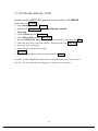
1
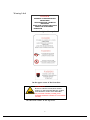
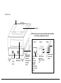
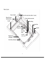
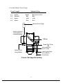
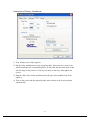
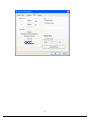
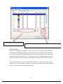
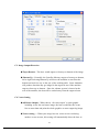
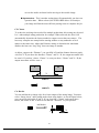
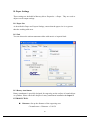
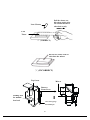
USER MANUAL
MERCURY
Content
QUICK MENU ............................................................................. 3
I. INTRODUCTION........................................................................ 5
Principles of CO2 Laser ..................................................................5
Safety ............................................................................................5
Precaution......................................................................................5
Fire Precaution...............................................................................7
Important Operational Notice for 50 W laser....................................7
Warning Label................................................................................8
Frequently Asked Questions............................................................9
Lens and Manual Focus Gauge......................................................14
Instruction of Rotary Attachment...................................................15
TOP VIEW...................................................................................16
Operation:....................................................................................16
SIDE VIEW .................................................................................17
Dual Head Installation ..................................................................18
II. RECOMMENDED CONFIGURATION ...............................21
Computer.....................................................................................21
Scanner........................................................................................21
Software.......................................................................................21
III. HARDWARE INSTALLATION ...........................................22
Cabling Connection:.....................................................................22
Parallel Transmission....................................................................22
Serial Transmission ......................................................................23
Interface for Macintosh.................................................................23
Exhaust Ventilation.......................................................................23
IV. SOFTWARE INSTALLATION .............................................24
Install LaserPro MERCURY printer driver ....................................24
V. OPERATION.............................................................................25
Environment ................................................................................25
Flexible Utility of Your Memory Buffer.........................................25
1
Am I in Multiple File mode or Single File mode now?...................26
Start to Operate ............................................................................27
START/STOP...............................................................................28
FUNCTION.................................................................................33
Software Operation.......................................................................45
VI. BASIC MAINTENANCE ......................................................68
Clean the mirror – Please refer to the figure as below.....................68
Clean the focus lens –...................................................................70
VII. TROUBLE SHOOTING.......................................................71
Quality Problems..........................................................................71
Non-operational Problems ............................................................71
Appendix A. 3D Function .............................................................72
Tip for 3D Application..................................................................72
APPENDIX B. Application Parameters ......................................74
Engraving Parameter ....................................................................74
Cutting Parameters .......................................................................75
APPENDIX C. Specification........................................................77
Optional Items:.............................................................................77
2
QUICK MENU
1.
2.
3.
4.
5.
Connect air exhaust system.
Setup computer and connect with engraving system properly.
Turn ON host computer system.
Install the MERCURY Driver. (for the first time use only)
Use Windows-based program (such as CorelDRAW, PhotoShop, PhotoPaint,
Illustrator, CASmate, Signlab, EasySign, AutoCAD, etc.) to operate with the
engraver.
Turn ON engraver. The lens carriage moves to the home position (upper left
corner) and the working table moves down 50mm approximately after system
initialization. (If a rotary attachment has been installed, the working table will
move down to the bottom.)
Auto-focusing: under STOP status, put work-piece on the table, move X-axis
(Please refer to Fig. 3) and carriage by arrow keys to locate the lens carriage
above the engraving material (holding carriage by hands for prompt moving is
acceptable under STOP condition but not recommended). Press
AUTO FOCUS the table will move upward and stop at the focal position
automatically.
The following is an example by using CorelDRAW V.11.
Layout
Page Setup
Set from Printer, choose Portrait
OK
Edit desired file (picture etc.)
File
Print
Properties
Options, choose desired Mode (refer to Fig. 11) then
set up proper resolution, power and speed
OK
Print
File name is shown on LCD then press START.
(Please refer to page 20, Start to Operate, for detail operation in different
mode selectio n)
6.
7.
8.
NOTE:
l
l
l
l
If the memory buffer is set up in Single file / No Repeat mode, under
START condition,
the engraver will start to engrave/cut upon receiving a file. While if the
memory buffer is set up in Multiple File mode, receiving at least one
complete file then press START to start a job (refer to page 20, Start to
Operate).
Choices of DPI must be the same for both editing and printing out a file.
Turn on the air exhausting system before engraving.
The maximum loading weight of working table is 20 kg.
3
NOTICE:
1. In order to match Mercury driver’s color. Make sure your CorelDRAW V.9.0 or
later the ‘Calibrate colors for display ‘ is disable. Please fallow the steps:
Tools
Options
Global
Disable ‘Calibrate colors for display ‘
Color Management
OK.
2. When operating with CorelDRAW V.9.0 or later version, please choose
Landscape for Page Setup when X > Y ; choose Portrait when X < Y
OK.
3. When using the available artworks from the Clipart of CorelDRAW, to prevent
the hidden vector lines shown on your engravings. Please do as follows:
CorelDRAW, choose file from Clipart
Bitmaps
Convert to
Bitmap
Click Color then choose Grayscale
OK.
4
I. INTRODUCTION
Principles of CO2 Laser
LASER is a Light Amplification by Stimulated E mission of Radiation.
A CO2 laser works by exciting the molecules of a carbon dioxide gas mixture.
To engrave, the beam is focused through a lens. The intensive beam can vaporize
the surface of the material leaving an engraved image or, in some cases, cutting
through the material.
Safety
The safety rating of Class 1 by CDRH means that the laser beam is enclosed in a
cabinet and has safety interlock mechanisms to protect the operator from
injury. While when a class 1 laser system equipped with a red dot pointer which
allows you to position laser beam, the safety rating turns into Class 3a due to the red
beam is laser light. A few extra safety precautions; namely, avoid placing your eyes
in the red beam path, is required.
Precaution
1. Always wear certified safety goggles. Reflective materials such as mirrors,
enameled brass and anodized aluminum may reflect a portion of the invisible
laser radiation. This may cause sever eye damage if appropriate safety
goggles are not worn.
NOTE: Each LaserPro laser machine is equipped with a safety goggle, if you
need another one, please contact LaserPro for it or try to get one that meets
the following specification.
190-398 nm OD5+
10,600 nm OD5+
Visible light transmission: 92.9%
2. Do not attempt to modify or disassemble the laser system at any time.
3. Wear appropriate safety goggles especially when engraving with mirrors or
coated metals such as enameled brass and anodized aluminum..
4. Good ventilation is required to remove odors and vaporized materials to the
outside of the building or structure. An exhausted system is recommended.
5
5. Do not work with reflective metals, heat sensitive surfaces or other materials
that may produce toxic substances, such as PVC and Teflon.
6. A fire extinguisher should be available on hand at any time.
7. Never leave the machine unattended during operation.
8. Follow the recommendations for maintaining and cleaning your system. Not
only will this enable you to engrave efficiently, it will ensure that your machine
runs safely as well.
6
Fire Precaution
1.When cutting materials that easily caught on fire, such as acrylic, wood or
paper, it is advised to have air compressor turned on to prevent flame.
2.If cutting table, or honey comb table, is used for cutting purpose, do not leave
any material underneath, as when material at top is cut through, the material at
below will be burned easily due to trapped heat.
3.It is not encouraged leaving the cutting job unattended, especially with
materials mentioned above.
Important Operational Notice for 50 W laser
18-20℃ is recommended temperature for 50W laser.If the temperature is too
high, the laser will be overheated and not functioning efficiently, or even shut
down. However, there is exception condition when the dew point (Ref.1, a
ratio between room temperature and humidity, it is the point when condensation
will form), is above 20℃.
On the other hand, if the temperature is too low, lower than the dew point, the
optic, including turning optic and output coupler, and electronic components,
such as RF and control board inside the laser tube will be damaged easily, due to
condensation form on them. When condensation form on the optic and when
laser beam hits the water, the coating of the optic will be damaged. And more
seriously, water on the optic will collect dust and dirt, which will lead laser to
burn and destroy the optic.
Therefore, to prevent such thing happening, the temperature of cooling water
MUST be kept above the dew point. If the room temperature is 20℃, and the
dew point is 18℃, the cooling water must be set at 19℃ or higher. If the dew
point is 22℃, which is higher than the highest recommended temperature for
operation, then the cooling must be set above 22℃. There may be some slight
degradation in the performance of the laser, but condensation will not form on
the tube or the electronics (Ref.2). Thus, it is recommended to install a
dehumidifier or air conditioner in the room where laser is in operation to prevent
humidity.
7
Warning Label
DANGER
INVISIBLE LASER RADIATION
WHEN OPEN
AND INTERLOCK FAILED OR
DEFEATED
AVOID EYE OR SKIN EXPOSURE
DIRECT OR SCATTERED
RADIATION
On the right of the top door
On the upper center of the front door.
WARNING!!
Do not use reflective metals, heat sensitive
surfaces or other materials that may produce
toxic substances, such as PVC and Teflon.
Any corrosion caused by working on an
unsuitable substances will not be covered in the
warranty.
On the front center of the top area.
8
CAUTION
AVOID PLACING YOUR EYES IN
THE RED BEAM PATH
On the fro nt center of the top door.
On the surface of Focus Carriage
Frequently Asked Questions
1. What materials can be processed by CO 2 laser?
Virtually any materials such as acrylic, wood, fabrics, glass, leather, marble,
stone, rubber stamps, paper products, coated metals, plastics (especially micro
plastic developed by IPI, Spectrum and Rowmark etc.) other hard-surface
materials blended with polyester and fibers ( Corian™ , Fountainhead™ , and
Avonite™ etc.) or laserable simulated products of stone, wood and metal etc.
Bare metals can not get a good engraving result by using CO2 laser. However,
special kind of spray has been developed that allows CO2 laser to mark on the
bare metals such as stainless steel, aluminum etc. Do not engrave or cut
materials which are heat sensitive or toxic substances can be produced ( e.g.
PVC and Teflon coating ).
2. What is the life cycle of the laser source?
The life cycle of laser source is around 20,000 hours, however it can be re-filled
and should be done by your dealer.
3. What is the main purpose of air assist system?
The air assist system can provide a much better engraving & cutting effect, as it
will blow away vaporized particles and prevent fire due to overheating.
9
4. What does cutting table do?
The cutting table, also kno wn as honeycomb table, is especially useful for vector
cutting application. The space between materials and working table, gapped by
cutting table, allows heat and smoke to be disbursed and vented out which may
otherwise cause bad cutting effect.
5. What is the maximum engraving speed of LaserPro Mercury?
The maximum engraving speed of LasePro Mercury is 1066 mm/sec (42
inch/sec). When engraving an A4 (18 x 28 cm) size square with 250dpi at full
speed, it takes LaserPro Mercury about 18 minutes to complete.
6. How to engrave an extremely long working piece?
The back door (or panel) of LaserPro Mercury can be removed by taking away
the screws. For a better ventilation and safe purpose, this special design is to
prevent the back door being opened without notice during operating. However,
you have to use magnetic devices to short the connector of the magnetic
switches on both side of the front door while opening for engraving extremely
long work-piece. When doing so, make sure that you wear safety goggles to
operate the machine.
10
Front View
Top Door
Switches & Ports
Control Panel
-7Laser Source
Front
Air Flow
Valve
Adjuster
Air Flow
Fixer
Press the ring to
pull out the air
tube.
Air inlet
connect to air
compressor
Turn clockwise to decrease
the air flow and
counterclockwise to
increase the air flow.
Please avoid turn off.
11
Back View
Top Door
NOTE: Please refer to Fig. 25 and follow the instruction
for the basic maintenance of mirror.
Step 3
Laser
source
inside
Back Panel
(Back Door)
Disassemble
to maintain
#1 mirror.
Please refer to
the right
layout.
12
Unscrew and
pull out
#1 mirror
carefully
without
touching the
surface of the
mirror.
Step 2
Unscrew and
remove the
dust prevention
box.
Step 1
Unscrew and
remove the
panel.
Motion System
Mirror 3 & Holder
Dust Prevention Box (Mirror 2 inside)
Release the Screw to
Pull Out the Mirror
Mirror 4 and Focus Lens inside
Y-axis Belt
X-axis Bearing
X-axis Motor
X-axis Belt
Bearing Track
Y-axis Belt
Manual
Focus Gauge
Holder
Focal -Sharp™
Magnetic Sensor
for Dual Head
Auto-focus Gauge
Port for Rotary Attachment
13
Lens and Manual Focus Gauge
Focal Length
1.5”
2.0”
2.5”
4.0”
Matched Color
LENS
Purple
Blue
Gold
Red
Option
Standard
Option
Option
MANUAL FOCUS GAUGE
Blue (same as 2.0”)
Blue
Gold
Red
Manual Focus Gauge
Insert to the hole
of the holder for
manual focusing
Mirror
Lens 2.0, 2.5 or
4.0
Slot position for
Lens 1.5 only
Manual Focus
Gauge Holder
Auto Focus Gauge
Focal-Sharp™
Focus Probe
Focus Carriage Assembly
14
Instruction of Rotary Attachment
1) Turn off the power of the engraver.
2) Put the rotary attachment onto the engraving table. Ensure the two screw holes
should match the two corresponding holes on the table and the white mark of the
left side align to the position of 24cm (9.45 inch) on the ruler, then tighten the
screws.
3) Plug the cable of the rotary attachment into the port in the middle front of the
engraver.
4) Turn on the power and the engraving table moves down to the lowest position
automatically.
15
TOP VIEW
ruler
track
White Mark
lever
port
Screw
Holes
Top
Window
Operation:
NOTE: The maximum length of the engraving object is 450 mm (17.71 inch).
The maximum diameter of the padded rubber wheel is 94 mm. To get an accurate
engraving position during rotating, it is better that the diameter of the engraving
object is not smaller than 90mm (3.54 inch). However, the maximum diameter of the
loaded object is 180mm and the limited loading weight is 7 Kg (15.4 Lb.).
1. Measure the diameter of the engraving area for setting up the software operation
(refer to Software Operation, Fig.20) before engraving.
2. Lift the lever, loading the engraving object, slide the adjustable end to the bottom
of the object firmly, then lower the lever of the fixture to secure it in place shown
as in Fig II.
3. If the engraved object is too small, please use 4- inch lens to prevent collision
between carriage and rotary attachment devise.
16
SIDE VIEW
Adjustable end
motor
lever
Base of the
padded
rubber
wheel
Open end of the engraving object
O
4. Turn on the power. The rotary attachment is detected and the working table moves
down to the bottom automatically. The system initializes to the home position, at
the same time.
5. Set up focus.
6. The following is an example of engraving process by using CorelDRAW V.8.0 or
higher version
File
Print Setup, choose LaserPro MERCURY then click
Properties
Paper, click Rotary Fixture , key in Diameter and Offset
value etc. then choose Lands cape
key in X value
OK
NOTICE:
When doing the Print Setup under print driver setting, please always
choose Landscape , no matter operating with CorelDRAW V.7.0, or higher
version or what the X and Y values are.
Layout
Page Setup
Set from Printer, choose
Landscape when X > Y; choose Portrait when X < Y
OK
NOTICE:
Please always choose Portrait for Page Setup on CorelDRAW V.7.0 no matter
X or Y value whichever is lager.
File
OK
Print
Properties, set up desired power, speed etc.
Define engraving location by moving the arrow keys and the red point will show
17
the right position you want. Moving the red point from rotary home position (at
the base of the padded rubber wheel) to the open end of the engraving object, the
Offset value (refer to Fig. II & Software Operation, Fig.20) will be displayed on
LCD.
Caution:
l
l
Adjust the working table and set up the focus under STOP status.
Set up focus after initializing the system to prevent the carriage hit the
engraving object.
Dual Head Installation
Step 1:Turn off the system.
Step2:Put the dual head carriage onto the X-axis belt bearing track.
Step3:Cut 25mm (1 inch) off the air assist tube on the original lens carriage.
Step4:Connect the air assist tube of the dual head with that of original carriage
by “T” connector.
18
“T“
Connector
Metal
Frame
Step5:Screw the metal frame which is attached to the right side of dual head to
the original lens carriage.
Step6:Turn on the power to test whether the dual head is installed properly.
During initiation, the system will detect the dual head carriage when it
moves the lens carriage to front-right side, so it would not crash the dual
head carriage when move the origin position.
Note:
1. Keep the screws on the lens carriage after taking off the dual head.
2. Put the black cap on the “T” connector after taking off the dual head to prevent air
flowing leaking.
3. Please choose dual head item from Paper option of printer properties before
outputting a graph with dual head carriage.
19
20
II. RECOMMENDED CONFIGURATION
Computer
Your PC must be sufficient to equip with Window 95 at least.
We recommend the specification of PC for better work as
below:
CPU
Pentium at least
DRAM
32 MB RAM or up
FDD
One 3.5" 1.44 MB floppy
HDD
1.2 GB Hard Drive or up
SVGA
15" Super VGA Monitor
★ ★On Board Parallel Mode(Setup from PC BIOS):
SPP— Preferred Mode
ECP— Cable length less than 1.8meters
Scanner
Flat Bed
Minimum resolution: 200 DPI
Software
GCC driver (designed under Window 95 or higher level)
Windows
Window 95 or higher
CorelDRAW
Version 7.0 or higher version
Any program that can output HPGL commands
21
III. HARDWARE INSTALLATION
Caution:
l
l
Turn all equipment off before making any connection.
Check the plug of the power cord to see if it matches the wall outlet. If not, please
contact your dealer.
Cabling Connection:
1. Insert the power cord (male) into a grounded power outlet.
2. Plug the other end (female) into the engraver. The engraver has been design to
switch from 100 ~ 240 VAC automatically (100W engraver has to use 220~240
VAC only).
3. The engraver can communicate with a computer through either a serial (RS-232C)
or a parallel port (Centronics).
Power on/off
Switch
15 AMP
resetable fuse
3 AMP
resetable fuse
AC Power
Connector
Serial Interface Connector
Parallel
Interface
Connector
Parallel Transmission
Connect a parallel cable to the engraver (parallel port) then to the parallel port of the
22
host computer.
Caution:
Never use a mechanical switch box when a second printer port is required.
The electrical surges can cause damage to the computer and the engraver.
Serial Transmission
If you are using IBM PC, PS/2 or their compatibles, connect the supplied
RS-232C cable to the engraver (serial port) then to the serial port of the host
computer.
Interface for Macintosh
To operate the engraver with a Macintosh computer (e.g. Power Mac), you
need a MAC modem cable (DIN8 to DB25) as an adaptor to connect to the
RS-232C cable.
Exhaust Ventilation
Exhaust
Blower
Air
Outlet
Connect to an air
filter or exhaust
air outside of the
building
Seal
Clip
23
4 inch diameter
flexible hose
IV. SOFTWARE INSTALLATION
Install LaserPro MERCURY printer driver for windows XP/ 2000/98
Power On, click START
? choose Settings and click Printers
? Double click Add printer and start Add printer wizard
? Next step
? Choose Local and click Next step
? choose Have disk and click Next step
? Insert the MERCURY Driver disk properly into the floppy drive then click OK
? choose the port where your laser system is connected and click Next step
?
?
?
?
name your system or bypass
choose the driver to be default printer
Next step
select No when asked to print a test page and click Finish
Now the LaserPro MERCURY printer driver is installed completely. Don't forget to
take the GCC driver disk from the floppy drive and store in a safe place.
24
V. OPERATION
Environment
l
l
l
l
A clean, well- ventilated room with a temperature of 15℃~ 25℃ (60℉~78℉)
(Strongly suggested the temperature of 25℃) and a relative humidity between
30% and 40%, as an office type environment.
Avoid from unstable voltage supply.
Short path for an effective air exhaust.
Have a fire extinguisher available at any time.
Flexible Utility of Your Memory Buffer
The standard memory buffer size of Mercury is 16M and can be expanded to 64M
( 32M SIMM x 2).
You can choose Multiple file mode with limited memory to save files and re-call
them for constant applications. Or, you can choose Single file mode to get an
unlimited data output while still keep files that you saved before under multiple file
conditions. However, the file sent under Single file mode will not be saved. In other
words, every time you want to engrave this file, you have to re-send again from the
host computer.
25
Am I in Multiple File mode or Single File mode now?
Power ON
LaserPro MERCURY
Firmware V x. xx
Copyright 200x
Initializing
Please wait
Table moves down
about 50mm.
Press FUNCTION key.
Set memory buffer?
Yes: ENTER
End operation: ESC
Z init/AF position?
Press ENTER key
Single / 1 File
Ok: ENTER
Change: △ or ▽
Multiple /100 Files **
Ok: ENTER
Change: △ or ▽
Single /No Repeat
Ok: ENTER
Change: △ or ▽
NOTE:
1. ** means default or current setting.
2. AUTO FOCUS and all other function keys should be operated under
STOP condition.
3. NEXT FILE and DELETE keys are invalid under Single file mode.
26
Start to Operate
Power ON
LaserPro MERCURY
Firmware V x. xx
Copyright 200x
Initializing
Please wait
Table moves down about 50mm automatically
Single file status
Under STARTcondition
Upon the receipt of files, start to
engrave/cut
File:
Speed:
Power:
DPI:
Multiple file status
Under STOP
condition
%
%
Copies
File:
Speed:
Power:
DPI:
Press START/STOP,
turn to STOP condition
File: # x
file name
Speed: xx.x % 00:00
Power: xx % PPI: xxxx
DPI:
xxx
xxx K
Press
START/STOP
to engrave/cut
%
%
00:00
STOP
Press
Press
Send a new file
FUNCTION
NEXT FILE
from host computer
key for further
to get a desired
then press
setting
file
NEXT FILE
selection
to show the file name
on LCD.
.
File: # x
file name
Speed: xx.x %
00:00
Power: xx % PPI: xxxx
DPI:
xxx
xxx K
27
START/STOP
l Single File Mode:
Turn on power, MERCURY is under START condition and ready to receive a file.
LCD shows as follows:
File:
Speed:
Power:
DPI:
%
%
Copies
1
Upon the receipt of a file, MERCURY starts to engrave/cut immediately. When a job
is done, LCD will show the working time such as 01:10 means 1minute and 10
seconds.
File:
file name
Speed: xx
%
01:10
Power: xx
%
STOP
DPI: xxx
Press START/STOP key, turn the engraver to STOP condition. LCD shows as
follows. Under STOP condition AUTO FOCUS and all other function keys can be
operated while NEXT FILE and DELETE keys are invalid under Single file mode.
File:
Speed:
Power:
DPI:
file name
% 00:00
%
STOP
28
l Multiple File Mode:
Turn on power, Mercury is under STOP condition and all function keys can be
operated. Laser engraver is ready to receive a file. LCD shows as follows.
File:
Speed:
Power:
DPI:
%
%
00:00
STOP
Upon the receipt of a complete file, LCD will show the following message for
instance. Then press START/STOP key, the engraver starts engraving or cutting.
File: # 1
file name
Speed: 70 %
00:00
Power: 40 % PPI: xxxx
DPI:
500
If there is no file having been sent, the message will display as follows.
Wait until at least one
complete file is
received, then press START
NOTE: Please refer to the flow chart of “Start to Operate”, page 20 .
ENTER
Accept and store the selection for setting up.
AUTO FOCUS
This key can only be operated under STOP condition. Press this key will move up the
working table until the engraving object touches the tip of the focus tool, then the
table will move down and stop in focus automatically.
Whenever you change a lens with different focal length, press Function key and go
through the process of “Select lens ” . After changing the lens, press AUTO FOCUS
key to save the new focal length in memory. LCD will show as follows:
Focusing
Then do setup or send a file
to start a job
0.0 mm
NOTE: 1. “0.0 mm” means the focus position is the Z-axis home position of the
29
Working table. Above this position the value is negative while below this
position the value is positive.
2.Whenever the motion system or working table has ever been adjusted by
a technical person, please press AUTO FOCUS key to get an initial
position before going through the function of “Tuning” (Auto focusing)
to change the focal length.
NOTICE:
To stop the motion of auto focus, please press either UP or DOWN arrow key. If
you press the key continuously, working table will move up or down
correspondingly.
Arrow Keys
Move cursor on the display for selection or adjust the working table on Z position by
pressing the arrow keys of UP and DOWN.
NOTE:
UP key – After initializing, press this key will move up the table. LCD
displays:
Focusing
Then do setup or send a file
to start a job
-X.X mm
During working time (i.e. Start condition), this message won’t be shown.
When Auto Focus is under process, press UP key will stop t he motion of
Auto Focus and change to up movement.
DOWN key – Same as above function but the motion direction is opposite.
ESC (Escape)
Exit and back to the main menu.
NEXT FILE
This key is valid under Multiple file mode only. Press this key the LCD shows
File: # x
Speed: xx
Power: xx
DPI: xxx
file name
%
00:00
% PPI: xxxx
xxxxx k
The “k” message shows on the lower right corner expresses the k bytes memory that
30
has been left over in the buffer.
PPI means pulse per inch.
File: # shows the current working file number. Press NEXT FILE each time will
increase 1 (i.e. 1, 2, 3… 100) and recycle the counting. Once the buffer has received
up to 100 files, the LCD shows:
More than 100 files
are not allowed
Please delete files
then other files
If a file received is out of memory, the LCD shows
Not a complete file
due to out of memory
Please delete some
and send again
RED BEAM
On/Off red beam
SPEED
Set up laser speed for desired effect. When working without using MERCURY’s
driver, lower case press FUNCTION key then select one of the sixteen setups then set
up desired cutting speed. No matter you are using MERCURY’s driver or not, you can
change speed on the fly by pressing PAUSE key prior to change speed during cutting
or engraving. Set up desired speed, press ENTER then press RESUME to continue
the job.
POWER
Set up laser power for desired depth and effect. Other conditions are same as stated in
SPEED.
PAUSE
Temporarily stop the job during cutting or engraving.
RESUME
Continue the temporarily stopped job.
31
DEL FILE
This key (delete file) is valid under Multiple file mode only.
Delete current file?
Sure: press again
No: ESC
Press DEL FILE again to delete the file and LCD shows
Now deleting current
file please wait
32
FUNCTION
l Set memory buffer?
Setting memory buffer in Single file mode when working with a large data file, or
Multiple file mode (up to 100 files) that can be saved for constant engraving.
Under Single file mode, you can only output one job a time. Unlimited data can be
transferred without saving in the buffer therefore once you want to repeat the job you
have to re-send the file from the host computer.
Under Multiple file mode, you can engrave one job while transfer and design the next
simultaneously until reaching 100 files’ limit, or memory is used up.
Press FUNCTION key
Set memory buffer?
Yes: ENTER
End operation: ESC
Z init/AF position? :
Press ENTER key
Multiple /100 Files **
Ok: ENTER
Change: △ or ▽
△ or ▽
Single / 1 File
Ok: ENTER
Change: △ or ▽
Single /No Repeat
Ok: ENTER
Change: △ or ▽
ENTER
Z init/AF position?
Yes: ENTER
End operation: ESC
Delete all files ?:
33
l Z init/AF position?
To avoid focus carriage hitting the engraving object accidentally during initializing,
working table will move down about 50mm automatically after power on the
equipment. Whereas, if a rotary attachment has been installed, the working table will
move down to the bottom of the engraver.
After initializing as long as you have not pressed AUTO FOCUS key, you can go into
this function and move the working table back to the power on position. Once the
AUTO FOCUS key has been used, the last auto focus position has been saved in the
memory. Therefore, the table will move to the last auto focus position by using this
function.
Z init/AF position?
Yes: ENTER
End operation: ESC
Delete all files? :
Table is moving to
init or AF position
End operation: ESC
Delete all files? :
ENTER
Delete all files?
Ok: ENTER
End operation: ESC
Select lens? :
34
l Delete all files?
All files in the buffer will be deleted by using this function when setting under
Multiple file mode.
This function is invalid under Single file mode. Once you stop or complete a job
under Single File mode the file won’t be saved in the buffer.
Delete all files?
Ok: ENTER
End operation: ESC
Select lens? :
ENTER
Are you sure?
Sure: ENTER
No: ESC
ENTER
Select lens?
Yes: ENTER
End operation: ESC
Select unit? :
35
l Select lens?
There are four different lenses for use on the LaserPro MERCURY as follows:
Focal Length
Resolution
Cutting capability
1.5”
optional
High
Thin
2.0”
standard
2.5”
optional
Low
Thick
4.0”
optional
The high resolution lens is designed for precision engraving, while the low resolution
lens is mostly applied for cutting due to its lower beam divergence which results in a
straighter cut in thick materials.
The longer the focal length, the bigger the beam spot size. Although it is not ideal for
high resolution image engraving. The large spot size of low resolution lens can
spreads the laser’s heat over a larger area, which helps minimizing melting thus can
be applied to engrave certain kinds of plastics.
Select les?
Yes: ENTER
End operation: ESC
Select unit? :
ENTER
2.0 inch (50.8mm)**
Ok: ENTER
Change: △ or ▽
△ or ▽
x.x inch (xx.xmm)**
Ok: ENTER
Change: △ or ▽
Replace lens of
1.5 inch
2.5 inch
4.0 inch
After changing lens, press
AUTO FOCUS and the new
focal length will be saved
automatically.
Select unit?
Yes: ENTER
End operation: ESC
Set EOF alarm? :
36
l Set power ramp?
If set in Enable condition and cutting speed is 3% or above, under vector mode, the
power control is enabled. If set in Disable, the power control is disabled.
Default : Enable
Set power ramp?
Yes: ENTER
End operation: ESC
Select unit? :
ENTER
Enable **
Ok: ENTER
Change: △ or ▽
Change: △ or ▽
Disable
Ok: ENTER
Change: △ or ▽
ENTER
Select unit?
Yes: ENTER
End operation: ESC
Set EOF alarm? :
37
l Select unit?
Set unit in Metric or English.
Select unit?
Yes: ENTER
End operation: ESC
Set EOF alarm? :
ENTER
Metric (mm)**
Ok: ENTER
Change: △ or ▽
△ or ▽
English (inch)
Ok: ENTER
Change: △ or ▽
ENTER
Set EOF alarm?
Yes: ENTER
End operation: ESC
Tune Autofocusing? :
NOTE: ** means default or current setting.
38
l Set EOF alarm?
If set in Enable condition, a beep tone sounds when End OF File.
Set EOF alarm?
Yes: ENTER
End operation: ESC
Tune Autofocusing? :
ENTER
Enable**
Ok: ENTER
Change: △ or ▽
Change: △ or ▽
Disable
Ok: ENTER
Change: △ or ▽
ENTER
Tune (Autofocusing)?
Yes: ENTER
End operation: ESC
Select setup #1-16? :
39
l Tune (Auto focusing)?
In case the focal length of auto Focus needs to be corrected, please insert the
corresponding manual focal tool to the hole of the holder shown as in the Figure of
LENS and MANUAL FOCUS GAUGE. Then, operate as follows.
Tune (Autofocusing)?
Yes: ENTER
End operation: ESC
Select setup #1-16? :
If you have ever pressed
AUTO FOCUS after
power ON
ENTER
If you have not pressed
AUTO FOCUS after
power ON
Press AUTO FOCUS key
then FUNCTION key
select the function
Tune (Autofocusing)
Press arrow up/down key to
tune focusing position then
press ENTER
Attach manual focus gauge to
the carriage and press arrow key
up and down to position the
working table in focus then press
ENTER.
New focal length has been
saved.
Complete tuning
Ready to setup or
send a file to
start a job
Select set up #1-16?
Yes: ENTER
End operation: ESC
Select baud rate? :
40
l Select setup #1-16?
You can assign 16 different colors individually for speed and power to achieve a
variety of cutting effects. This function works when your software package can
output HPGL plot without us ing MERCURY’s driver.
Select setup #1-16?
Yes: ENTER
End operation: ESC
Select baud rate? :
ENTER
Setup # 1
**
+: △
-: ▽
Ok: ENTER
End operation: ESC
Change: △ or ▽
Setup # x
+: △
-: ▽
Ok: ENTER
End operation: ESC
ENTER
Set Speed and Power first without
operating through Driver
Select baud rate?
Yes: ENTER
End operation: ESC
Data bit/parity? :
Press POWER key to change
Power
Press SPEED key to
change speed
SPEED: x x . x %
+: △
-: ▽
End operation: ESC
POWER: x x x %
+: △
-: ▽
End operation: ESC
ENTER
ENTER
Save the desired cutting power
for not using Mercury’s driver
Save the desired cutting speed
for not using Mercury’s driver
NOTE: ** means default or current setting.
41
l Select baud rate?
Baud rate is to determine the speed of data transmission of serial port to communicate
with the host computer.
Setting range: 9600, 19200, 38400, 57600
Defaults: 57600
Select baud rate?
Yes: ENTER
End operation: ESC
Data bit/parity? :
ENTER
57600 bps
**
Ok: ENTER
Change: △ or ▽
△ or ▽
xxxxxx
bps
Ok: ENTER
Change: △ or ▽
ENTER
Set data bit/parity?
Yes: ENTER
End operation: ESC
Select language? :
NOTE: ** means default or current setting.
42
l Set data bit/parity?
Data bits refer to the size of one block of data and parity is used to check if data was
received correctly or not. The data/parity feature is to adjust the byte format and
parity type in order to communicate with the host computer through serial port.
Set data bit/parity?
Yes: ENTER
End operation: ESC
Select language? :
ENTER
8 bits no parity
Ok: ENTER
Change: △ or ▽
**
△ or ▽
8 bits even parity
Ok: ENTER
Change: △ or ▽
ENTER
Select language?
Yes: ENTER
End operation: ESC
43
l
Select language?
Select language?
Yes: ENTER
End operation: ESC
ENTER
English
**
Ok: ENTER
Change: △ or ▽
△ or ▽
xxxxxx
Ok: ENTER
Change: △ or ▽
English
Italian
Deutsch
ENTER or ESC
Single file mode
Multi file mode
Do setup or press
STAR key then send
only one file
Do setup or send
at least one file
then NEXT FILE
key select a file
NOTE: ** means default or current setting.
44
Polish
Japanese
Turkish
Software Operation
Editing Jobs
A. CorelDRAW Page Size Setting
Please ensure the laser engraver is set as the Default Printer before following the next
steps.
Step1: Click Layout
Page Setup
Step2: Get into Document
Page
Size
Step3: Click Set From Printer to resize the page size to be the same as the printer’s
paper size.
(Ensure the Normal Paper and Landscape options are checked.)
Step4: Click OK to complete the page size setting.
Notice
Pre: In some instances, the LCD panel shows a message of “Graph was clipped” or the
laser engraver is engraving at some strange location in some unpredictable way. The
result engraved artwork is scrapped.
Post: This is caused by the mismatch of Printer’s paper size and the CorelDraw’s page
size. To matches these two size, please following the proceeding instructions.
45
Step5: Check the Page Size has changed
46
B. Vector Cutting
The laser cutting is NOT doing a proper cutting, because the width of the text’s
outline is not set to its thinnest width. The MS-Windows® driver determines raster
engraving or vector cutting based on the outline width of an object. Therefore to
achieve a vector cutting, please set the text’s filled with white color and the outline to
its thinnest width in CorelDraw.
How to perform vector cutting:
1. Select the text in which the change applies by clicking on the text
2. Change the text’s fill color to white by left clicking on the white color of
“CorelDraw Color Palette” located on the right hand side of the screen.
47
3. Change the text’s outline color by right clicking on the desired color on
CorelDraw Color Palette.
Notice
If the width of the line to be cut is not set at minimum value, the laser is
going to performing etching instead of vector cutting. The laser unit looks
like engraving from left to right and right to left instead of cutting.
48
4. Change the outline to its thinnest width by right clicking on the selected text
5. Go to the “Properties” option
6. Click on the “Outline” tab and change the “Width” to its thinnest dimension.
49
7. Click on “OK” to apply the changes.
8. Print out the selected text again and the laser will do the letter cutting.
C. Raster Engraving
Laser engraver prints raster as grids or dots of individually pixels, any digital or
scanned images can be processed by a laser engraver. When doing raster engraving,
the laser would move from left to right or right to left. After the image or graphics is
ready, please go further to the laser printing operation as next paragraph is shown.
50
Printing – Mercury Driver Editing
After completing the editing job, choose File
access Mercury driver parameter settings.
51
Print and click “Properties” to
A. Choose Printing Mode
A-1 B/W (Black & White) Mode
It is useful to activate this mode when using clip art or drawings with several colors,
shades of gray, or many outlines. This mode will create a laser output similar to that of
a laser printer. The entire selected image will be engraved using a single pen, black
one (power & speed setting). The Mercury driver will interpret colored and shaded
areas as different shades of gray / halftone areas, and it is a collection of dots. The
resolution and depth of these halftone areas can be adjusted with the DPI, the B/W
mode dithering settings from 2x2 to 8x8, error diffusion, and different pattern types
Experiment with these different settings to get the optimal results for your application.
52
n
Dithering type – The gray areas of image will be filled with different dot/
grid density from a 5- grade halftone with 2x2 dots to a 65- grade
halftone with 8x8 dots. 8x8 dithering type would presents the image into
shading effect with more dots than the 2x2 dithering, while the 2x2
dithering type would have smaller dots than 8x8, that produces higher
resolution. The dithering type choice would depend on the image and
application.
n
Enhance dithering – The enhance dithering as what it reads would help
to compensate the shortage of smaller grade halftone type, suc h as
choosing 2x2 dithering type and enhance dithering at the same time, the
image would be printed with 256- grade halftone and 2x2 dots, therefore,
better shading effect with small 2x2 dots/ grids.
n
Error Diffusion – The error diffusion presents the shade of image as a
spread halftone instead of dots, therefore more detailed.
n
Pattern Type- The halftone pattern has three kinds of layout options,
which determine the shape of each grid/ dot to compose the shading
effect of raster image.
a. Dot: A halftone pattern consists of circle dots.
b. Corner: The dark dot spread from the left upper corner of the pattern
53
result in a little triangle shape to imitate a shading effect.
c. Bayer : A random halftone pattern.
2*2 dithering
4*4 dithering
8*8 dithering
Error Diffusion
2x2 Enhance Dithering
8x8 Enhance Dithering
Dot
Bayer
Corner
A-2 Manual Color Fill Mode
Each power and speed setting can be linked to certain color on the layout. Totally 16
color settings are available. The desired color can be adjusted by changing the ratio of
Red, Green and Blue. If the speed or power is set to 0, the corresponding color area or
vector line will be invalid.
A-3 3D Mode
With this function, we can get the sculpture effect. The engrave image must have gray
levels. The engrave image is effected by PPI, DPI, power and speed setting.
54
3D Image File
Sample/ Material: Density Board
A-4 Stamp Mode
Mainly used in rubber stamp production. Create a slope base of stamp characters by
setting up the stamp parameter. Normally the pitch number for engraving a 2~3mm
thick rubber pad can be set at 0.2 or 0.3. The smaller the pitch number, the sharper the
slope. If setting the pitch number at a very big value, it may take for a very long time
for the math calculation.
n
Pitch Value & Shoulder Power Setting
The finished stamp will be a reversed image with engraved depressions
55
and ridges. Many of these ridges may be too thin and would break off or
be unstable. Creating pitch is a way to add support to the thin lines and
ridges. The pitch value setting allows you to adjust the width of the ridges.
Broad pitch gives the maximum amount of support for each ridge.
Experiment with different pitch value settings in order to produce the
stamp that is best suited for your application. You can specify the size into
the pitch box under stamp mode and adjust the bar to specify different
laser power level for shoulder.
The central part
presents the letter of
stamp.
The blue bar means different laser power level to compose of the slope. Higher
level blue bar gets less engraving laser power.
n
Power Level of Stamp Mode
This function is to adjust the power distribution of the slope shoulder to
get the better shape of stamp’s vertical profile. Select “set shoulder” in
the page “Options”. Enter the dialog box of stamp parameter. The black
bars in the center are for the surface of each letter, while the blue bars are
for the shoulders. Adjust the value of power level by adjusting bar or the
left click of mouse to edit the shape of the shoulders.
56
n
Add Border
You may wish to include a thin or wide border around the outline of your
stamp. This can be done by creating outline greater than .001” thickness
around the image. When the Mirror setting is selected, this outline will
automatically be reserved as a ridge that does get engraved.
n
Invert
The Invert mode will reverse the black and white outlines and fills in the
selected image. Black will become white and vice-versa, thus creating a
high area that will be covered with ink when the stamp is put to use. This
function is disabled when using the Manual Color Fill mode.
Invert
n
Mirror
When using a stamp, the image needs to be reversed or mirrored in order
to show up properly when the stamp is in use. This setting will transfer
57
right to left and vice-versa.
Mirror
n
Cutting out the Stamp
After you have created a border around the stamp, you may wish to have
the Mercury’s vector setting cut out the stamp from the rubber sheet. To
do this, create a thin (0.001”) red line around the outline edge of the
border or where ever you wish the stamp to be cut. The vector setting will
always be performed after the engraving is complete.
n
Stamp Production
You may wish to create a full sheet of duplicated rubber stamps in order
to have them all engraved at once, saving on material costs and operatio n
time. To do this, copy and paste the image to the full page which is
smaller or equivalent to the working table and the rubber sheet. Next
make sure that the image is mirrored, inverted and that the appropriate
shoulder, border, power and speed settings are in place.
B. Parameter Settings
The LaserPro Mercury allows the use of 16 different colors to represent 16 different
power and speed settings when cutting and engraving. These colors are referred to
as PENS. Try to think of each pen as a designated laser setting, rather than as a color.
An image that is only black and white will use only one power and speed laser setting
(Black). An image that includes black, red and blue colors will use three different
assigned power and speed settings. In order to utilize up to 16 different pens, make
sure your graphics program uses the 16 colors recognized by the driver.
58
Adjust speed / power for each pen
Check to enable or disable raster / vector / power ramp for each pen
B-1 Pen Settings
There are 16 available pen settings to match a specific laser setting with the different
colors used in the graphic image. If your image uses black outlines, and red and blue
color fills, then the driver will instruct the laser to use three different power and speed
settings on the three distinct areas. The speed and power settings designated to each
pen color, will represent a proportion of the master control speed and power settings.
If you would like to use a color not included in the driver’s original 16 colors, please
double click on the specified pen and the color manage r window would jump out then
you can select the color you would like to apply.
59
B-2 Speed
Speed setting here determines the speed of laser’s motion system during operation.
The range is from 0.1% ~ 100%. 100% speed is equivalent to the fastest speed and
will be the speed that the motion system travels when cutting or engraving straight
lines. The machine will automatically slow down when it is cutting or engraving
curves.
B-3 Power
Power setting here would decide the laser’s power during operation. The range is from
0.1% ~100%. The percentage represents the power of each laser pulse fired. Power
and speed work together to determine the depth of a cutting and/or engraving. Higher
power and slower speeds will produce the deepest engraving.
B-4 Raster Ve ctor On/Off
Each color in the graphic image may include a variety of color fills and very thin lines.
It is then possible for one pen color to require both raster and vector modes. Turning
either Raster or Vector off will force the driver to ignore the pen color’s fills or thin
lines. You can check the Raster or Vector box to turn on/ off the function.
60
B-5 DPI – Dots Per Inch
This setting determines the quality of image resolution was using the raster engraving.
DPI can also be referred to as horizontal lines per inch or fill spacing. The amount of
raster strokes per vertical inch of travel will affect the image resolution of the
engraving. Higher DPI settings will have cleaner and deeper engravings, but will take
longer to complete. Lower DPI settings will have coarser and shallower engraving,
but will take less time to complete. Experiment with different settings to get your
desired effect. You can find the DPI function at Mercury driver-> Properties-> Option.
B-6 PPI – Pulses Per Inch
This setting should not be confused with DPI. PPI determines the gross amount of
laser pulses there will be per linear inch. The adjusted range is from 30 to 1500 PPI or
you can choose auto mode. When choosing auto mode, the system will come up with
the proper PPI value automatically. In order to maintain the quality of raster graph, the
PPI value will at least equal to DPI value automatically even you set the lower PPI
value than DPI value. Low PPI settings are a good example of how the LaserPro
Mercury can perforate paper.
B-7 Save Parameters Setting
Each job may require unique Mercury driver parameter settings. After you have
adjusted all of the settings, remember to save it in a desired location for future use.
Press the SAVE icon and save the parameter settings to the proper directory as wished
or default for all applications, then you can see the saved files shown in the History
Files column. You can access your saved settings by clicking on Load or by using the
History scroll, which keeps track of the settings most recently used.
Note:
a. These editing options can be saved in image files such as CoreI Draw
graphics with printer driver parameters setting inside or can be saved a s
the default settings in Mercury driver for future files.
b. Please make sure your ID to log in the computer is set to “Administrator ”
level, therefore OS of 2000/XP can allow you to save parameter settings.
61
File parameter
setting save, delete
or load function.
Review and select the
saved file parameter
setting here.
NOTE: If you wish to use Border and Cluster, then the border must be less than
62
the distance specified in the Cluster setting.
C. Advance Setting
C-1 Scaling
Scaling function enables you to adjust output inaccuracy when you find the actual
output scale is different from what you set in the computer, you can use scaling
function to modify it and get a perfect one. Positive value is to enlarge the size,
negative is to reduce size. For examples, adjust the scale by +10 to enlarge the
object’s size by 10/1000.
C-2 Position mode options
n
Home: Focus carriage goes back to the upper right position after finishing a
job.
n
Without Home: Focus carriage stops at the last position of a data file. You
can engrave inside a bowel or a concave object to prevent hitting the object.
n
Relative Move: You can place the focus carriage at any place you want to
start a job. When finishing a job, the focus carriage will move back to the
starting point. You can engrave inside a bowel or a concave object to prevent
hitting the object.
63
C-3 Image Output Direction
n Top to Bottom – The laser would engraver from top to bottom of the image.
n Bottom Up – Normally, the LaserPro Mercury engraves from top to bottom,
left to right. Selecting Bottom Up will force the machine to start from the
bottom and work its way to the rear of the working table. Some laminates
will produce dust that may get lodged in the engraved area if the machine
engraves from top to bottom. Since the exhaust system is located at the
rear of the machine, the dust will be sucked away from the engraved area.
C-4 Vector Setting
n All Raster Output – When choose “all raster output” to print graphic
including vector line and raster image, the laser would take the vector
line as raster data and print the whole graphics as raster engraving image.
n Vector sorting — When your image has one vector cut area enclosing
another vector cut area, this setting will automatically direct the laser to
64
cut out the inside enclosure before moving to the outside image.
n Optimization – This is another setting that will automatically cut down on
operation time. When selected, the EXPLORER driver will analyze
your image and find the most efficient passing route to complete the job.
C-5 Cluster
To reduce the working time needed for multiple productions, this setting may be used.
Let’s take multiple stamp production for example. When selected, the driver will
automatically determine the fastest method to engrave more than one stamps. The
laser may complete one stamp before starting another or may undertake several
stamps at the same time. Adjust the Distance setting to determine the maximum
distance the laser can “leap- frog” from one image to another.
As below, suppose the “Distance” you specified is D and the distance between graph
A & B is X. If you chose the function “Cluster” and X > D, the output movement will
be route b. If you don’t chose “Cluster” or even you chose “Cluster” and X = D, the
output movement will be route a.
A
B
X
route a
route b
C-6 Border
You can add border at image edge for a better output of the stamp image. You must
select “Image Invert” under stamp mode when using border. As for the figure below,
you can specify the border X and Y. If you chose the “Cluster” and want to have
border, the border X and Y must be less than the “Distance” D you specified.
Add border
origin
Y
65
X
D. Paper Settings
These settings are included in Mercury driver Properties → Paper. They are used to
adjust several output settings.
D-1 Paper Size
As described in Paper and Layout Settings, ensure that the paper size is no greater
than the working table area.
D-2 Unit
You can choose the unit measurement either with metric or imperial inch.
D-3 Rotary Attachment
Rotary attachment is specially designed for engraving on the surface of round objects
or cylinders. Please check the chapter of rotary attachment installation in chapter I
INTRODUCTION.
n
Diameter: Set up the diameter of the engraving area.
Circumference = Diameter x 3.14159
66
n
Offset: The distance from the open end of the engraving object to the
base of the padded rubber disk. The offset value will be displayed on the
LCD screen.
D-4 Dual Head
When working with Dual Head, the function of Rotary Fixture is disabled and vice
versa. The working size for dual head is 305mm x 458mm, while enable the rotary
fixture the working size will change into 635mm x 458mm.
67
VI. BASIC MAINTENANCE
Caution:
l
l
l
Keeping the optics and motion system clean is essential to an excellent quality
engraving and the reliability of your engraver. Please clean Bearing track and
X-axis (DU) bearing daily to maintain good condition of machine.
Never pour or spray any liquid directly onto the laser system.
Turn off the power and unplug the system before cleaning.
1. Inside the System: Open the top door, the front door and the back door (if
necessary). Vacuum to clean inside of the engraver and vent area thoroughly.
2. Engraving Table: Dampen the paper towel or cloth with alcohol or cleaner to
clean the Engraving Table.
3. Motion System: Dampen the cotton swab to clean the rails of the Motion
System. Get rid off any debris built up in the bearing tracks.
4. Bearings: Hold a dampened cotton swab against the bearing and moving the
motion system by hand to clean each bearing.
5. Mirrors and Lens: The focus lens and the mirror located on the carriage are
the two components most likely to require frequent cleaning.
Caution:
Don't scratch out the soft coating of the mirror's surface. Excessive cleaning
the mirrors and lens may cause damage and reduce their life cycle (refer to
Fig. 24).
Clean the mirror – Please refer to the figure as below
1. Unscrew and remove front cover of the focus carriage. Release the
top screw and pull out mirror carefully.
2. Put lens tissue on the mirror and drop a little lens cleaner on the
middle area of the tissu, after the fluid has been absorbed evenly, pull
the tissue one direction gently to clean the mirror.
3. Let it air dry and re- install it.
4. Unscrew and remove the dust prevention box then clean the X-axis
Mirror, Y-axis Mirror and #1 mirror same as above process
separately.
68
Pull the tissue one
direction gently after
the cleaner has been
absorbed evenly
Lens Cleaner
Lens
Tissue
○ (CORRECT)
○ (CORRECT)
Do not use cotton swab to
rub clean the mirror
╳ (INCORRECT)
Top Screw
Mirror
Remove
Front Cover
Loading hole
for manual
focal tool
L
Auto-focus gauge
Focal -Sharp™
69
Clean the focus lens –
1. Unscrew and remove the front cover of the focus carriage. Pull out
focus lens carefully.
2. Flood the focus lens with lens cleanser on both sides then using a
cotton swab or lens tissue to dry off the remaining solution gently.
3. Do not touch the lens surface with your bare hands or press down
hard with any cleaning material.
70
VII. TROUBLE SHOOTING
Quality Problems
l
l
l
l
Check focus length set under the function key to see if it matches the type of the
lens installed.
Focus Lens is not installed correctly. Focus Lens is loose in the holder.
Debris or dust builds up in the bearing tracks or X-Axis rails.
The focus lens and the mirror in the carriage are damaged or need to be clean.
Non-operational Problems
l
Laser beam does not generate.
1. If the red alignment beam is not revealed, the laser beam is misalignment.
Adjust reflection mirrors for exact focus.
2. If the red alignment beam is revealed, please check the driver power. The laser
power may be too low to be detected. Please increase the percentage setting of
the Laser Power from the software driver or the control panel.
3. Please check if the laser power connector is loose.
4. For safety purpose, the laser beam will not be generated when the top or front
door is opened unless you short the connector of the magnetic switches.
5. Check water level or temperature of water cooler for 50W and 100W engraver.
If over-heated, laser beam will shut down automatically.
71
Appendix A. 3D Function
Tip for 3D Application
When doing 3D sample on LaserPro Mercury (L-25), acrylic or MDF wood are ideal
materials for the purpose. For acrylic the suggested PWR is 100%, SPD around
30%(depends on how deep you want to cut).
The perfect image for 3D is like those shown below. When image is ready, choose
3D Effect as the output mode in the driver. Sometimes, some material shows better
effect if you run the job with 2nd pass with laser out-of- focus. Especially with acrylic,
the 2nd pass will smooth out the surface.
For engraving wood, as it burns easily and leaves blackened surface after the 1st pass,
it is necessary to run the 2nd pass to remove the burned surface. To do that, simply
fill the image with black colour as the mask (see below) and Run the black mask
image with PWR 100% and SPD100%.
Create a black image
for polishing
72
3D engraving / Material: 1cm Acrylic
by Mercury 25W
Lens: 2 inch
Step Speed Power DPI PPI
Focus
Remarks
1
25%
100% 600 auto
Auto Focus
2
25%
100% 600 auto
3
100%
100% 600 800
4
0.2%
100% 500 auto Move table up 1.3mm
3D Mode Engraving
Lower down table 2.5mm 3D Mode Engraving
Lower table again 2 mm Black and White Mode Polishing
73
Cutting off
APPENDIX B. Application Parameters
Engraving Parameter
Material
LaserPro
Power%
Speed%
Acrylic
L-12
L-25
L-50
100
50
25
100
100
100
Laminated Acrylic
L-12
L-25
L-50
80
40
20
100
100
100
Immitation Leather
L-12
L-25
L-50
100
50
25
100
100
100
Leather
L-12
L-25
L-50
60
30
15
100
100
100
Mat Board
L-12
L-25
L-50
100
100
50
50
100
100
Padauk
L-12
L-25
L-50
100
100
85
30
60
100
Sign Vinyl
L-12
L-25
L-50
50
25
12
100
100
100
Rubber
L-12
L-25
L-50
100
100
100
8
15
30
Brass Coated
L-12
L-25
L-50
100
50
25
100
100
100
Glass
L-12
L-25
L-50
100
100
85
30
60
100
Crystal
L-12
L-25
L-50
100
100
85
30
60
100
74
Poly buttons
L-12
L-25
L-50
100
100
85
30
60
100
Marble
L-12
L-25
L-50
100
100
85
30
60
100
Ceramics
L-12
L-25
L-50
100
100
50
50
100
100
Cutting Parameters
Material
Acrylic
LaserPro
L-12
Power%
100
Speed%
1
L-25
100
2
L-50
L-12
100
100
4
0.4
L-25
100
1
L-50
L-12
100
100
2
0.4
L-25
100
0.8
L-50
L-12
100
100
1
0.2
L-25
100
0.4
L-50
L-25
100
100
1
0.2
L-50
100
0.4
12mm
L-25
L-50
100
100
0.2
0.4
Rubber
2.5mm
L-12
L-25
L-50
100
100
100
0.4
1
2
Backlite
1mm
L-12
L-25
L-50
100
100
100
0.2
0.4
1
Plywood
3mm
L-12
100
1
L-25
100
2
L-50
100
4
2mm
3mm
4mm
5mm
8mm
75
4mm
5mm
L-12
100
0.4
L-25
L-50
100
100
0.8
2
L-12
100
0.2
L-25
L-50
100
100
0.4
0.8
Be noticed that above parameters are for reference only. Various kinds of elements,
structures and component ratios may affect the engraving and cutting results
differently.
76
APPENDIX C. Specification
MERCURY
L-12
L-25
L-30 L-35
L-40
L-60
L-75
L-100 L-120
Laser Source
12W
25W
30W 35W
Air Cooled, Sealed CO2 laser
40W
60W
75W
100W 120W
Work Area
25” × 18” (635mm × 458mm)
Max. Working Piece
(all doors closed)
31.5” × 22.4” × 6.5” (800mm × 570mm × 165mm)
Max. Working Piece
(all doors open)
26.8”× 8 × 6.5” (680mm × 8 × 165mm)
Table Size
31” × 20.9” (790mm × 530mm)
Overall Dimensions
44.3” × 28.3” × 39.6” (1125mm × 720mm × 1005mm)
Drive
DC servo control
Speed Control
Adjustable from 0.1% to 100% of 42 inch/sec with up to 16 colors linked speed
setting per job
Power Control
Adjustable from 0.1%∼100% and 16 colors linked power setting per job
Z Axis Moving
Automatic
Resolution (DPI)
200, 250, 300, 500, 600, 1000
Computer Interface
Print port and serial port for PC
Memory Buffer
16MB standard and upgrade to 64 MB with SIMM modules. Multiple file mode
saves up to 100 files.
Display Panel
4-line LCD display showing current file name, total working time. Laser power,
engraving speed, file loaded into memory buffer, setup and diagnostic menus.
Power
100∼240V, AC Auto Switch
200∼240V
Power Consumption
900W
2000W
1100W
Above specification is subject to change without notice.
Optional Items:
- Rotary Attachment
- Dual Head
- Honeycomb Table
77
3000W
- Cutting box
- Odor Reduction System
- Air Assist System
78