1
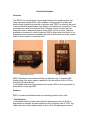
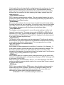
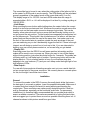
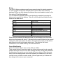
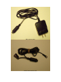
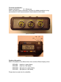
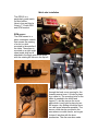
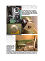
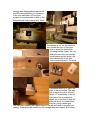
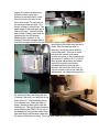
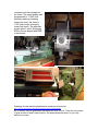
DRO-2
2-axis digital readout box
User Manual
Feb-14-2003
Product Description
Overview
The DRO-2 is a multi-function remote digital readout box displaying both two
linear axes and spindle RPM. It also displays cutting speeds on a lathe and
electronically signals limit positions to a power feed. DRO-2 is meant to be used
in conjunction with digital scales, that feature a 4-pin data port connection. These
are usually no-name units imported from China by various vendors and can
easily be found on ebay using search words DRO, quill kit or scale. They are
available as horizontal or vertical units and DRO-2 works with both kinds. In our
experience these units are remarkably accurate for their price and make a great
basis for axis readouts on machine tools.
horizontal type scale
vertical type scale
DRO-2 interfaces to two scales and has five digit plus sign 7-segment LED
displays that offer vastly superior readability over the scale’s built-in LCDs or
external LCD based boxes.
It is available with either high intensity red or green LEDs in a housing made of
either black or light gray ABS.
Features
DRO-2 is packed with features that no competing product has to offer.
- Fast Readout In standard mode the scales output about 3 readings per second, which is
appropriate for calipers and well matched to the low refresh rate of LCDs. The
scales also have a fast readout mode of about 40 to 50 readings per second.
Unfortunately this mode is practically useless because the readings are too noisy
and blur the last digit on LCDs. Not so on DRO-2. We implemented a smart
digital signal processing filter that eliminates the readout noise to give a stable
display when the scale sits still while retaining fast display updates when the
scale is moving.
- Dual Display Functions DRO-2 has two separate display settings. The user toggles between the two by
pressing the center (mode) button. The two settings are freely programmable, to
display any of the different modes.
- Zero Buttons Of course, each scale has its own zero button located to the left of each display.
Pressing the button will zero the display. It should be noted, that since the scales’
own LCDs cannot be zeroed in high speed mode their reading will not change.
Not a problem, because you will never have to look at them again…
- Inch / MM modes The displays can be programmed to convert the scale readings to either inch
(imperial) or mm (metric). The range in mm mode is -999.99 to +999.99 with a
resolution of 0.01 mm. In inch mode the range is –99.9995 to +99.9995 inches
with a resolution of 0.0005 inches. The half mil is displayed by the decimal point
to the right of the least significant digit.
- Sign Selection The direction of the scale readout can be programmed. This allows the scale to
be mounted in a way that is easiest from a mechanical viewpoint without having
to worry about the direction of the readout. This is programmed once during
setup and retained in non-volatile memory.
- Diameter Mode –
Each display can be programmed to read either 1x (radius) or 2x (diameter). 1x
is the normal mode as it should be used on a milling machine for example. The
2x mode is useful for lathe cross slides when the user is more likely to be
interested in the diameter of a part being turned. Just make sure to turn it back to
1x when using a milling attachment on your lathe.
- RPM Mode DRO-2 has an input for an optional photo-interrupter sensor on the upper scale
connector to detect the rotation of a spindle and display its RPM. The range is 30
to just under 100,000 RPM.
When the range is exceeded either –SLO- or –HI- will be displayed. The RPM
number is updated once per spindle rotation, but no more than 4 times a second
to facilitate easy readout.
- SFM Mode DRO-2, when equipped with an RPM sensor, also calculates cutting speeds in
surface feet per minute for lathes. This works by taking the reading from the
upper scale, which on a lathe should be connected to the cross slide, and
calculating the cutting speed using the following formula:
SFM=RPM * 2 * Pi * cross slide reading in inches / 12
The cross slide has to be set to zero when the cutting edge of the lathe tool bit is
at the center for SFM mode to work correctly. The SFM reading will be calculated
properly regardless of the readout mode of the cross slide scale (1x or 2x)
The display range is 0 to 100,000. Just as in RPM mode when the range is
exceeded either –SLO- or –HI- will be displayed. Just don’t try cutting anything at
100,000 SFM…
- Limit Stops When pressing the zero button while holding down the center button the current
position is stored as an electronic limit. Whenever the scale is moved across this
position a pin on the lower scale connector changes logic states. This can be
used by some external circuit to stop a power feed and thereby limiting a cut to
not go beyond the set position. The two scales have separate limit memories, but
act on the same pin. This shouldn’t be a limitation even if a lathe or mill has two
power feeds as they wouldn’t be used at the same time. Just make sure to set
the limit of the unused axis at a position outside the work envelope of the part
you are machining so you don’t accidentally trigger the limit bit. If there is enough
interest, we will design a control box to hook up to this. If you are interested in
building your own circuit please contact us, so we can help you get started.
- Display Off Removing power from the DRO-2 box will erase position information and the
scales will be reset to zero on power-up. When you want to turn off the display
without losing position, just press the center button for 3 seconds. The scales are
still being read, so it will keep track of position. Pressing any button will turn the
display back on. This is a handy feature to have if your machine shop also
happens to be your bedroom (!?!) and you can’t sleep under the bright light of our
high efficiency LEDs…
- Data Output For use with future products all readings are also sent out over a serial data link
on two unused pins of the power connector. We currently have no concrete plans
for this, but thought it would be nice to have…
Installation
General
To connect the scales to the DRO-2 remove the small plastic slider that covers
the data port of your scale or caliper. Insert the supplied data cable. Make sure it
is seated firmly and straight. Be careful to avoid jamming and bending the
contact pins. These connectors are rather poorly designed and don’t hold too
well by themselves, especially on the horizontal scale units. For permanent
installations it is therefore highly recommended that you provide strain relief to
assure a reliable connection. The scales are sensitive to cutting fluid and chips
and we suggest you to protect them as much as possible. Mounting them in a Uchannel as shown in this picture would be a good idea.
horizontal scale mounted in U-channel (hardwired cabling)
It is important to mount the scales in a way that the head can move freely along
the entire length. This is not all that easy to achieve, since binding in a completed
assembly is difficult to detect when the table is driven by a lead screw. The best
way is usually to mount the scale first and measure the position of the sliding
head relative to its desired mounting point at both extremes o f the motion. Then
adjust one or both mounting points of the scale and repeat the process until the
head’s position perpendicular to the motion remains the same at both ends. Now
you can attach the mounting bracket for the head. A good bracket design will
allow some adjustment for alignment. The bracket in the picture was mounted by
sliding it up on the 45deg slope until it sat flush with the back plate mounted to
the scale’s head. The mounting screws to the base were then tightened followed
by the screws i nto the back plate. Some slop or oval holes are needed to give
room for this adjustment.
Some thought should be given to the cable routing. A strain relief at the mounting
bracket of the head is mandatory and the cable should be routed to a place
where any loop formed by the movement of the table or carriage will not interfere
with the cutting action or the removal of chips.
The DRO-2 box itself should also be mounted away from any cutting fluid and
chips.
Setup
The DRO-2 display modes are easily programmed using this simple procedure.
To enter program mode press all three buttons at the same time until P0 is
displayed. When you then release the buttons the current readout modes for the
first setting (P0) will be displayed.
You can select the desired mode for each display by repeatedly pressing the
button next to each of the displays. This will cycle through the available modes
shown in the table below.
1.000
2.000
-1.000
-2.000
1.00
2.00
-1.00
-2.00
0
F
Inch mode
Inch mode diameter
Inch mode reverse direction
Inch mode diameter reverse
mm mode
mm mode diameter
mm mode reverse direction
mm mode diameter revers
RPM mode
SFM mode
When you have selected the desired modes for each display press the center
button and the display will show P1 followed by the current modes for the second
setting (P1) when you release the button. Now select the modes just like before
and press the center button again when done. This will store the mode
information in non-volatile memory and reset the DRO-2.
Cross Slide Zeroing
Here is the easiest way to zero a cross slide on a lathe:
Take a scrap piece of round stock and turn it down just enough to get a smooth
surface all around. Zero the cross slide reading and take out the piece. Measure
the diameter of the section yo u just turned with some calipers. Move the cross
slide in until the display reads minus the diameter you measured (or half that if
you like to run your lathe in radius mode). Hit zero again and you’re done until
you change tools or move your compound.
DRO-2 power supply
DRO-2 scale interface cable
Troubleshooting
Display only reads –OFF-:
Make sure the connectors are plugged into the scales properly. On rare
occasions, a scale can lock up and can only be revived by removing its battery.
A more intricate reason for a scale misbehaving can be a ground loop. The
scale’s body is electrically connected to the positive supply of the battery. This
puts it at about 1.5V relative to the ground reference of the DRO-2. If you are
using your own 5 Volt power source make sure that is floating relative to earth
ground, else you would be shorting the scale’s power supply if the machine that
the scale is attached to is grounded as it should be. The power supplies we
supply have no connection between ground and earth ground. Be aware that you
can also create an unintended ground connection via the RPM sensor or limit
output. Make sure that the RPM sensor’s ground is not connected to earth
ground and use an opto-isolator to avoid grounding issues on the limit output.
Display shows –LO-:
This can happen on startup when the reading is out of range with a large
negative number. The condition can be cleared by pressing the zero button. If
this happens during normal operation it indicates that you might have a problem
with your cable connection or grounding issues.
Display shows –HI-:
This code is shown under two conditions. The first is when similar to when the
display shows –LO- except that the reading is out of range on the positive side.
The second scenario occurs in RPM or SFM mode when the readout would
exceed 100,000.
Display shows –SLO-:
This happens in RPM or SFM mode when the spindle speed drops below 30
RPM. This can also indicate a problem with the spindle sensor, if –SLO- is
displayed at faster spindle speeds.
Technical specification
Power consumption:
5V, 400mA max
DRO-2 provides power to the scales. However for reliable operation in noisy
environments it is still recommended to leave batteries in the scales.
pinout of connectors
scale connector pinout
Ordering information
DRO-2 is available in two different box colors and two different display colors.
DRO-2BG
DRO-2BR
DRO-2WG
DRO-2WR
black box, green display
black box, red display
light gray box, green display
light gray box, red display
Please check our web site for availability.
Contact
If you have further questions regarding this product or suggestions on how we
can improve it or this manual, please feel free to contact us by sending email to
[email protected]
Please visit us on the web at
http://www.zietlowdesign.com/products/products.htm
Mini-Lathe Installation
The DRO-2 is a
particularly good match
for Mini-Lathes.
Here is how we fitted a
Grizzly 7*12 with DRO
and RPM readout.
RPM sensor
The RPM sensor is a
photo interrupter module
that senses the passing
of a slot in a disc
mounted to the spindle of
the lathe. The sensor is
mounted on a right angle
sheet metal strip and is
attached to the back gear carrier plate
with the existing M6 screw in the top left
corner. The cable is routed to exit
through the back cover opening for the
forward-reverse lever. It is held in place
by a cable tie. The mounting hole for the
cable tie needed to be drilled and
tapped. To do this remove the cover
plate which is only held in place by two
M6 screws. Any drilling should be done
on a drill press whenever possible. The
sensor could also be mounted in the
area where our cable tie sits, as long as
it doesn’t interfere with the lever
mechanism. The disc was also made
out of sheet aluminum. We cut a 2.4”
square piece and centered it in the 4-jaw
and then bored out a 1.060” hole. Then
changed to the 3 -jaw chuck and held it
from the inside to turn the o utside to
2.300”. We then cut out a notch with a
nibbler to complete the disc, which was
then mounted between the two retaining
nuts for the spindle.
Scale Mounting
We used a 6”
horizontal scale for
the cross slide and a
12” vertical model
for the carriage (A 4”
scale should be
sufficient for the
cross slide). The
modifications to the
lathe itself were kept
to a minimum. The
center piece of the
mounts is an
aluminum L-bracket
that attaches to the rear of the carriage. The bodies of both scales are mounted
to this bracket. It is attached to the carriage by two M4 screws. The mounting
height was determined by the required clearance of the cross slide scale. The
carriage was disassembled (remove the
two M8 screws attaching it to the apron
in the front and slide it off) and then
scribed on a surface plate, drilled on the
drill press and finally tapped (M4). While
the carriage is off, we also added a
hole toward the front of the cross
slide to attach the cross slide
mounting bracket. Again, don’t try
drilling by hand, but use a scribe,
center punch and drill press. We
then mounted the cross slide
scale’s mounting block. The block
is designed with a lip to catch the
edge of the cross slide. This way
one screw is enough to securely
fasten it. The geometry of the top
of the block has a wedge that
allows the cover plate to grab the
slide with a line of contact rather
than flat, giving a better grip.
The next step is adding two tapped holes to the tail stock end of the lathe bed
casting. These holes are needed for the carriage slide end support. Both slides
are only supported on one side, making them easier to align. The picture shows
why we recommend doing all the
drilling in the drill press. Hand
drilling will invariably result in
offset holes like these making
alignment more difficult. The
block again is designed with a lip
to catch the edge of the casting,
so one screw would probably be
sufficient. Next we mounted the
scales to the L -bracket and fixed
the cables with two strain relief cable
ties. The cables exit near the front of
the bracket, but facing back. This is the
optimal position for using the existing
mounting holes (for the splash guard)
on the lathe’s bed casting for cable
guides. Now we were ready to fix the
carriage scale. When attaching the
carriage scale to the L-bracket, make
sure that it remains parallel to the
edges. Only minor angular error
should be taken up by the Lbracket to carriage mount, since
this will introduce a twist in the
cross slide scale. To test level on
the carriage scale we used 1-2-3
blocks as seen in this picture. The
upper edge of the scale was just a
little more than 1” below the lathe
bed surface. When it was level we
tightened the two M4 screws
attaching the L-bracket to the
carriage. Next the carriage slide is
fixed to the support block at the tail stock end. Some shims might be needed to
avoid flexing the scale near the end of
travel. After the carriage slide is
attached, we did the same with the
cross slide scale. This one is easier
because the scale’s body never
comes very close to the mounting end
(we used a 6” scale for 2.9” of travel).
Also angular adjustments are easier
since the mounting screws are
reachable without removing the Lbracket. We had to file down one of
the set screws for the cross slide gib
adjustments, as it was sticking out too
far and would have interfered with the
L-bracket. We took it out and filed its tip
down about 0.1” and reshaping the tip
to its original form. When put back in
place it ended up being flush with the
retaining nut. The only things remaining
were attaching the DRO-2 to the top of
the headstock using double sided foam
tape and tidying up the extra cable with
tie wraps to the motor housing. The cross slide cable goes into the upper display
connector and the carriage into
the lower. The upper display was
programmed to –2.000 (inch
diameter reading increasing
toward the user), the lower to
1.000 (inch mode, increasing
toward tail stock). The alternate
modes were F and 0, displaying
SFM in the top display and RPM
in the bottom.
Drawings for the mounting brackets we used can be found at
http://www.zietlowdesign.com/products/dro2/bracket/acwebpublish.htm
By no means can we guarantee that these will work for you. They are only meant
to give an idea of how it can be done. So please measure twice, so you only
have to cut once…