1
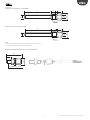
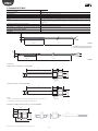
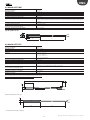
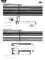
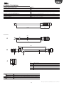
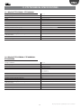
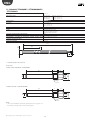
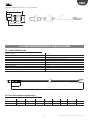
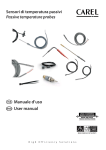
Sensori di temperatura passivi Passive temperature probes Manuale d’uso User manual NO POWER & SIGNAL CABLES TOGETHER READ CAREFULLY IN THE TEXT! Integrated Control Solutions & Energy Savings ENG IMPORTANT DISPOSAL OF THE PRODUCT CAREL bases the development of its products on decades of experience in HVAC, on the continuous investments in technological innovations to products, procedures and strict quality processes with in-circuit and functional testing on 100% of its products, and on the most innovative production technology available on the market. CAREL and its subsidiaries nonetheless cannot guarantee that all the aspects of the product and the software included with the product respond to the requirements of the final application, despite the product being developed according to start-of-the-art techniques. The customer (manufacturer, developer or installer of the final equipment) accepts all liability and risk relating to the configuration of the product in order to reach the expected results in relation to the specific final installation and/or equipment. CAREL may, based on specific agreements, acts as a consultant for the positive commissioning of the final unit/ application, however in no case does it accept liability for the correct operation of the final equipment/system. The product is made up of metal parts and plastic parts. In reference to European Union directive 2002/96/EC issued on 27 January 2003 and the related national legislation, please note that: 1. WEEE cannot be disposed of as municipal waste and such waste must be collected and disposed of separately; 2. the public or private waste collection systems defined by local legislation must be used. In addition, the equipment can be returned to the distributor at the end of its working life when buying new equipment; 3. the equipment may contain hazardous substances: the improper use or incorrect disposal of such may have negative effects on human health and on the environment; 4. the symbol (crossed-out wheeled bin) shown on the product or on the packaging and on the instruction sheet indicates that the equipment has been introduced onto the market after 13 August 2005 and that it must be disposed of separately; 5. in the event of illegal disposal of electrical and electronic waste, the penalties are specified by local waste disposal legislation. The CAREL product is a state-of-the-art product, whose operation is specified in the technical documentation supplied with the product or can be downloaded, even prior to purchase, from the website www.carel.com. Each CAREL product, in relation to its advanced level of technology, requires setup/configuration/programming/commissioning to be able to operate in the best possible way for the specific application. The failure to complete such operations, which are required/indicated in the user manual, may cause the final product to malfunction; CAREL accepts no liability in such cases. Only qualified personnel may install or carry out technical service on the product. The customer must only use the product in the manner described in the documentation relating to the product. In addition to observing any further warnings described in this manual, the following warnings must be heeded for all CAREL products: If the appliance is used in a way that is not described by the manufacturer, the specified level of protection may be affected. NO POWER & SIGNAL CABLES TOGETHER • Prevent the electronic circuits from getting wet. Rain, humidity and • • • • • all types of liquids or condensate contain corrosive minerals that may damage the electronic circuits. In any case, the product should be used or stored in environments that comply with the temperature and humidity limits specified in the manual. Do not install the device in particularly hot environments. Too high temperatures may reduce the life of electronic devices, damage them and deform or melt the plastic parts. In any case, the product should be used or stored in environments that comply with the temperature and humidity limits specified in the manual. Do not attempt to open the device in any way other than described in the manual. Do not drop, hit or shake the device, as the internal circuits and mechanisms may be irreparably damaged. Do not use corrosive chemicals, solvents or aggressive detergents to clean the device. Do not use the product for applications other than those specified in the technical manual. READ CAREFULLY IN THE TEXT! WARNING: separate as much as possible the probe and digital input signal cables from the cables carrying inductive loads and power cables to avoid possible electromagnetic disturbance. Never run power cables (including the electrical panel wiring) and signal cables in the same conduits All of the above suggestions likewise apply to the controllers, serial boards, programming keys or any other accessory in the CAREL product portfolio. CAREL adopts a policy of continual development. Consequently, CAREL reserves the right to make changes and improvements to any product described in this document without prior warning. The technical specifications shown in the manual may be changed without prior warning. The liability of CAREL in relation to its products is specified in the CAREL general contract conditions, available on the website www.carel.com and/or by specific agreements with customers; specifically, to the extent where allowed by applicable legislation, in no case will CAREL, its employees or subsidiaries be liable for any lost earnings or sales, losses of data and information, costs of replacement goods or services, damage to things or people, downtime or any direct, indirect, incidental, actual, punitive, exemplary, special or consequential damage of any kind whatsoever, whether contractual, extra-contractual or due to negligence, or any other liabilities deriving from the installation, use or impossibility to use the product, even if CAREL or its subsidiaries are warned of the possibility of such damage. 3 Passive probe man. +030220655 - rel. 1.6 - 02.12.2011 ENG Content 1. INTRODUCTION 7 1.1 General description ............................................................................................................ 7 2. NTC TECHNICAL SPECIFICATIONS 7 2.1 Models NTC*HP* ................................................................................................................ 7 2.2 Models NTC*WF* ................................................................................................................ 8 2.3 Models NTC*WP* ................................................................................................................ 8 2.4 Models NTC*WH* ............................................................................................................. 10 2.5 Models NTC*WG* ............................................................................................................. 11 2.6 Models NTC*HT* ............................................................................................................... 11 2.7 Models NTC*HF* ............................................................................................................... 12 2.8 Models NTC*PS* ............................................................................................................... 12 3. NTC IMMERSION PROBE TECHNICAL SPECIFICATIONS 13 3.1 Model TSN1300000........................................................................................................... 13 3.2 Model TSC1500030........................................................................................................... 14 4. NTC PIERCING PROBE TECHNICAL SPECIFICATIONS 16 4.1 Models NTC*INF* .............................................................................................................. 16 4.2 Model NTCINF0340 ...........................................................................................................17 5. TABLE OF TEMPERATURE VALUES 18 Table of temperature-resistance values for NTC sensor 10K@25°C ß 3435 ............. 18 Table of temperature-resistance values for NTC sensor 50K@25°C ß 3977.............. 19 6. PT100 PROBE TECHNICAL SPECIFICATIONS 20 6.1 Models PT100 .....................................................................................................................20 7. TABLE OF TEMPERATURE VALUES PT100 PROBE 21 7.1 Table of temperature values PT100 Probe Class B...................................................... 21 8. PT1000 PROBE TECHNICAL SPECIFICATIONS 22 8.1 Models PT1*HP* ...............................................................................................................22 8.2 Models PT1*WF* ...............................................................................................................22 8.3 Models PT1*WP* ...............................................................................................................23 8.4 PT1*HT* Models...............................................................................................................24 8.5 Models PT1*HF ..................................................................................................................24 8.6 Models PT1*PS* ................................................................................................................25 9. PT1000 IMMERSION PROBE TECHNICAL SPECIFICATIONS 26 9.1 Model TST1300000............................................................................................................26 9.2 Model TSM1500B30 .........................................................................................................27 9.3 Models TSQ15MAB00 ......................................................................................................29 10. PT1000 PIERCING PROBE TECHNICAL SPECIFICATIONS 30 10.1 Model PT1INF0340 .........................................................................................................30 11. PTC TECHNICAL SPECIFICATIONS 31 11.1 Models PTC0150000 – PTC0600000 ........................................................................... 31 11.2 Models PTC015W000 - PTC060W000 - PTC060WA00 ............................................ 31 11.3 Models PTC03000W1 - PTC03003000D1 - PTC03000G1 ......................................32 12. LIGHT SENSOR TECHNICAL SPECIFICATIONS 33 12.1 Model PSOPZLHT00 ......................................................................................................33 12.2 Sensitive element specifications..................................................................................33 13. ACCESSORIES 34 5 Passive probe man. +030220655 - rel. 1.6 - 02.12.2011 ENG 1. INTRODUCTION 1.1 General description The Carel passive temperature probes are devices that, when connected to the controller, provide a resistance value, which is then converted to a temperature by the electronic controller. These are used in HVAC/R applications, and represent a complete range capable of satisfying a variety of needs in different installations. The probes are made using materials that guarantee constant quality. The range includes various models that differ based on the performance of the system and the fields of application. The probes have different types of sensor (NTC, PTC, Pt1000), caps, index of protection, cable length, operating ranges and mechanical dimensions. In addition, models are available for use in hydronic systems, applied directly onto the tubing, which simplify installation and offer a faster response in the reading, improving the wiring of the HVAC/R unit and improving performance. The probes are used together with Carel electronic controllers (parametric and programmable). 2. NTC TECHNICAL SPECIFICATIONS 2.1 Models NTC*HP* Storage conditions Operating range Connections Sensor Dissipation factor (in air) -20T70 °C -50T105 °C in air -50T50 °C in fluid Stripped ends, dimensions: 5±1 mm NTC 10 kΩ ±1% at 25 °C Beta 3435 approx. 3 mW/°C Thermal constant over time (in air) Cable Sensitive element index of protection Sensitive element housing approx. 75 s Black two-wire flat cable, with tinned copper wire size 0.3 mm2 IP67 Polyolefin 6x5 Classification according to protection against electric Basic insulation for 250 Vac shock (sensitive element & cable) Category of resistance to heat and fire Flame retardant Standard NSF L=* 15 * = see table of product codes in price list Warning: all measures present in this manual are in millimeters. 7 Passive probe man. +030220655 - rel. 1.6 - 02.12.2011 ENG 2.2 Models NTC*WF* Storage conditions -20T70 °C Operating range -50T105 °C Connections Sensor Stripped ends, dimensions: 5±1 mm Dissipation factor (in air) Thermal constant over time (in water) Cable approx. 7 mW/°C NTC 10 kΩ ±1% at 25 °C Beta 3435 approx. 4.5 s Two-wire with double sheath, AWG22, tinned copper with electrical resistance ≤63 Ω/km - Insulation: TPE specific for immersion in water on outer sheath, PP/Co inside on wires, OD 3.5 mm max. IP67 Ø4 Sensitive element index of protection AISI 316 steel diameter 4 mm - L= 30 mm Sensitive element housing Classification according to protection against electric shock Basic insulation for 250 Vac; (sensitive element & cable) Flame retardant Category of resistance to heat and fire L =* 40 * = see table of product codes in price list 2.3 Models NTC*WP* -20T70 °C -50T105 °C Stripped ends, dimensions: 5±1 mm NTC 10 kΩ ±1% at 25 °C Beta 3435 approx. 2.2 mW/°C approx. 20 s Two-wire with double sheath, AWG22, tinned copper with electrical resistance ≤63 Ω/ km - Insulation: TPE specific for immersion in water on outer sheath, PP/Co inside on wires, OD 3.5 mm max Sensitive element index of protection IP68 Immersion in water 1 m depth for 200 h at 70 °C Resistance in autoclave to saturated steam 30 min. at 105 °C Sensitive element housing PP/Co with AISI 316 outer cap Classification according to protection against electric Supplementary insulation for 250 Vac; shock (sensitive element & cable) Category of resistance to heat and fire Flame retardant Standard NSF Ø6 Storage conditions Operating range Connections Sensor Dissipation factor (in air) Thermal constant over time (in water) Cable LC =** L =* Version 1 * = see table of product codes in price list Ø6 * *= 52/100/200/300(mm dimension) CAREL NTC015WP00 IP65-50T105 14/06 BT L =* LC=** Version 2 Passive probe man. +030220655 - rel. 1.6 - 02.12.2011 8 ENG Accessories Socket: nickel-coated brass - 1413306AXX Ø 6.5 CH 16 CH 17 11 Ø 8.5 3 Ø 6.5 9 60 1/4 gas Socket 2: AISI 316 - code 1413309AXX 9 3 11 Ø 7.5 60 1/4 gas Note: • cable secured with PG7 - IP68 cable gland applied to hexagonal end • kit available complete with socket and cable gland Compression fitting with metal olive - code 1309589AXX 29.5 10 CH 17 Ø6 1/4” GAS Ø 6 mm AISI 316 9 Passive probe man. +030220655 - rel. 1.6 - 02.12.2011 ENG 2.4 Models NTC*WH* -20T70 °C -50T105 °C Stripped ends, dimensions: 5±1 mm NTC 10 kΩ ±1% at 25 °C Beta 3435 approx. 2.2 mW/°C approx. 20 s Two-wire with double sheath, AWG22, tinned copper with electrical resistance ≤63 Ω/km - Insulation: TPE specific for immersion in water on outer sheath, PP/Co inside on wires, OD 3.5 mm max Sensitive element index of protection IP68 Sensitive element housing PP/Co with AISI 316 outer cap Classification according to protection against electric Supplementary insulation for 250 Vac; shock (sensitive element & cable) Category of resistance to heat and fire Flame retardant Standard NSF Ø6 Storage conditions Operating range Connections Sensor Dissipation factor (in air) Thermal constant over time (in water) Cable LC =** L =* Version 1 * = see table of product codes in price list Ø6 * *= 52/100/200/300(mm dimension) CAREL NTC*WH* IP68-50T105 W/YY L =* LC=** Version 2 Accessories Socket: nickel-coated brass - 1413306AXX Ø 6.5 CH 16 CH 17 11 Ø 8.5 3 Ø 6.5 9 60 1/4 gas Socket 2: AISI 316 - code 1413309AXX 9 3 Ø 7.5 60 11 1/4 gas Note: • cable secured with PG7 - IP68 cable gland applied to hexagonal end • kit available complete with socket and cable gland Compression fitting with metal olive - code 1309589AXX 29.5 10 CH 17 Ø6 1/4” GAS Ø 6 mm AISI 316 Passive probe man. +030220655 - rel. 1.6 - 02.12.2011 10 ENG 2.5 Models NTC*WG* Storage conditions Operating range Connections Sensor Dissipation factor (in air) Thermal constant over time (in air) Cable -20T70 °C -50T105 °C Stripped ends, dimensions: 5±1 mm NTC 10 kΩ ±1% at 25°C Beta 3435 approx. 1 mW/°C approx. 10 s Two-wire with double sheath, AWG22, tinned copper with electrical resistance ≤63 Ω/km Insulation: TPE specific for immersion in water on outer sheath, PP/Co inside on wires, OD 3.5 mm max. Sensitive element index of protection IP67 (polyurethane resin) Sensitive element housing Aluminium 6x6x40 Classification according to protection against electric Basic insulation for 250 Vac; shock (sensitive element & cable) Category of resistance to heat and fire Flame retardant * = see table of product codes in price list Cap for probe sensor 6 6 3.3 40 L=* 2.6 Models NTC*HT* Storage conditions Operating range Connections Sensor Precision -20T70 °C 0T150 °C in air Stripped ends, dimensions 6±1mm R(25 °C)= 50 kOhm 1%; Beta (25/85)3977±1% +/- 0.5 °C; -10T50 °C +/- 1.0 °C; -50T85 °C +/- 1.6 °C; +85T120 °C +/- 2.1 °C; +120T150 °C Dissipation factor (in air) approx. 3 mW Thermal constant over time (in air) approx. 60 s Cable High temperature polyester (diam. 4x2 max.) Sensitive element index of protection IP55 Sensitive element housing High temperature polyester dim. 20x5 mm (available in version with AISI 316 stainless steel cap) Classification according to protection against electric Basic insulation for 250 Vac shock (sensitive element & cable) Category of resistance to heat and fire In accordance with CEI 20-35 Insulation resistance at 1000 Vdc >100 mOhm Dielectric strength 1500 Vac Note: the NTC*HT probes cannot be used with extended exposure to water and must not be used at temperatures below 0 °. L= * 6 ø5 0.1 20 0.5 Ø5 Version with stainless steel cap INOX 50 L=* * = see table of product codes in price list 11 Passive probe man. +030220655 - rel. 1.6 - 02.12.2011 ENG 2.7 Models NTC*HF* Storage conditions Operating range -20T70 °C -50T90 °C Connections Sensor Stripped ends, dimensions 6±1mm R(25 °C)= 10 kOhm 1%; Beta 3435 Precision Dissipation factor (in air) Thermal constant over time (in water) Cable Sensitive element index of protection Sensitive element housing Class. according to protection against electric shock Category of resistance to heat and fire Insulation resistance at 500 Vdc Dielectric strength +/- 0.5 °C at 25 °C; +/- 1.0 °C from -50T90 °C 3 mW approx. 15 s Black, thermoplastic rubber flat cable (diam. 3.6x1.6 max.) IP67 Thermoplastic with fastening clamp Basic insulation for 250 Vac UL/HB cable >20 mOhm 1500 Vac 6 cap frontal view 110 6 20 thermoplastic rubber contact L=* * = see table of product codes in price list cable section 2.8 Models NTC*PS* -20T70 °C -50T105 °C Stripped and soldered ends, dimensions: 4±1 mm NTC 10 kΩ ±1% a 25 °C Beta 3435 2 mW/°C ca. / approx. 50 min (V=1 m/s) Two-wire with double sheath, AWG22, tinned copper with resistance ≤73.9Ω/km Insulation: TPE specific for immersion in water on outer sheath, PP/co inside on wires, OD 3.30+/-0.10 mm Sensitive element index of protection IP67 Case RAL7032 grey Santoprene Food safe Classification according to protection against electric shock Supplementary insulation for 250 Vac (sensitive element & cable) Category of resistance to heat and fire Flame retardant 20 Storage conditions Operating range Connections Sensor Dissipation factor (in air) Thermal constant over time (in air) Cable Magnetic base Make a hole for fastening by screw 98 CAREL code 105 L =* * = see table of product codes in price list Passive probe man. +030220655 - rel. 1.6 - 02.12.2011 12 ENG 3. NTC IMMERSION PROBE TECHNICAL SPECIFICATIONS 3.1 Model TSN1300000 Immersion probes feature the sensor directly in contact with the liquid, and are installed on the tubing. Wired using the electrical connector. Storage conditions Operating range Sensor Construction Electrical connection Thermal const. over time (in water) Sensitive element housing Insulation Maximum operating pressure -20T70 °C -40T120 °C NTC 10 k ±1% at 25 °C Beta 3435 Direct immersion with connection to the 1/8” GAS male process fitting as per UNI 338 4-pin co-moulded nylon, M12x1 (DIN-VDE0627) metric thread, IP67 max. temp. 90 °C approx. 5 s AISI 316 100 Mohm at 500 Vdc 40 bars 55.5 NTC sensitive element 10 Kohm Stainless steel socket EX14 Co-moulded body M12 male connector 13 Ø3 1/8” GAS 1 2 3 4 5 2 1 3 4 5 Accessories: Wiring: • 4-pin M12 connector for 1/8 GAS sensor - cable length 3 m Code TSOPZCW030 1 L=* 2 3 150 NTC 10kohm 1 2 3 red red white • 4-pin M12 connector for 1/8 GAS sensor Code TSOPZCM000 M12 connector can be assembled on site, recommended cable 3x0.2 mm2 with outer sheath. 2 3 NTC 10k 1 4 Sensor connector side view 1/8” GAS cyl. fitting for sensor 1/4” GAS cyl. process fitting with immersion L= 10.5 mm B 1/8” GAS CIL. EX 17 A B Ø 4.8 Code TSOPZPT000 25.5 10.5 Ø4 1/4” GAS CIL. • Probe socket 1/4 Gas A 18 • Welding fitting 3,5 Code TSOPZCW030 17 13,5 13 Passive probe man. +030220655 - rel. 1.6 - 02.12.2011 ENG 3.2 Model TSC1500030 Immersion probes feature the sensor directly in contact with the liquid and are secured to the tubing using a connector, available in the screw or weldable versions. The body is nickel-coated brass, index of protection IP67, and the gasket (O-ring) is supplied together with the probe. Storage conditions Operating range Sensor Construction Cable Thermal constant over time (in water) Sensitive element housing Insulation Maximum operating pressure Compatible liquids -20T70 °C -40T90 °C NTC 10 kΩ ±1% at 25 °C Beta 3435 Direct immersion with connection to M14 male process fitting 2 wires AWG 22, with TPE sheath approx. 5 s Nickel-coated brass & grey PA6 co-moulded body 100 Mohm at 100 Vdc 25 bar Water, Oil 23 E= 2000±30 Ø9.5 ~7.5 EX14 ~40 1 sensitive element nickel-coated brass locking ring co-moulded body cable marking tinned copper 2-wire cable NTC sensor 2015 O-ring nickel-coated brass thermometer socket 3 4 7 Black NTC 10 kOhm @ 25 °C ±1% β(25/85)= 3435 Passive probe man. +030220655 - rel. 1.6 - 02.12.2011 14 15 6 3 M14x1 Ø 3.5 Ø 10 Ø4 Wiring White 5 8 Ø 12.5 1 2 3 4 5 6 7 8 2 ENG Accessories: Adapter from M14 to 3/8 GAS Code TSOPZRV000 ø 20 CH 17 ø= 14.9 6 M14x1 17 1 ø4.1 10.5 3/8” 2 7 8 Weldable adapter for M14 Code TSOPZRS000 ø 16 M 14x1 17 6 2 10.5 ø 4.1 A A 1 3/8 cyl. threaded fitting with round seat, nickel-coated brass 2 weldable cylindrical fitting with round seat, brass code: C058042A04 code C058042A03 15 Passive probe man. +030220655 - rel. 1.6 - 02.12.2011 ENG 4. NTC PIERCING PROBE TECHNICAL SPECIFICATIONS 4.1 Models NTC*INF* Piercing probes with “L” and “T” handle Storage conditions Operating range Connections Sensor Dissipation factor (in air) Thermal constant over time (in air) Cable -20T70 °C -50T90 °C Stripped ends, dimensions: 5±1 mm NTC 10 kOhm ±1% at 25 °C Beta 3435 approx. 2.2 mW/°C approx. 10 s Two-wire with double sheath, tinned copper wire size 0.35 mm2 with electrical resistance ≤63 Ohm/km Sensitive element index of protection IP67 Sensitive element housing AISI 304 stainless steel with silicone resin filling Classification according to protection against electric Insulation: silicone both on outer sheath and inside on wires shock (sensitive element & cable) Category of resistance to heat and fire Flame retardant 6000 NTCINF600* 150 90 Ø5 Ø9 40 NTCINF610* 225 36 4 137 L= * 13 * = see table of product codes in price list Passive probe man. +030220655 - rel. 1.6 - 02.12.2011 16 8 169 ENG 4.2 Model NTCINF0340 Piercing probe with “L” handle and heating system Storage conditions -20T70 °C Operating range -50T90 °C Connections Stripped ends, with terminals Sensor NTC 10 kOhm ±1% at 25 °C Beta 3435 Thermal constant over time (in water) approx. 10 s Cable Food-safe thermoplastic sheath with 4 wires size 0.15 mm2 Wire colours White-black, NTC / red, electric heater. Maximum heater voltage 24 Vac Electrical resistance of heater 7 Ohm ±0.6 Cable length 3m Sensitive element index of protection IP67 Sensitive element housing AISI 316 stainless steel. Length 100 mm diam. 4 mm. With pointed tip. Cap filler Aluminium Classification according to protection against electric shock Insulation: Outer sheath, and inside on wires (sensitive element & cable) Category of resistance to heat and fire Flame retardant Insulation resistance 20 Mohm 500 Vdc Dielectric strength 500 Vac 100 Ø4 6 aa 3000 bb a red, electric heater b white/black, NTC 17 Passive probe man. +030220655 - rel. 1.6 - 02.12.2011 ENG 5. TABLE OF TEMPERATURE VALUES Table of temperature-resistance values for NTC sensor 10K@25°C ß 3435 Temp. Resistance value °C -50 -49 -48 -47 -46 -45 -44 -43 -42 -41 -40 -39 -38 -37 -36 -35 -34 -33 -32 -31 -30 -29 -28 -27 -26 -25 -24 -23 -22 -21 -20 -19 -18 -17 -16 -15 -14 -13 -12 -11 -10 -9 -8 -7 -6 -5 -4 -3 -2 -1 0 Max. KΩ 344,60 325,00 306,60 289,40 273,40 258,30 244,20 231,00 218,60 207,00 196,00 185,50 175,60 166,30 157,60 149,40 141,70 134,50 127,70 121,20 115,20 109,40 103,90 98,68 93,80 89,20 84,85 80,76 76,89 73,23 69,77 66,44 63,30 60,32 57,51 54,85 52,33 49,95 47,69 45,55 43,52 41,55 39,69 37,92 36,25 34,66 33,15 31,72 30,36 29,06 27,83 Typical KΩ 329,50 310,90 293,50 277,20 262,00 247,70 234,30 221,70 209,90 198,90 188,50 178,50 169,00 160,20 151,90 144,10 136,70 129,80 123,30 117,10 111,30 105,70 100,50 95,52 90,84 86,43 82,26 78,33 74,61 71,10 67,77 64,57 61,54 58,68 55,97 53,41 50,98 48,68 46,50 44,43 42,47 40,57 38,77 37,06 35,44 33,90 32,44 31,05 29,73 28,48 27,28 Min. KΩ 314,90 297,30 280,90 265,40 251,00 237,40 224,70 212,80 201,60 191,00 181,10 171,60 162,60 154,20 146,30 138,80 131,80 125,20 119,00 113,10 107,50 102,20 97,20 92,45 87,97 83,73 79,74 75,96 72,39 69,01 65,82 62,74 59,83 57,07 54,46 51,99 49,65 47,43 45,32 43,33 41,43 39,60 37,86 36,21 34,64 33,15 31,73 30,39 29,11 27,89 26,74 Passive probe man. +030220655 - rel. 1.6 - 02.12.2011 Temp. Resistance value °C 1 2 3 4 5 6 7 8 9 10 11 12 13 14 15 16 17 18 19 20 21 22 23 24 25 26 27 28 29 30 31 32 33 34 35 36 37 38 39 40 41 42 43 44 45 46 47 48 49 50 51 52 53 54 55 Max. KΩ 26,65 25,52 24,44 23,42 22,45 21,53 20,64 19,81 19,01 18,25 17,51 16,81 16,14 15,50 14,89 14,31 13,75 13,22 12,72 12,24 11,77 11,32 10,90 10,49 10,10 9,73 9,38 9,04 8,72 8,41 8,11 7,83 7,55 7,29 7,04 6,79 6,56 6,34 6,12 5,92 5,72 5,53 5,34 5,17 5,00 4,83 4,68 4,52 4,38 4,24 4,10 3,97 3,85 3,73 3,61 Typical KΩ 26,13 25,03 23,99 23,00 22,05 21,15 20,30 19,48 18,70 17,96 17,24 16,56 15,90 15,28 14,69 14,12 13,58 13,06 12,56 12,09 11,63 11,20 10,78 10,38 10,00 9,63 9,28 8,94 8,62 8,31 8,01 7,73 7,45 7,19 6,94 6,70 6,47 6,25 6,03 5,83 5,63 5,44 5,26 5,08 4,91 4,75 4,59 4,44 4,30 4,16 4,03 3,90 3,77 3,65 3,54 18 Min. KΩ 25,62 24,55 23,54 22,57 21,66 20,78 19,95 19,15 18,39 17,67 16,97 16,30 15,67 15,06 14,48 13,92 13,39 12,89 12,40 11,94 11,50 11,07 10,66 10,27 9,90 9,53 9,18 8,84 8,52 8,21 7,92 7,63 7,36 7,10 6,85 6,61 6,37 6,15 5,94 5,74 5,54 5,35 5,17 4,99 4,83 4,67 4,51 4,36 4,22 4,08 3,95 3,82 3,70 3,58 3,46 Temp. Resistance value °C 56 57 58 59 60 61 62 63 64 65 66 67 68 69 70 71 72 73 74 75 76 77 78 79 80 81 82 83 84 85 86 87 88 89 90 91 92 93 94 95 96 97 98 99 100 101 102 103 104 105 106 107 108 109 110 Max. KΩ 3,50 3,39 3,28 3,18 3,09 2,99 2,90 2,82 2,73 2,65 2,57 2,50 2,42 2,35 2,28 2,22 2,15 2,09 2,03 1,98 1,92 1,87 1,81 1,76 1,72 1,67 1,62 1,58 1,54 1,49 1,45 1,42 1,38 1,34 1,31 1,27 1,24 1,21 1,17 1,14 1,12 1,09 1,06 1,03 1,01 0,98 0,96 0,93 0,91 0,89 0,87 0,84 0,82 0,80 0,79 Typical KΩ 3,43 3,32 3,22 3,12 3,02 2,93 2,84 2,75 2,67 2,59 2,51 2,44 2,36 2,30 2,23 2,16 2,10 2,04 1,98 1,92 1,87 1,82 1,77 1,72 1,67 1,62 1,58 1,53 1,49 1,45 1,41 1,37 1,34 1,30 1,27 1,23 1,20 1,17 1,14 1,11 1,08 1,05 1,02 1,00 0,97 0,95 0,92 0,90 0,88 0,86 0,84 0,82 0,80 0,78 0,76 Min. KΩ 3,35 3,25 3,15 3,05 2,95 2,86 2,77 2,69 2,61 2,53 2,45 2,38 2,31 2,24 2,17 2,11 2,05 1,99 1,93 1,87 1,82 1,77 1,72 1,67 1,62 1,58 1,53 1,49 1,45 1,41 1,37 1,33 1,30 1,26 1,23 1,19 1,16 1,13 1,10 1,07 1,04 1,02 0,99 0,97 0,94 0,92 0,89 0,87 0,85 0,83 0,81 0,79 0,77 0,75 0,73 ENG Table of temperature-resistance values for NTC sensor 50K@25°C ß 3977 Temperature Typical resistance TCR Min. resistance Max. resistance % Tolerance value value °C -40 KΩ 1630.77 %/°C -6.623 KΩ 1559.17 KΩ 1705.49 Min. -4.39 Max. 4.58 Min. 0.66 Max. -0.69 -35 -30 -25 -20 -15 -10 1178.11 860.97 636.08 474.78 357.83 272.18 -6.385 -6.161 -5.950 -5.751 -5.562 -5.384 1130.05 828.44 613.91 459.57 347.35 264.93 1228.08 894.68 658.99 490.44 368.59 279.59 -4.08 -3.78 -3.49 -3.20 -2.93 -2.66 4.24 3.92 3.60 3.30 3.01 2.73 0.64 0.61 0.59 0.56 0.53 0.49 -0.66 -0.64 -0.61 -0.57 -0.54 -0.51 -5 0 5 10 15 20 25 30 35 40 45 50 55 60 65 70 75 80 208.83 161.56 125.97 98.96 78.29 62.37 50.00 40.34 32.73 26.71 21.92 18.08 14.99 12.48 10.44 8.78 7.41 6.28 -5.214 -5.053 -4.900 -4.755 -4.616 -4.483 -4.357 -4.236 -4.120 -4.009 -3.903 -3.801 -3.704 -3.610 -3.519 -3.433 -3.349 -3.269 203.81 158.08 123.56 97.30 77.16 61.61 49.50 39.85 32.27 26.28 21.52 17.72 14.66 12.19 10.18 8.54 7.20 6.09 213.96 165.10 128.41 100.63 79.43 63.13 50.50 40.83 33.20 27.15 22.32 18.45 15.32 12.78 10.72 9.02 7.63 6.48 -2.41 -2.15 -1.91 -1.67 -1.44 -1.22 -1.00 -1.21 -1.42 -1.62 -1.81 -2.00 -2.19 -2.36 -2.54 -2.71 -2.87 -3.03 2.45 2.19 1.94 1.69 1.45 1.22 1.00 1.22 1.43 1.64 1.84 2.03 2.22 2.41 2.59 2.77 2.95 3.12 0.46 0.43 0.39 0.35 0.31 0.27 0.23 0.29 0.34 0.40 0.46 0.53 0.59 0.65 0.72 0.79 0.86 0.93 -0.47 -0.43 -0.40 -0.36 -0.31 -0.27 -0.23 -0.29 -0.35 -0.41 -0.47 -0.53 -0.60 -0.67 -0.74 -0.81 -0.88 -0.95 85 90 95 100 105 110 115 120 125 130 135 140 145 150 5.34 4.56 3.91 3.37 2.91 2.52 2.19 1.91 1.67 1.46 1.28 1.13 1.00 0.89 -3.191 -3.117 -3.045 -2.975 -2.908 -2.843 -2.781 -2.720 -2.662 -2.605 -2.551 -2.498 -2.446 -2.396 5.17 4.41 3.78 3.24 2.80 2.42 2.10 1.83 1.59 1.40 1.22 1.08 0.95 0.84 5.52 4.72 4.05 3.49 3.02 2.62 2.28 1.99 1.74 1.53 1.34 1.19 1.05 0.93 -3.19 -3.34 -3.49 -3.64 -3.78 -3.92 -4.05 -4.18 -4.31 -4.44 -4.56 -4.68 -4.80 -4.91 3.28 3.45 3.61 3.76 3.92 4.06 4.21 4.35 4.50 4.63 4.77 4.90 5.03 5.16 1.00 1.07 1.15 1.22 1.30 1.38 1.46 1.54 1.62 1.70 1.79 1.87 1.96 2.05 -1.03 -1.11 -1.18 -1.26 -1.35 -1.43 -1.51 -1.60 -1.69 -1.78 -1.87 -1.96 -2.06 -2.15 19 °C Tolerance Passive probe man. +030220655 - rel. 1.6 - 02.12.2011 ENG 6. PT100 PROBE TECHNICAL SPECIFICATIONS 6.1 Models PT100 Probe with fastening clamp Storage conditions Sensitive element operating range -20T70 °C PT100000A1: -50 °C to +250 °C PT100000A2 : -50 °C to +400 °C Pt100 Class B in accordance with DIN IEC751, 3 wire +/- class B=(0.005xt)+0.3, a 100 °C = ±0.8 °C Stripped ends, dimensions 6±1mm PT100000A1: silicone rubber HALOGEN COMPOUNDS ≤ 1.1 x 10⁻³ mg/g PT100000A2: 3x0.5 mm2 fibreglass wire and secondary insulation 0.3 K/mW at 0 °C R0-drift 0.004 % after 1000h at 500 °C Range -20 °C +200 °C for PT100000A1, +500 °C for PT100000A2 >500 Mohm / 250 V 250 Vac (code PT100000A1 only) not applicabie for PT100000A2 250 Vac IP65 AISI 316 stainless steel Sensor Precision Power and output connections Cable Ø6 Dissipation factor (in air) Thermal constant over time (in air) Category of resistance to heat and fire Insulation resistance Dielectric strength Primary insulation (porbe and cable) Sensitive element index of protection Sensitive element housing ** 100 L =* * = see table of product codes in price list **= the sensor may have 2 or 3 wires Passive probe man. +030220655 - rel. 1.6 - 02.12.2011 20 ENG 7. TABLE OF TEMPERATURE VALUES PT100 PROBE 7.1 Table of temperature values PT100 Probe Class B R (0) = 100,00 0,003 850 1/°C °C - 200 -190 - I80 - 170 0 IB,49 22,80 27,08 31,32 1 2 3 4 5 6 7 8 9 10 22,37 26,65 30,90 21,94 26,23 30,47 21,51 25,80 30,05 21,08 25,37 29,63 20,65 24,94 29,20 20,22 24,52 28,78 19,79 24,09 28,35 19,36 23,66 27,93 18,93 23,23 27,50 18,49 22,80 27,08 °C - 200 -190 - I80 - 170 -160 -150 -140 -130 -120 -110 -100 -90 -80 -70 -60 -50 -40 -30 -20 -10 0 35,53 39,71 43,87 48,00 52,11 56,19 60,25 64,30 68,33 72,33 76,33 80,31 84,27 88,22 92,16 96,09 100,00 35,11 39,30 43,45 47,59 51,70 55,78 59,85 63,90 37,92 71,93 75,93 79,91 83,88 87,83 91,77 95,69 99,61 34,69 38,88 43,04 47,18 51,29 55,38 59,44 63,49 67,52 71,53 75,53 79,51 83,48 87,43 91,37 95,30 99,22 34,27 38,46 42,63 46,76 50,88 54,97 59,04 63,09 67,12 71,13 75,13 79,11 83,08 87,04 90,98 94,91 98,83 33,85 38,04 42,21 46,35 50,47 54,56 58,63 62,68 66,72 70,73 74,73 78,72 82,69 86,64 90,59 94,52 98,44 33,43 37,63 41,79 45,94 50,06 54,15 58,22 62,28 66,31 70,33 74,33 78,32 82,29 86,25 90,19 94,12 98,04 33,01 37,21 41,38 45,52 49,64 53,74 57,82 61,87 65,91 69,93 73,93 77,92 81,89 85,85 89,80 93,73 97,65 32,59 36,79 40,96 45,11 49,23 53,33 57,41 61,47 65,51 69,53 73,53 77,52 51,50 85,46 89,40 93,34 97,26 32,16 36,37 40,55 44,70 48,82 52,92 57,00 61,06 65,11 69,13 73,13 77,13 81,10 85,06 89,01 92,95 96,87 31,74 35,95 40,13 44,28 48,41 52,52 56,60 60,66 64,70 68,73 72,73 76,73 80,70 84,67 88,62 92,55 96,48 31,32 35,53 39,71 43,87 48,00 52,11 56,19 60,25 64,30 68,33 72,33 76,33 80,31 84,27 88,22 92,16 96,09 -160 -150 -140 -130 -120 -110 -100 -90 -80 -70 -60 -50 -40 -30 -20 -10 0 0 10 20 30 40 50 60 70 80 90 100 110 120 130 140 150 160 170 180 190 200 210 220 230 240 250 260 270 280 290 300 310 320 100,00 103,90 107,79 111,67 115,54 119,40 123,24 127,07 130,89 134,70 138,50 142,29 146,06 149,82 153,58 157,31 161,04 164,76 168,46 172,16 175,84 179,51 183,17 186,82 190,45 194,07 197,69 201,29 204,88 208,45 212,02 215,57 219,12 100,390 104,29 108,18 112,06 115,93 119,78 123,62 127,45 131,27 135,08 138,88 142,66 146,44 150,20 153,95 157,69 161,42 165,13 168,83 172,53 176,21 179,88 183,53 187,18 190,81 194,44 198,05 201,65 205,23 208,81 212,37 215,93 219,47 100,78 104,68 108,57 112,45 116,31 120,16 124,01 127,84 131,66 135,46 139,26 143,04 146,81 150,57 154,32 158,06 161,79 165,50 169,20 172,90 176,57 180,24 183,90 187,54 191,18 194,80 198,41 202,01 205,59 209,17 212,73 216,28 219,82 101,17 105,07 108,96 112,83 116,70 120,55 124,39 128,22 132,04 135,84 139,64 143,42 147,19 150,95 154,70 158,43 162,16 165,87 169,57 173,26 176,94 180,61 184,26 187,91 191,54 195,16 198,77 202,36 205,95 209,52 213,09 216,64 220,18 101,56 105,46 109,35 113,22 117,08 120,93 124,77 128,60 132,42 136,22 140,02 143,80 147,57 151,33 155,07 158,81 162,53 166,24 169,94 173,63 177,31 180,97 184,63 188,27 191,90 195,52 199,13 202,72 206,31 209,88 213,44 216,99 220,53 101,95 105,85 109,73 113,61 117,47 121,32 125,16 128,98 132,80 136,60 140,39 144,17 147,94 151,70 155,45 159,18 162,90 166,61 170,31 174,00 177,68 181,34 184,99 188,63 192,26 195,88 199,49 203,08 206,67 210,24 213,80 217,35 220,88 102,34 106,24 110,12 113,99 117,85 121,70 125,54 129,37 133,18 136,98 140,77 144,55 148,32 152,08 155,82 159,55 163,27 166,98 170,68 174,37 178,04 181,71 185,36 189,00 192,63 196,24 199,85 203,44 207,02 210,59 214,15 217,70 221,24 102,73 106,63 110,51 114,38 118,24 122,09 125,92 129,75 133,56 137,36 141,15 144,93 148,70 152,45 156,19 159,93 163,65 167,35 171,05 174,74 178,41 182,07 185,72 189,36 192,99 196,60 200,21 203,80 207,38 210,95 214,51 218,05 221,59 103,12 107,02 110,90 114,77 118,62 122,47 123,31 130,13 133,94 137,74 141,53 145,31 149,07 152,83 156,57 160,30 164,02 167,72 171,42 175,10 178,78 182,44 186,09 189,72 193,35 196,96 200,57 204,16 207,74 211,31 214,86 218,41 221,94 103,51 107,40 111,28 115,15 119,01 122,86 126,69 130,51 134,32 138,12 141,91 145,68 149,45 153,20 156,94 160,67 164,39 168,09 171,79 175,47 179,14 182,80 186,45 190,09 193,71 197,33 200,93 204,52 208,10 211,66 215,22 218,76 222,29 103,90 107,79 111,67 115,54 119,40 123,24 127,07 130,89 134,70 138,50 142,29 146,06 149,82 153,58 157,31 161,04 164,76 168,46 172,16 175,84 179,51 183,17 186,82 190,45 194,07 197,69 201,29 204,88 208,45 212,02 215,57 219,12 222,65 0 10 20 30 40 50 60 70 80 90 100 110 120 130 140 150 160 170 180 190 200 210 220 230 240 250 260 270 280 290 300 310 320 21 Passive probe man. +030220655 - rel. 1.6 - 02.12.2011 ENG 8. PT1000 PROBE TECHNICAL SPECIFICATIONS 8.1 Models PT1*HP* Storage conditions Operating range Connections Sensor Dissipation factor (in air) -20T70 °C -50T105 °C in air -50T50 °C in fluid Stripped ends, dimensions: 5±1 mm Pt1000 - Class B approx. 3 mW/°C Thermal constant over time (in air) Cable Sensitive element index of protection Sensitive element housing ca. / approx. 75 s Black two-wire flat cable, with tinned copper wire size 0.3 mm2 IP67 Polyolefin 6x5 Classification according to protection against electric Basic insulation for 250 Vac shock (sensitive element & cable) Category of resistance to heat and fire Flame retardant L=* 15 * = see table of product codes in price list 8.2 Models PT1*WF* Storage conditions -20T70 °C Operating range -50T105 °C Connections Sensor Dissipation factor (in air) Thermal constant over time (in water) Cable Stripped ends, dimensions: 5±1 mm Pt1000 - Class B approx. 7 mW/°C approx. 4.5 s Two-wire with double sheath, AWG22, tinned copper with electrical resistance ≤63 Ω/km - Insulation: TPE specific for immersion in water on outer sheath, PP/Co inside on wires, OD 3.5 mm max. IP67 Ø4 Sensitive element index of protection AISI 316 steel diameter 4 mm - L= 30 mm Sensitive element housing Classification according to protection against electric shock Basic insulation for 250 Vac; (sensitive element & cable) Flame retardant Category of resistance to heat and fire L =* 40 * = see table of product codes in price list Passive probe man. +030220655 - rel. 1.6 - 02.12.2011 22 ENG 8.3 Models PT1*WP* -20T70 °C -50T105 °C Stripped ends, dimensions: 5±1 mm Pt1000 - Class B approx. 2.2 mW/°C approx. 10 s Two-wire with double sheath, AWG22, tinned copper with electrical resistance ≤63 Ω/ km - Insulation: TPE specific for immersion in water on outer sheath, PP/Co inside on wires, OD 3.5 mm max Sensitive element index of protection IP68 Immersion in water 1 m depth for 200 h at 70 °C Resistance in autoclave to saturated steam 30 min. at 105 °C Sensitive element housing PP/Co with AISI 316 outer cap Classification according to protection against electric Supplementary insulation for 250 Vac; shock (sensitive element & cable) Category of resistance to heat and fire Flame retardant Ø6 Storage conditions Operating range Connections Sensor Dissipation factor (in air) Thermal constant over time (in water) Cable LC =** L =* * = see table of product codes in price list Accessories Socket: nickel-coated brass - 1413306AXX Ø 6.5 CH 16 CH 17 11 Ø 8.5 3 Ø 6.5 9 60 1/4 gas Socket 2: AISI 316 - code 1413309AXX 9 3 11 Ø 7.5 60 1/4 gas Note: • cable secured with PG7 - IP68 cable gland applied to hexagonal end • kit available complete with socket and cable gland Compression fitting with metal olive - code 1309589AXX 29.5 10 CH 17 Ø6 1/4” GAS Ø 6 mm AISI 316 23 Passive probe man. +030220655 - rel. 1.6 - 02.12.2011 ENG 8.4 PT1*HT* Models Ø6 Storage conditions -20T70 °C Operating range -50T250 °C Connections with crimped metal terminals Sensor Pt1000 - Class B (2 wires) Dissipation factor (in air) ca. / approx. 7 mW/°C Thermal constant over time (in water) ca. / approx.20 s (V=2m/s) Cable White Teflon with two cables red and white Section. 2x0.22 mm2 Ø3 mm Sensitive element index of protection IP67 Sensitive element housing Silicone resin Cap material Stainless steel Aisi 304 Dimension cap 6x40 mm Classification according to protection against electric additional insulation shock (sensitive element & cable) Category of resistance to heat and fire Flame retardant Isolation resistance 20 Mohm 500 Vcc Dielectric rigidity 2000Vac (*)Carel code ww/yyR* 10 L =(**) 40 Notes: (*) ww/yyR*: ww = week of production; yy = year of production; R* = Revision. (**) see table of product codes in price list 8.5 Models PT1*HF Probe with fastening clamp Storage conditions Sensitive element operating range Connections Sensor Precision Dissipation factor (in air) Thermal constant over time (in air) -20T70 °C -50T105 °C Stripped ends, dimensions 6±1mm Pt1000 Class B +/- 0.8 °C; -50T90 °C 3 mW approx. 15 s Cable Sensitive element index of protection Sensitive element housing Classification according to protection against electric shock (sensitive element & cable) Category of resistance to heat and fire Insulation resistance at 1000 Vdc Dielectric strength Black thermoplastic rubber flat cable (diam. 3.6x1.6 max.) IP67 Thermoplastic with fastening clamp Basic insulation for 250 Vac UL/HB cable >20 Mohm 1500 Vac 6 cap frontal view 110 6 thermoplastic rubber contact 20 L=* cable section * = see table of product codes in price list Passive probe man. +030220655 - rel. 1.6 - 02.12.2011 24 5±1 ENG 8.6 Models PT1*PS* -20T70 °C -50T105 °C Stripped and soldered ends, dimensions: 4±1 mm Pt1000 Class B 2 mW/°C approx. 50 min (V=1 m/s) Two-wire with double sheath, AWG22, tinned copper with resistance ≤73.9Ω/km Insulation: TPE specific for immersion in water on outer sheath, PP/co inside on wires, OD 3.30+/-0.10 mm Sensitive element index of protection IP67 Case RAL7032 grey Santoprene Food safe Classification according to protection against electric shock Supplementary insulation for 250 Vac (sensitive element & cable) Category of resistance to heat and fire Flame retardant 20 Storage conditions Operating range Connections Sensor Dissipation factor (in air) Thermal constant over time (in air) Cable Magnetic base Make a hole for fastening by screw 98 CAREL code 105 L =* * = see table of product codes in price list 25 Passive probe man. +030220655 - rel. 1.6 - 02.12.2011 ENG 9. PT1000 IMMERSION PROBE TECHNICAL SPECIFICATIONS 9.1 Model TST1300000 Immersion probes feature the sensor directly in contact with the liquid, and are installed on the tubing. Wired using the electrical connector. Storage conditions Operating range Sensor Construction Electrical connection Thermal constant over time (in water) Sensitive element housing Insulation Maximum operating pressure -20T70 °C -40T120 °C Pt1000 Class B Direct immersion with connection to the 1/8” GAS male process fitting as per UNI 338 4-pin co-moulded nylon, M12x1 (DIN-VDE0627) metric thread, IP67 max. temp. 90°C approx. 5 s AISI 316 100 Mohm a 500 Vdc 40 bar 55.5 sensitive element NTC 10 Kohm stainless steel socket EX14 co-moulded body M12 male connector 13 Ø3 1/8” GAS 1 2 3 4 5 1 2 3 5 4 Accessories: Wiring: • 4-pin M12 connector for 1/8 GAS sensor - cable length 3 m Code TSOPZCW030 L=* 1 150 2 3 PT1000 1 2 3 red red white • 4-pin M12 connector for 1/8 GAS sensor Code TSOPZCM000 M12 connector can be assembled on site, recommended cable 3x0.2 mm2 with outer sheath. 2 3 Note: the three-wire connection for the Pt100 must be used when the controller is fitted accordingly. If not, the ends are to be connected together on the same terminal. 1 4 25.5 Ø4 Ø 4.8 10.5 A Compact thermistor with 1/8” GAS cyl. fitting B 1/4” GAS cyl. process fitting with immersion L= 10.5 mm B 18 3,5 17 Passive probe man. +030220655 - rel. 1.6 - 02.12.2011 13,5 26 1/8” GAS CIL. EX 17 1/4” GAS CIL. Sensor connector side view A ENG 9.2 Model TSM1500B30 Immersion probes feature the sensor directly in contact with the liquid and are secured to the tubing using a connector, available in the screw or weldable versions. The body is nickel-coated brass, index of protection IP67, and the gasket (O-ring) is supplied together with the probe. Storage conditions Operating range Sensor Construction Cable Thermal constant over time (in water) Sensitive element housing Insulation Maximum operating pressure Compatible liquids -20T70 °C -40T90 °C Pt1000 Class B Direct immersion with connection to M14 male process fitting 2 wires AWG 22, with TPE sheath approx. 5 s Nickel-coated brass & PA6 gray co-moulded body 100 Mohm at 100 Vdc 25 bar Water, Oil 23 E= 2000±30 5 4 6 3 7 15 3 Ø 3.5 Ø4 Ø 10 M14x1 8 Ø 12.5 2 sensitive element nickel-coated brass locking ring co-moulded body cable marking tinned copper 2-wire cable NTC sensor 2015 O-ring nickel-coated brass thermometer socket ~40 EX14 1 1 2 3 4 5 6 7 8 Ø9.5 ~7.5 Wiring White Black Pt1000 Class B 27 Passive probe man. +030220655 - rel. 1.6 - 02.12.2011 ENG Accessories: Adapter from M14 to 3/8 GAS Code TSOPZRV000 ø 20 CH 17 ø= 14.9 6 M14x1 17 1 ø4.1 10.5 3/8” 2 7 8 Weldable adapter for M14 Code TSOPZRS000 ø 16 M 14x1 17 6 2 10.5 ø 4.1 A A 1 3/8 cyl. threaded fitting with round seat, nickel-coated brass 2 weldable cylindrical fitting with round seat, brass Passive probe man. +030220655 - rel. 1.6 - 02.12.2011 code: C058042A04 code C058042A03 28 ENG 9.3 Models TSQ15MAB00 Storage conditions Sensitive element operating range Connections Sensor Thermal constant over time (in water) Cable code TSOPZCV030 & code TSOPZCV100 -20T70 °C -50T350 °C 3-pin DIN connector Pt1000 Class B approx. 2.5 s silicone cable L= 3 m, 10 m (max. temp. = 180 °C) with 3-pin DIN connector (max. conn. temp.= 90 °C) as per DIN-VDE0627 with M8x1 screw coupling. AISI 316, 1/4 gas (see paragraph 4.4) IP65 AISI 316 steel Insulation at 100 Vdc > 100 mOhm flame retardant 3 Ø 10 & extension cable code TSOPZCV070 Optional compression fitting TSOPZFGD30 Index of protection connessione Sensitive element housing Insulation resistance Category of resistance to heat and fire 150 ±2 26 Accessories: Ø9 A L 7000 ~50 B 3 1 C 5 A B C TSOPZCV030: TSOPZCV100: TSOPZCV070: TSOPZFGD30: 4 2 Key 1 2 3 4 M8 connector rating label 24 AWG 2 wire cable insulated with silicone rubber M8 co-moulded connector 5 1/4” compression fitting - D= 3 mm, AISI316 steel silicone cable with M8 connector, length 3 m silicone cable with M8 connector, length 10 m silicone extension cable with M8 male/female connector, length 7 m compression fitting suitable for 3 mm 29 Passive probe man. +030220655 - rel. 1.6 - 02.12.2011 ENG 10. PT1000 PIERCING PROBE TECHNICAL SPECIFICATIONS 10.1 Model PT1INF0340 Piercing probe with “L” handle and heating system. Storage conditions Operating range -20T70 °C -50T200 °C Connections Sensor Thermal constant over time (in water) Cable Wire colours Maximum heater voltage Electrical resistance of heater Cable length Sensitive element index of protection Sensitive element housing Cap filler Classification according to protection against electric shock (sensitive element & cable) Category of resistance to heat and fire Insulation resistance Dielectric strength Stripped ends, with terminals Pt1000 Class B approx. 10 s Food-safe thermoplastic sheath with 4 wires size 0.15 mm2 White-black, PT1000 / red, electric heater. 24 Vac 7 Ohm ±0.6 3m IP67 AISI 316 stainless steel. Length 100 mm diam. 4 mm. With pointed tip Aluminium Insulation: Outer sheath, and inside on wires Flame retardant 20 Mohm 500 Vdc 500 Vac 100 Ø4 6 a 3000 b a red, electric heater b white/black, NTC Passive probe man. +030220655 - rel. 1.6 - 02.12.2011 30 ENG 11. PTC TECHNICAL SPECIFICATIONS 11.1 Models PTC0150000 – PTC0600000 Storage conditions Operating range Connections Sensor Precision -20T70 °C 0T150 °C Stripped ends, dimensions 6±1mm SEN.KTY81/121-20/5 ± 2 °C; 0T50 °C; Dissipation factor (in air) ± 3 °C; -50T90 °C; ± 4 °C; 90T120 °C. 3 mW Thermal constant over time (in air) Cable Sensitive element index of protection Sensitive element housing Classification according to protection against electric shock (sensitive element & cable) Insulation resistance at 500 Vdc approx. 60 s (10 s in water) Silicone IP65 Dim. 40x6 mm Basic insulation for 250 Vac Dielectric strength 2000 Vac >20 mOhm 11.2 Models PTC015W000 - PTC060W000 PTC060WA00 Storage conditions Operating range Connections Sensor Precision -20T70 °C -50T100 °C Stripped ends, dimensions 6±1mm SEN.KTY81/121-20/5 ± 2 °C; 0T50 °C; ± 3 °C; -50T90 °C; ± 4 °C; 90T120 °C. Dissipation factor (in air) Thermal constant over time (in air) Cable Sensitive element index of protection Sensitive element housing Classification according to protection against electric shock (sensitive element & cable) 3 mW approx. 60 s (10 s in water) Silicone IP67 Dim. 40x6 mm - 180x6 mm (PTC060WA00) Basic insulation for 250 Vac Insulation resistance at 500 Vdc Dielectric strength >20 mOhm 2000 Vac 31 Passive probe man. +030220655 - rel. 1.6 - 02.12.2011 ENG 11.3 Models PTC03000W1 - PTC03003000D1 - PTC03000G1 -20T70 °C Storage conditions PTC03000W1 Range -30*105 °C PTC03000D1 Range -30*105 °C PTC03000G1 Range -50*120 °C Stripped ends, dimensions 6±1mm Connections SEN.KTY81/121-20/5 Sensor ± 2 °C; 0T50 °C; Precision ± 3 °C; -50T90 °C; ± 4 °C; 90T120 °C. 3m Dissipation factor (in air) approx. 60 s (10 s in water) Thermal constant over time (in air) Black PVC (PTC03000D1) Cable Grey silicone (PTC03000G1) White PVC (PTC03000W1) IP67 Sensitive element index of protection Dim. 40x6 mm Sensitive element housing Classification according to protection against electric shock Basic insulation for 250 Vac (sensitive element & cable) >20 mOhm Insulation resistance at 500 Vdc 2000 Vac Dielectric strength Operating range L=* Ø6 LC 5 30 * = see table of product codes in price list Accessories Socket: nickel-coated brass - 1413306AXX Ø 6.5 CH 16 CH 17 11 Ø 8.5 3 Ø 6.5 9 60 1/4 gas Socket 2: AISI 316 - code 1413309AXX 9 3 Ø 7.5 60 1/4 gas Note: • cable secured with PG7 - IP68 cable gland applied to hexagonal end • kit available complete with socket and cable gland Passive probe man. +030220655 - rel. 1.6 - 02.12.2011 32 11 ENG Compression fitting with metal olive - code 1309589AXX 29.5 10 CH 17 Ø6 1/4” GAS Ø 6 mm AISI 316 12. LIGHT SENSOR TECHNICAL SPECIFICATIONS 12.1 Model PSOPZLHT00 Storage conditions -20T70 °C Sensitive element operating range -20T70 °C Sensor Capsule material Cable Power and output connections Insulation resistance Dielectric strength Sensitive element housing Sensitive element housing Perkin Elmer optoelectronics A906011 sensor Transparent polypropylene with epoxy resin Black PVC diam 4.6 mm Stripped ends, dimensions 6±1mm 20 Mohm 500 V 2000 Vac Transparent polypropylene Dim. 7x26 mm 7 26 L=* 12.2 Sensitive element specifications Type unit A 9060 11 R10 R100 R01 K Ktyp. 9...20 3,5 R05 Vmax 10/100 peak Pmax M min M min V mW typ nm 0,06 0,18 150 90 0,65 600 33 Passive probe man. +030220655 - rel. 1.6 - 02.12.2011 ENG 13. ACCESSORIES Coloured labels to be applied to the end of the sensors and simplify connection to the controller for installers For refrigeration applicationsi Cod. 62C588A005 For general applications Aux Air OFF Air ON Defrost 2 Defrost Suction Temp. Aux Air OFF Air ON Defrost 2 Defrost Suction Temp. Cod. 62C588A006 Example CAREL reserves the right to modify or change its products without prior notice. Passive probe man. +030220655 - rel. 1.6 - 02.12.2011 34 CAREL INDUSTRIES HQs Via dell’Industria, 11 - 35020 Brugine - Padova (Italy) Tel. (+39) 049.9716611 - Fax (+39) 049.9716600 e-mail: [email protected] - www.carel.com +030220655 rel. 1.6 - 02.12.2011 Agenzia / Agency: