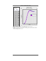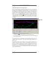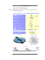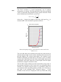
1
.. .. .. .. .. . Centre for Renewable Energy Sources 19th km Marathon Avenue GR-190 09 Pikermi, Greece Τel: +30 210 66 033 00 e-mail: [email protected] http://www.cres.gr/windrose A wind data analysis tool . . WindRose . . . . . . . User’s Guide N NNW NNE NW NE WNW ENE W E WSW ESE SW SE SSW SSE S Document version: 8.1 Excel COM+ Add-In version: 3.88 Analysis DLL version: 5.89 . Table of Contents Introduction ............................................................................. 1 Installation ............................................................................... 3 Running the program Running WindRose for the 1st time ..................................... 4 Registration / Demo version ............................................... 5 The Input worksheets Input ................................................................................... 6 Multiple anemometers - vanes (within the same mast) ........... 9 PowerCurve ........................................................................ 13 Quick Check of data ............................................................. 15 The Output worksheets Results ................................................................................ 16 Windrose ............................................................................ 20 Shear................................................................................... 21 AnnexK .............................................................................. 25 TimeCharts ......................................................................... 26 Tables ................................................................................. 27 3D ....................................................................................... 28 12pie, 12diurnal.................................................................. 29 BarCharts, Weibull ............................................................. 30 UhourT, UhourG, DIRhourT, DIRhourG ........................... 32 WTprodT, WTprodG.......................................................... 33 TempT, TempG, SRadT, SRadG........................................ 34 TempData ........................................................................... 35 Correlation –Prediction of missing data – MCP method WindCorr worksheet........................................................... 36 Methodology ...................................................................... 38 Appendix Advanced Options .............................................................. 45 Air-density variation with Height....................................... 47 Weibull distribution methods ............................................. 49 Power Curve correction ...................................................... 52 Installation issues WindRose.XLS Security warning....................................... 53 References ............................................................................... 55 WINDROSE : Wind Data Analysis software INTRODUCTION WindRose is a software tool dedicated to the analysis of wind characteristics (speed, direction, turbulence, temperature). It is not a standalone program, but an Add-In to the Microsoft Excel® 2000/XP/2003/2007, for the Windows 9x/ME/NT4/2000/XP/Vista/7 operating systems. The analysis results are stored graphically and numerically into spreadsheets, which can be further used as ordinary Excel files. The program is designed to provide all the results of the data analysis, in a customisable form to meet any particular needs. Thus, the user can rearrange all the graphs, resize them, change their colours, copy or link them to other sheets or programs (i.e.: embedded links to Microsoft Word® document), create new tables using the numerical results, etc. Data analysis complies with the requirements imposed by the IEC and MEASNET standards. Main features • It performs complete statistical analysis of the wind data, including Weibull distribution constants (per direction sector and global), turbulence intensity evaluation and polar plots (wind roses) of the time and energy distribution of the wind. • It correlates data from two sites calculating correlation coefficients globally and per ranges of wind speed and direction. As a result, it provides the predicted time-series for the missing data of a site, based on the other site’s complete set of data (MCP method). • Where multiple anemometers and/or wind vanes are present, the vertical wind shear is calculated (per wind speed and per direction sector). Thus, the extrapolation of the wind speed at higher heights (ie: hub height of a wind turbine) is performed more accurately. • A dozen of power-curves from a variety of wind turbines are included, providing a good estimate of the expected energy production. PAGE 1 WINDROSE : Wind Data Analysis software • It has a user configurable time step (10 minutes, 1 hour, etc) and it is able to analyse huge data sets (limited only by the available computer memory). • In case of measurements with systematic errors, a linear correction can be applied for all the measured quantities and separately for each file. • It includes 3 methods for the air-density correction (due to the site elevation height and to the temperature), which is critical for the correct calculation of the wind energy. • It produces monthly charts and tables with the per hour variation of wind speed, wind direction, expected wind turbine’s power, temperature and solar radiation. How it works WindRose reads ASCII files containing columns of data, an output format supported by the majority of data-loggers. Five 1 columns of data are necessary for the program to run: wind speed, wind direction, standard deviation of the wind speed, time and date. Several formats are supported when dealing with date and time. Whenever temperature atm. pressure, humidity, solar radiation, flow inclination are recorded, the appropriate analysis is performed. 1 If the wind speed’s standard deviation is not recorded, the program can still run, using the following trick: provide the same column numbers for both U (wind speed) and Usdv and then ignore the Turbulence Intensity results (which will be constant to: 100%). PAGE 2 WINDROSE : Wind Data Analysis software INSTALLATION Assuming that Microsoft Excel is properly installed, WindRose can be installed using the SETUP.EXE program. Administration privileges are required in Windows NT4/2000/XP. At the end of the installation, the WindRose option is added in the main menu of the Excel (Figure 1). By opening the WindRose.XLS file (default location: c:\Program Files\WindRose), you are ready to run the program for the first time (see below RUNNING THE PROGRAM). Running WindRose within Excel. Digital Signature Microsoft Excel has security levels that allow users to run macros based on whether or not they are digitally signed by a trusted macro developer. The WindRose.XLS file includes some macros and has a digital signature named WindRose. The first time that the WindRose.XLS file is opened, the user is asked whether or not the macros should be enabled. Answer yes so that WindRose runs properly and never asked in the future the same question. If you are not allowed to open the WindRose.XLS file with the included macros enabled (might happen if the Security Level of Excel is set to: High), then consult the Appendix: INSTALLATION ISSUES. PAGE 3 WINDROSE : Wind Data Analysis software RUNNING THE PROGRAM Running the program for the first time Three sample data files (ST-FLASH.TXT, NOMAD.TXT and GenASCII.TXT) containing wind data are included in the package to facilitate the first run of the program. Moreover, the Input worksheet contains already, all the required information to run the wind data analysis for the specific data files. All the user has to do is, to select from the Excel Main Menu, “WindRose” and then, “Run” 2 . The status bar of the Excel should then display the different steps of the program’s execution3 . At the end, the results of the analysis are stored in forms of graphs and/or tables into the different worksheets. Before calculating the correlations/predictions between 2 sites, WindRose has to be run twice, once per each site. The WindRose Excel workbook is composed by the following 24 worksheets: 1. 2. 3. 4. 5. 6. 7. 8. Input PowerCurve Results WindCorr Tables Weibull Upolar UhourG 9. UhourT 10. TimeCharts 11. 3D 12. 12diurnal 13. 12pie 14. BarCharts 15. WtprodG 16. WtprodT 17. 18. 19. 20. 21. 22. 23. 24. DIRhourG DIRhourT TempG TempT SradG SradT TempData Air-Density Two worksheets (Input and PowerCurve) are used for defining all the necessary parameters to run the program. The remaining worksheets are used for presenting graphically and numerically the results of the analysis. The content of all the worksheets is explained in detail in the following paragraphs. Note • When working with the original WindRose.XLS, keep it unchanged for future use, by saving it at the end of the analysis (using the Save As… option) with another name. If the default program path: c:\Program Files\WindRose was changed during the installation, then modify accordingly the paths of the 3 provided sample files in the Input sheet. 2 During the program execution and under certain circumstances, the PC may not respond for a few seconds. 3 PAGE 4 WINDROSE : Wind Data Analysis software Demo version Registration The demo version of the WindRose (for unregistered users) incorporates all the features of the full version, but is limited to analysing measured data that do not exceed 31 days. Registered users are given a code, which is entered using the WindRose menu within Excel. If the PC’s OS is Windows Vista, then before entering the code, turn off the User Account Control (Control Panel, Security Center) and turn it back on afterwards. Import OLD WindRose.XLS files Excel files created with older versions of WindRose, can be imported using the “Import…” option of the WindRose menu (see figure below). Regarding older files, this version of WINDROSE.XLS has some new input parameters and graphs, therefore some graphs and tables may not display correctly. PAGE 5 WINDROSE : Wind Data Analysis software THE INPUT WORKSHEETS Input Four tables compose this worksheet, which deals with the input data and the necessary parameters required by the program. The first table contains the names of the ASCII files to be read together with the column numbers of the requested quantities (wind speed, direction etc). The number of the lines to skip in the beginning of each file, containing blank lines or comments is also given here. Multiple data files can be specified by using wildcards (*, ?) in their names. If the order of the files is not the chronological one (from older to newer data), then sorting of data is performed automatically without any user action. However, additional memory is needed for that. Some of the columns of the ASCII data file can be assigned as control signals, enabling thus data filtering depending on e.g.: the data logger’s battery level, the rain, the signal quality of Lidars (CNR for Windcube, points in fit for ZephIR), etc. The acceptable range of each control signal can be assigned in WindRose’s Advanced Options… menu. Note that wildcards (* and ?) are accepted to specify multiple files File names and column numbers (sheet Input). Delimiting characters (within the ASCII data files) It is expected that ASCII files contain some comment lines in the beginning, followed by at least 5 columns of data. The accepted characters delimiting (separating) the columns are the following: • The space • The comma (,) • The semicolon (;) • The 2 parentheses • The tab • The double quotation marks (“) PAGE 6 WINDROSE : Wind Data Analysis software Time format WindRose accepts as time format, when reading ASCII files, the following forms: hh:mm:ss , hh.mm.ss , hhmmss , hh:mm , hh.mm , hhmm Note that, if none of the delimiting characters: : . are present and 5-6 digits are found then, the last two represent the seconds, the middle two the minutes and the first one(s) the hour. If 3-4 digits are found then, the last two represent the minutes and the first one(s) the hour of the day. Finally, if just 1-2 digits are found, then depending on the time step they are considered either as minutes, if the time step < 1h (i.e.: 5 is taken as 00:00:05), or as the hour of the day, if the time step ≥ 1h (i.e.: 5 is taken as 05:00:00). Other custom formats i.e.: the 12-hour form using am and pm (i.e.: 1:50pm) and the French-style h (i.e.: 13h50) can be supported on demand. Finally, there are cases where time comes in the form of incremental steps from the beginning of the day. Thus, the time column is filled with integers increasing from 1 to 144 (time step=10min) or from 1 to 1440 (time step=1min) etc. In this case we add the character s right after the column number. For example if the time column was the 9th we put 9s. Date format WindRose defaults to the European date format, but also accepts other date formats. If the date has one of the following (European) formats, then it is directly read. ddmmyy , ddmmyyyy , d/m/yy , dd/mm/yyyy dd.mm.yyyy , d-m-yy , dd-mm-yyyy , d.m.yy , The acceptable delimiting characters for the date format are: / . - . If the American format is used (mm/dd/yy, mmddyyyy, etc) then, right after the column number of the date, we put the character u i.e.: for the 10th column we write 10u. If the “international” date format is used (yymmdd, yyyy.mm.dd, etc) then after the column number of the date, we put the character i i.e.: for the 10th column we write 10i. Measurements data coming from the NOMAD data logger use another date format. I.e.: for the 26th September 1998 it is written: PAGE 7 WINDROSE : Wind Data Analysis software Sep 26, 1998 When reading such files, the above sequence should be considered as one column (instead of 3). Additionally, right after the column name we put the character n i.e.: for the 10th column we write 10n. Some models of the CAMPBELL data loggers use another particular date format: An integer number is given indicating the number of days elapsed from the beginning of the year. Thus, for the 26th September 1998 it is written: 1998, 269 This case is treated by adding the letter c right after the date column number i.e.: for the 10th column we write 10c However, the daycolumn: i) has to be next to the year column (i.e.: 11th in the previous example) ii) should not be the file’s last one and iii) is normally counted when numbering the columns of the ASCII file. PAGE 8 Date Lines to skip Lines to skip 2 4 5 6i Lines to skip Time 3 Date 2 Gust of Wind Speed [m/s] 1 5 6u 4 Date Intentionally (for better understanding), the first lines of the date and time columns contain various format types. 4 2 Time Date -------00/12/01 00/12/1 0/12/1 6 Time Time -----0:7 0:17:00 0:27:00 Solar Radiation (W/m2) Gust ----22.7 21.9 21.1 5 Gust of Wind Speed [m/s] Usdv ---2.9 2.8 2.9 3 4 Gust of Wind Speed [m/s] Dir ----137.6 144.6 146.5 2 Temperature (°C) WindSpeed --------14.3 14.3 13.9 1 Solar Radiation (W/m2) Date -------12/01/00 12/1/00 12/1/0 12-1-2000 12.1.2000 12.1.00 12-1-2000 12/1/2000 12012000 12012000 12012000 12012000 12012000 Solar Radiation (W/m2) Time -----0:7 0:17:00 0:27:00 00:37:00 00:47:0 0057 0107 0117 1.27.00 1.37.00 1.47.00 015700 020700 Wind Speed SDV Gust ----22.7 21.9 21.1 22.7 21.1 20.4 20.4 19.6 21.9 21.1 20.4 20.4 21.1 3 Temperature (°C) Usdv ---2.9 2.8 2.9 2.9 2.7 2.6 2.8 2.5 3.2 3.0 3.0 3.0 2.5 2 Temperature (°C) Dir ----137.6 144.6 146.5 144.0 146.6 144.3 142.1 140.6 146.5 144.1 147.8 150.3 148.3 Wind Direction (°) WindSpeed --------14.3 14.3 13.9 14.1 13.4 13.1 12.4 12.6 12.8 12.4 13.2 13.3 12.8 1 Wind Speed SDV Date -------01/12/00 1/12/00 1/12/0 1-12-2000 1.12.2000 1.12.00 1-12-2000 1/12/2000 01122000 01122000 01122000 01122000 01122000 Wind Speed SDV Time -----0:7 0:17:00 0:27:00 00:37:00 00:47:0 0057 0107 0117 01.27.00 01.37.00 1.47.00 015700 020700 Wind Direction (°) Gust ----22.7 21.9 21.1 22.7 21.1 20.4 20.4 19.6 21.9 21.1 20.4 20.4 21.1 Wind Speed (m/s) Usdv ---2.9 2.8 2.9 2.9 2.7 2.6 2.8 2.5 3.2 3.0 3.0 3.0 2.5 Wind Direction (°) Dir ----137.6 144.6 146.5 144.0 146.6 144.3 142.1 140.6 146.5 144.1 147.8 150.3 148.3 Wind Speed (m/s) WindSpeed --------14.3 14.3 13.9 14.1 13.4 13.1 12.4 12.6 12.8 12.4 13.2 13.3 12.8 Wind Speed (m/s) Below, some examples are given showing how the Input sheet should be filled4 . 2 WINDROSE : Wind Data Analysis software 14.1 13.4 13.1 12.4 12.6 12.8 12.4 13.2 13.3 12.8 22.7 21.1 20.4 20.4 19.6 21.9 21.1 20.4 20.4 21.1 00:37:00 00:47:0 0057 0107 0117 1.27.00 1.37.00 1.47.00 015700 020700 2000-12-1 2000.12.1 00.12.1 2000-12-01 2000/12/01 20001201 20001201 20001201 20001201 20001201 SOMEWHERE 1 8 Multiple anemometers - vanes (within the same mast) c:\data\site1\st010604.000 21;17;13;9;5 33;29;25 22;18;14;10;6 37 Lines to skip Date 20;16;12;8;4 2 1 33 Multiple anemometers and vanes: Example form of Input sheet’s 1st table. Case with 5 anemometers and 3 wind vanes. PAGE 9 Time Solar Radiation (W/m2) Temperature (°C) File Names Wind Speed SDV Column Numbers Gust of Wind Speed [m/ When multiple anemometers and wind vanes are present, WindRose provides some additional results (i.e.: wind shear, Weibull distributions per height, etc). In that case, the column numbers of each device, should be separated by a semicolon ;. Furthermore, the heights of the anemometers should be set accordingly (in ascending order) in the 2nd table of the Input sheet. Lines to skip Date Time Gust of Wind Speed [m/s] Vane A Wind Van Average 10 minut ° -------222.2 222.2 222.2 226.4 227.8 226.4 236.2 250.3 253.1 251.7 3 11 4 Solar Radiation (W/m2) ----18:57 19:00 19:10 19:20 19:30 19:40 19:50 20:00 20:10 20:20 Anem A Anem A Anem A Other An Other An Other An Avg Dev Minimum Maximum 10 minut 10 minut 10 minut m/s m/s dir time m/s dir time -------- ---------------- ---------------1.2 7.9 236 18:59 11.6 211 18:59 0.8 9.4 221 19:05 13.2 219 19:04 0.7 10.6 226 19:17 13.4 224 19:19 0.7 10.0 225 19:22 13.1 228 19:25 0.7 9.6 228 19:31 12.4 219 19:30 0.6 9.1 225 19:44 12.0 233 19:49 0.8 9.1 243 19:54 12.7 245 19:59 1.0 8.4 277 20:04 13.0 250 20:06 1.2 8.2 246 20:15 15.8 245 20:18 1.2 9.8 250 20:21 14.3 246 20:25 Temperature (°C) ----------Mar 1,2000 Mar 1,2000 Mar 1,2000 Mar 1,2000 Mar 1,2000 Mar 1,2000 Mar 1,2000 Mar 1,2000 Mar 1,2000 Mar 1,2000 Anem A Other An Average 10 minut m/s -------10.1 11.5 12.2 12.1 11.2 10.9 10.8 10.4 11.4 12.3 Wind Speed SDV TIME minute(s) Wind Direction (°) DATE 3 Wind Speed (m/s) 18:57 03/01/2000 15:00 03/27/2000 25 day(s) 20 hour(s) Wind Direction (°) Start Time: Finish Time: Total Time: 2.9 2.7 2.6 2.8 2.5 3.2 3.0 3.0 3.0 2.5 Wind Speed (m/s) Site Name: Site Number: 144.0 146.6 144.3 142.1 140.6 146.5 144.1 147.8 150.3 148.3 2 1n 13 WINDROSE : Wind Data Analysis software Measurements Height : above Ground level (m) 10;20;30;40;50 Setting the corresponding anemometers heights (Input sheet’s 2nd table). In this example the 21st column contains the wind speed at 10m height. The second table of the Input sheet contains all the necessary parameters characterising the analysis to be performed. These parameters are: • The measuring period (start and end dates) • The time interval of the measurements (10 minutes, 1 hour, etc) • The limit for the calm, which is the value of the wind speed below which the response of the wind direction measuring device is not reliable (recommended value: 2m/s) • The number of the direction sectors (16, 12 or 8) that the program will use (recommended value: 16) Title1 Title2 ( Site's name ) ( comment ) Start from End at 18/12/1999 29/5/2000 Minutes between data Limit for calms (m/s) Number of Direction Sectors 10 2 16 Measurements Height : above Ground level (m) above Sea level (m) 10 300 Calcul. of mean turbulence at wind speed (m/s) ± bin width (m/s) 10 1 Wind Turbine selected Exponent coefficient (α) NEG Micon Tacke 600 750/48 0.08 Weibull method low limit (m/s) high limit (m/s) 4 16 "paper" method Wind Speed Uncertainty Calibr. error at Umean (m/s) 0.06 Anemometer's max speed m/s 40 Data Logger's precision (bits) 8 Site Correlation file name Export processed data file name The necessary parameters for the wind data analysis (sheet Input) PAGE 10 WINDROSE : Wind Data Analysis software • The wind turbine for which energy calculations will take place. • The exponent coefficient of the Power Law, which is used to extrapolate the Mast’s wind speed at the Hub height of the wind turbine. This coefficient is used only when one anemometer is present on the Mast. If two or more anemometers are present, then this coefficient is calculated analytically (per wind speed bin and direction sector, more details in § SHEAR). The given value refers to 5m/s. Since it is not realistic to consider a constant value for the entire wind speed range, a simple model is used to “expand” it: every 5m/s this value is divided by two. Thus, if 0.08 is set, then at 10m/s is 0.04, at 15m/s is 0.02, etc. A linear regression is used for the intermediate values and the double of it is considered at 0m/s (0.16 in the above example). • The Weibull distribution calculation method. In brief, 2 methods are proposed for the calculation of the (k, C) coefficients: a) using only the mean and the standard deviation of the wind speed and b) using the data distribution, restricted or not to a specific range (i.e.: 4-16m/s).5 The second method is recommended. More details can be found in the Appendix § WEIBULL DISTRIBUTION. • The wind speed uncertainty in case of analogue anemometers (i.e.: the output signal of the anemometer is analogue voltage). These parameters are not used in case of anemometers producing pulses/revolution.6 • The name of the (intermediate) file that must be created when site correlation will take place (details in the CORRELATIONS chapter). • The name of an ASCII file into which all the row data are exported. This is particularly useful when delivering long term data (i.e.: yearly) that are stored originally in many files and/or to which correction coefficients were applied7 . 5 The 2 values below the selected Weibull calculation method are taken into account only if the 2nd method is selected. Uncertainty calculation for “pulsed-ouput” anemometers will be added in the next program release. 6 The created export file includes all the corrections, so no corrections should be applied if it is further processed. 7 PAGE 11 Time OFFSET (sec) Time MULT Solar Radiation MULT Temprature OFFSET (°C) Temperature MULT Wind Direction OFFSET (°) Wind Direction MULT Wind Speed OFFESET (m/s) Wind Speed MULT Correction Coefficients Solar Radiation OFFSET (W/m2 WINDROSE : Wind Data Analysis software -38 600 A sample of the correction coefficients table (sheet Input). The third table of the Input sheet includes correction coefficients per each file. The correction applied has the form: α·x+β and is intended for the processing of measured quantities, when: 1. A systematic error occurred during the measurements campaign (i.e. wrong calibration factors, additional offset for the “zero” of the wind vane, etc) 2. Recorded data have different units (temperature in Fahrenheit degrees, wind speed in miles/h, wind direction in radians, etc…) If no values are given, then the multipliers α and the offsets β are set to 1.0 and 0.0 respectively. The following important issues have to be pointed out when applying correction coefficients: • If the wind speed has to be adjusted by means of the correction coefficients (y=α·x+β), then its standard deviation is automatically multiplied by the coefficient (α). • When adjusting wind directions, if the resultant direction angle falls out of the [0°, 360°] interval then, is automatically adjusted. • Applying correction coefficients on the time/date should be done with caution. Although, there is no problem using the offset β (in seconds), in order to simulate a wrong day or time setting, the multiplier α (if ≠ 1.0), can seriously affect the reliability of the measurements, as it modifies the sampling rate (time step) of the measurement campaign. The fourth table of the Input sheet deals with the calculation method of the air-density, which seriously affects the wind energy calculations. If data contain time-series of atmospheric pressure and temperature, PAGE 12 WINDROSE : Wind Data Analysis software then this table is not used, since the air density is calculated from real data complying with IEC-61400-12. In the opposite case, three are the possible choices: • The “first method” uses an empirical formula relating air-density only to the anemometer elevation (site height + anemometer height). • The “second method” calculates air-density using both the height and the temperature. Two additional values are required: the vertical temperature gradient Γ (recommended value: 6.5ºC/km) and the estimated mean ground temperature (for the measurements period). If temperature data exist into the data files, then the recorded mean value is used instead. • The “third method” uses 12 preset values, one per each month of the year. These values can be retrieved either from a nearby meteorological station or set intuitively. The mean value of the air density used during the calculations is given in the Results sheet. More details on the air-density calculation methods and on the power curve corrections are given in the Selection of the method for the Air Appendix. Density correction. Power Curve Pairs of columns, containing power curves of various wind turbines, compose this worksheet. Some representative power curves are included by default, but the user can add more or delete the existing ones. One restriction applies here: The user has to respect the form of the existing power curves (i.e. put in the Row1 cell the model name of the wind turbine, in the Row2 cell of the next column the tower height, choose the power control strategy, etc.). Note • A linear interpolation is performed in order to calculate the exact electrical power of the wind turbine, between the given values of the power curve. • Whenever the measured wind speed is lower than the minimum value or greater than the maximum value of the power curve’s wind speed then, the power is considered as zero and the wind turbine as out of operation. PAGE 13 WINDROSE : Wind Data Analysis software NEG Micon 750/48 tow er=45m, control:stall 800 700 600 Ref . Power Curv e Correction applied 500 Power (kW) NEG Micon 750/48 tower (m): 45 diameter(m): 48 control: stall U (m/s) Power (kW) 3 0 4 19.5 5 53.1 6 97.4 7 155.3 8 244.6 9 349.2 10 462.2 11 564.5 12 640.5 13 696.3 14 729.8 15 745.5 16 750 17 744.6 18 734.8 19 723 20 711.9 21 701.4 22 694.3 23 692.8 24 695.2 25 700.6 400 300 200 100 0 0 5 10 15 U (m /s) 20 25 30 Left: A sample of a power curve table (sheet PowerCurve). Right: Its graphical representation including the correction due to the site elevation height (sheet Input) PAGE 14 WINDROSE : Wind Data Analysis software QUICK-CHECK OF THE DATA Once the input sheets are filled correctly, the user can launch the WindRose by selecting Run in English or Run in Greek depending on the language in which the results will be displayed. Execution time depends on the amount of data; normally a Pentium-4 PC will take ½ minute to run 1-year data. When the execution is finished the figure below will appear displaying all the processed valid data. This is an important feature of the program, since Excel graphs cannot contain unlimited amount of data and the user interaction (zooming, scrolling) is limited. Select part of the data for detailed view. Detailed view of all the processed data. Note that: a) zoom operation is possible by selecting a region with the mouse b) scrolling (panning) is achieved by holding the mouse down and dragging it to the desired direction. An experienced user will find this screen particularly useful, as he can quickly deduce the quality of the data (spikes, fault operation of a device, etc.). Displaying a smaller data “window” is also possible when the View Mode is set to: Zoom X & Y (or Zoom X if zooming is done only in the time axis). When a smaller data “window” is displayed, the user can smoothly move forward or backward, by selecting Pan X & Y (or Pan X just for the time-axis) and holding down the mouse while dragging it to the desired direction. PAGE 15 WINDROSE : Wind Data Analysis software THE OUTPUT WORKSHEETS Results This one page sheet presents the summary of the performed analysis. The displayed quantities are: Measurements Period : from 4/2/2002 to 3/2/2003 Mean Annual Wind Speed (at 40m height) 6.2 9.2 27.2 34.1 0.2 307.8 2477.1 Mean Turbulence Intensity (at 10m/s) Max. 10min Average Wind Speed Maximum Gust Uncertainty of Wind Speed measurement Mean Wind Power Total Wind Energy Weibull Distribution constants shape factor (k) scale factor (C) m/s % m/s m/s m/s Watt/m² kWh/m² (general mean= 6.0 m/s) (6/1/2003 07:50) (6/1/2003 07:40) 1.62 6.7 m/s Total number of valid data Included number of calms (<2m/s) Missing data 48280 5593 4280 (8.1% ) Expected W.T. energy production W.T. Capacity Factor Calc. Annual Mean Wind Speed at 67m height 3 740 376.3 kWh 23.2 % 6.6 m/s (general mean= 6.5 m/s) WT Annual Energy Production & cap. factor calculated from data distribution calculated from Weibull distribution 4 157 412.3 kWh 4 121 376.8 kWh 23.71 % 23.51 % Best Sector in Energy contain 2nd best Sector in Energy contain Best Sector in Time distribution 2nd best Sector in Time distribution NNW SSE NNW SSE 41.22 % 20.64 % 29.95 % 23.59 % Mean Wind Speed variation Main Directions NNW 10 NNW N (Gamesa G80-2.0MW (ρave=1.148kg/m3) NNE WNW NNE 8 NW NE NW N NE 6 ENE 4 WNW ENE 2 W E WSW 0 W E ESE SW WSW SE SSW S ESE SW SSE SE SSW SSE S Time Distribution % % >15m/s % % 10-15m/s % 5-10m/s % 2-5m/s % % N NNW NW WNW W WSW SW SSW S SSE SE ESE E ENE NE The main results of the WindRose program (worksheet: Results). PAGE 16 NNE WINDROSE : Wind Data Analysis software • The mean wind speed. Note that, if more than 1-year data exist then, apart from the mean value of all the wind speed data, the “annual mean” is also provided. The calculation method of this value (see § below) assures that nonstationary effects, such as seasonality, are not taken into account. • The turbulence intensity (at the specified wind speed range). • The maximum wind speed and the date of its occurrence • The maximum gust (1sec value) and the date of its occurrence (if a gust column was set in the Input sheet). • The mean power of the wind per area (in units of kW/m2). • The total wind energy per area (kWh/ m2). • The coefficients of the Weibull distribution that fits all the data. • The total number of valid data within the specified time period (by the Start-Stop dates given at the Input sheet) • The percentage of the missing data. • The number of calms (wind speed below a threshold) • The expected electrical energy production (kWh) of the selected wind turbine during the given period of measurements, for all the valid data. • The capacity factor of the wind turbine (percentage of the nominal power of the wind turbine, at which the machine should operate continuously to produce the expected electrical energy) • The estimated mean wind speed at the nacelle height of the wind turbine. Similarly with the measured mean wind speed, if more than 1-year data exist, then the given value is the average of 12 monthly values. Each monthly average value is weighted with the completeness of the given month for all the years. • The expected Annual Energy Production (AEP) in kWh and the corresponding capacity factor. Both are calculated by two methods: a) from the data distribution and b) from the Weibull distribution. If 12-month data exist, then the AEP is calculated from the 12 distributions. In the opposite case (less than 1-year data), the AEP is calculated from the general average distribution. • The two best direction sectors in wind energy contain. • The two best direction sectors in terms of time. PAGE 17 WINDROSE : Wind Data Analysis software Note that, the “annual mean” wind speed calculation takes into account the various data completeness of each month, during all the years of measurements. Averaging the 12 months, assures that the result a) represents the 1-year reference period and b) is not biased by data that fail to cover exactly 12, 24, 36, etc months. Below, an arithmetic example is given, representing the described procedure. STEP 1 Month --------Jan. 2003 Feb. 2003 Mar. 2003 Apr. 2003 May 2003 Jun .2003 Jul. 2003 Aug. 2003 Sep. 2003 Oct. 2003 Nov. 2003 Dec. 2003 Jan. 2004 Feb. 2004 Mar. 2004 Apr. 2004 May 2004 Jun. 2004 STEP 2 Mean Data Wind Speed Complet. -------- ---------9.3 100 % 7.0 100 % 6.9 100 % 6.3 60 % 5.3 100 % 6.9 100 % 7.7 99 % 8.5 90 % 6.0 100 % 6.4 100 % 8.1 100 % 7.9 75 % 10.9 54 % 8.3 98 % 6.3 100 % 8.0 100 % 7.3 100 % 5.9 82 % Month ----Jan. Feb. Mar. Apr. May Jun. Jul. Aug. Sep. Oct. Nov. Dec. Mean Data Wind Speed Completeness ----------------------9.86(*) 77 % 7.64 99 % 6.6 100 % 7.36 80 % 6.3 100 % 6.45 91 % 7.7 99 % 8.5 100 % 6.0 100 % 6.4 100 % 8.1 100 % 7.9 75 % STEP 3 Mean Annual Wind Speed = 7.4 = ( 9.86+7.64+6.6+7.36+6.3+6.45+ +7.7 +8.5 +6.0+6.4 +8.1+7.9 )/12 (*)9.86 = (9.3*1.0+10.9*0.54)/1.54 Why 3 values for the expected W.T. Energy production? • The 1st value refers to the energy production of the wind turbine for the given time period, while the other 2 refer to the annual production. • The 1st value depends on the missing data, as it is calculated only by the valid data, within the given time-period. The other 2 values are the outcome of the projection of the 2 distributions (data and Weibull) to 1-year. Thus, the notion of missing data is not applicable to them. • If the given time-period (defined by the Start, Stop dates) is one year then, the 3 values should converge. In fact, if there is no missing data then, the 1st and the 2nd values should be practically the same. If the 3rd value is close enough to the other two, it means that the given Weibull distribution coefficients (k, C) fit PAGE 18 WINDROSE : Wind Data Analysis software well the data and can be used safely to characterize the site. • For the same reasons there are also 3 wind turbine capacitor factors. How the W.T. Energy production is calculated? • The wind turbine energy production is based on the wind speed estimation at hub height. If measurements are not taken at the WT’s hub height, then the wind speed is extrapolated to that height. For that, the “power law” is used in order to calculate the wind shear. • When the wind speed is measured at different heights, then the detailed wind shear (per direction and per wind speed) is calculated. If the wind speed is measured at only one height, then a uniform shear is assumed, based on the exponent coefficient α of the power law. • Having calculated the wind speed time-series at hub height, the energy production is evaluated using the “corrected” power curve. • Usually, the power curves given by the WT manufacturers refer to the sea level, where ρ=1.225kg/m3. Therefore, the air density at the specific site elevation needs to be evaluated (using 3 different methods, including or not temperature timeseries, etc). Finally, this local air density and the type of the power control of the wind turbine (i.e.: stall or pitch), provide the “corrected” power curve, according to the IEC-61400-12 recommendation. Two charts are shown below the results table: A pie chart presenting schematically the most prevailed directions of the site and a polar chart showing the variation of the mean wind speed as a function of the direction. Finally, the data distribution in time per direction sector is given. Each bar is composed by 4 parts, depending on the percentage of time that PAGE 19 WINDROSE : Wind Data Analysis software the wind speed at the specific sector falls in the 4 preset ranges8 : [2m/s-5m/s), [5-10m/s), [10-15m/s), [>15m/s). This sheet is composed by the total and the monthly wind roses (distribution chart in polar co-ordinates). They present the wind speed distribution (%) per direction, in the time and energy domain. WindRose May % energy N NNW NW WNW W 7 6 5 4 3 2 1 0 % time N NNE NNW NE 30 NW NE 20 ENE 15 WNW ENE 10 5 E 0 W WSW NNE 25 E ESE WSW SW ESE SE SSW SW SSE SE SSW S SSE S Samples of a site’s wind roses (total and monthly) Note that, for maximum precision, the polar plots are divided in 64 sectors, each 5.625° (=360°/64) wide. Each point of the drawn line, represents the mean value of all the data within this sector, i.e. the value of the distribution at 0° is the mean value of all the data found within the sector [-2.8125, +2.8125). It is reminded here that, in order to calculate both time and energy distributions per direction sector, only data with wind speeds greater than the calm limit (set in the Input worksheet) are taken into account. If the user wants to change this and take into account the total data, he has to set the calm limit to 0m/s and re-run the program. Finally, note that the energy refers to the energy of the wind, not the estimated electrical energy of the wind turbine. Although, in most of the cases the two distributions are identical, differences might exist in case of very high wind speeds (greater than the cut-out wind speed), where the wind turbine is supposed to shut down. 8 The low limit is actually the calm threshold value (as set in the Input sheet), below of which the response of the wind direction measuring device is not reliable. PAGE 20 WINDROSE : Wind Data Analysis software This Excel worksheet is created automatically only if multiple anemometers are present. The first graph shows the mean wind speed values (as measured) along with the average vertical wind shear. Wind shear calculations are based on the “power law”: α ⎛ z ⎞ ⎟ u ( z ) = u ( z ref ) ⎜ ⎜z ⎟ ⎝ ref ⎠ where the zref denotes the height at which the wind speed u(Zref) is measured and α is the wind shear exponent coefficient. Mean vertical wind profile 60 Height [m] Shear 50 6.7 m/s 40 6.6 m/s 30 6.4 m/s 20 6.2 m/s 10 5.7 m/s 0 0 2 4 6 8 Wind Speed [m/s] Mean wind speed per height – measurements & mean vertical shear (sheet Shear) The next table shows the measured mean and max wind speeds per direction and per height. At the end, the calculated values are given for the hub height of the selected wind turbine. The variation of the Weibull coefficients per height and per direction is given in another separate table. Both tables provide results at hub height, based on the extrapolated wind speed time-series at that height (from the higher anemometer) using the wind shear results. The last table of this worksheet presents in detail the average value of the exponent coefficient α of the “power law” per wind speed and per direction. For each time step one value of α is calculated. Values of α are considered valid, only if the goodness of fit R2> 0.95. Note that, a) this value is user selectable from “Advanced Options…” of the WindRose menu and b) it is displayed on the top of that table, along PAGE 21 WINDROSE : Wind Data Analysis software with the data percentage satisfying that condition, providing thus an indication of the validity of the Power Law at the specific site. R2 = 0.85 R2 = 0.975 Z Z U U Measured wind speed (black dots) and calculated wind shear: Goodness of fit criterion: Left: R2<0.95 rejected. Right: R2>0.95 accepted Average and Max (10min) wind speed per direction Height 10 20 30 U NNE ENE E ESE SSE S SSW WSW W WNW NNW N All Dirs Ave 6.84 5.59 3.62 3.19 4.37 5.35 5.04 5.07 4.76 3.88 6.06 6.98 5.75 Max 16.85 13.52 8.18 8.79 16.57 13.06 12.34 11.84 10.91 10.88 16.03 19.03 19.03 Ave 7.29 6.07 3.78 3.35 4.57 5.61 5.39 5.66 5.57 4.27 6.42 7.32 6.17 Max 17.58 14.48 8.86 9.17 16.75 13.15 13.11 13.68 13.39 13.27 16.55 19.50 19.50 Ave 7.72 6.52 4.07 3.24 4.64 5.70 5.77 6.10 6.04 4.49 6.51 7.45 6.44 Max 18.03 15.50 9.73 9.20 16.65 13.52 13.85 14.83 15.06 14.37 16.46 19.60 19.60 Ave 7.98 6.65 3.86 3.47 4.63 5.70 6.00 6.37 6.29 4.62 6.65 7.64 6.62 Max 18.27 15.78 9.80 9.52 16.30 13.84 14.56 15.15 15.54 14.43 16.67 19.85 19.85 50 Ave Max 8.00 18.37 6.65 15.82 4.39 9.84 3.50 9.42 4.59 16.18 5.67 13.92 6.07 14.88 6.51 15.55 6.46 16.02 4.72 14.83 6.74 16.94 7.67 20.04 6.69 20.04 80 Ave Max 8.41 18.85 7.03 16.62 4.60 10.41 3.60 9.60 4.66 16.06 5.77 14.24 6.45 15.87 7.03 16.86 7.08 18.04 5.01 16.25 6.96 17.25 7.90 20.33 7.02 20.33 40 Mean wind speed per height and per direction (sheet Shear) Weibull parameters per Height Height 10 20 30 40 Const NNE ENE E ESE SSE S SSW WSW W WNW NNW N All Dirs k 2.60 2.80 2.76 1.84 1.54 2.45 2.24 2.46 2.63 2.25 1.92 2.33 C 7.8 6.3 4.2 3.3 4.7 6.1 5.7 5.7 5.3 4.2 6.7 7.9 6.4 k 2.65 2.72 2.46 1.97 1.57 2.45 2.24 2.49 2.48 2.04 1.79 2.35 2.08 2.01 C 8.2 6.8 4.3 3.6 4.9 6.4 6.1 6.3 6.3 4.5 7.1 8.2 6.9 k 2.64 2.67 2.48 1.94 1.66 2.46 2.11 2.47 2.49 2.01 1.78 2.34 2.10 C 8.7 7.3 4.7 3.5 5.0 6.5 6.6 6.8 6.8 4.8 7.2 8.4 7.2 k 2.62 2.63 2.24 1.92 1.66 2.49 2.07 2.49 2.49 2.08 1.78 2.35 2.08 C 9.0 7.4 4.4 3.7 5.0 6.5 6.8 7.1 7.1 5.0 7.4 8.6 7.4 50 k C 2.59 9.0 2.62 7.4 2.63 5.1 1.96 3.8 1.66 5.0 2.48 6.4 2.05 6.9 2.45 7.2 2.51 7.3 2.10 5.2 1.76 7.5 2.33 8.7 2.09 7.5 80 k C 2.55 9.5 2.53 7.8 2.64 5.3 2.01 3.9 1.70 5.1 2.46 6.5 1.94 7.3 2.41 7.7 2.40 8.0 2.02 5.5 1.71 7.7 2.31 8.9 2.07 7.9 Variation of the Weibull distribution parameters, per height and per direction (sheet Shear) PAGE 22 (measured) (calculated) WINDROSE : Wind Data Analysis software 2 Wind Shear exp. coef. α m/s 5-6 6-7 7-8 8-9 9-10 10-11 11-12 12-13 13-14 14-15 15-16 16-17 17-18 18-19 19-20 20-21 21-22 22-23 23-24 24-25 25average NNE 0.045 0.079 0.049 0.068 0.090 0.104 0.093 0.103 0.100 0.109 0.110 0.097 0.099 0.081 ENE 0.138 0.100 0.179 E 0.207 0.223 0.249 Data percentage with R >0.95 : 90.25% ESE 0.365 0.388 0.401 0.369 0.411 0.351 0.344 0.344 0.369 SSE 0.159 0.130 0.161 0.186 0.167 0.180 0.211 0.250 0.185 S 0.175 0.144 0.099 0.113 0.095 0.120 0.108 0.129 0.124 0.129 0.120 0.122 0.144 0.186 0.221 0.088 0.139 0.227 0.371 0.181 0.135 SSW 0.218 0.160 0.090 0.100 0.097 0.113 0.110 0.081 0.109 0.119 0.090 0.088 0.035 0.093 0.074 0.104 0.017 WSW 0.242 0.188 0.162 0.118 0.176 0.168 0.147 0.166 0.178 0.156 0.100 0.170 W WNW 0.310 0.165 0.357 0.278 0.374 0.398 0.355 0.424 0.396 0.525 0.404 0.475 0.482 0.474 0.465 0.363 0.404 NNW 0.166 0.164 0.175 0.152 0.172 0.134 0.102 0.083 0.050 0.092 0.126 0.066 0.391 Wind shear exponent results per wind speed and direction. 0.391 0.124 N average 0.080 0.165 0.099 0.146 0.099 0.124 0.086 0.119 0.077 0.107 0.075 0.101 0.079 0.106 0.079 0.107 0.073 0.091 0.075 0.095 0.078 0.087 0.078 0.084 0.078 0.082 0.076 0.080 0.070 0.070 0.070 0.075 0.070 0.069 0.059 0.059 0.058 0.058 0.086 0.086 0.062 0.062 0.077 0.116 (sheet Shear) Here it is underlined that, internally, the above table is calculated also for each month and for each hour of the day. The reason is the significant variability of the exp. coefficient α with these two parameters. Thus, when calculating the wind speed at a higher height (ie: hub height), if such values of α exist (per hour, per month, per wind speed and per direction), then they are preferably used, rather than the (summarized) ones of the above table. A typical graph showing the diurnal variation of the exponent coefficient α with the hour of the day. Result from Lavrio site (worksheet: Shear). At the end of the Shear sheet, a series of polar graphs are created showing the influence of the mast tower “shadow” on the (lower) anemometers, assuming that the reference anemometer is installed on the top of the mast, where the wind flow is undisturbed, no matter the wind direction. This is achieved by plotting the wind speed ratios above a threshold (4m/s). PAGE 23 WINDROSE : Wind Data Analysis software Influence of the mast tower “shadow” on the (lower) anemometers. Polar plot of the wind speed ratio of a lower anemometer versus the top one (worksheet: Shear). In the above example, note that at ~300° the anemometers ratio falls around 0.5, providing valuable information about a) the exact orientation of the boom and b) the boom length sufficiency according to the standards. A less pronounced drop of the ratio is also observed, as expected, diametrically at ~120°. Comparison of anemometers and vanes mounted on the same Mast (worksheet: Shear). These graphs are automatically created for all the low anemometers in respect to the reference one, without any user interaction. However, PAGE 24 WINDROSE : Wind Data Analysis software since Excel cannot handle more that 32000 data per graph, an external graph library is used to create them in a form of a PNG picture. Consequently, these graphs cannot further customized, as other Excel graphs in WindRose.XLS. This Sheet is created only if multiple anemometers are present and sufficient data exist (ie: several months). Ideally, cup anemometers should be calibrated in a wind tunnel after the measurement period, in order to assure the accuracy of the measurements, during the entire measurement campaign. Another (inferior) possibility is to perform an in-situ comparison between the top and the control anemometer (usually 1.5m below the top one). This procedure is defined in the Annex K of the IEC-61400-12-1 standard. Briefly, the procedure can be summarized as follows: Data are filtered for a narrow direction sector and classified in bins of 1m/s. Then, a linear regression is performed between the two anemometers, using data from the initial 1-2 months. Finally, the regression results are applied to the last 1-2 months of the measurements and compared to the real data. In-Situ comparison of anemometers at 28.5m and at 30m ( wind direc tions : 3 4 8 .7 5 deg - 1 1 .2 5 deg ) E valuation period (regres s ion) from: 1 2 /1 /2 0 0 8 to: 8 /3 /2 0 0 8 A pplic ation period (deviation res ults ) from: 1 6 /1 1 /2 0 0 8 to: 1 1 /1 /2 0 0 9 Anemometer at 28.5m [m/s] 4 5 6 7 8 9 10 11 0 .3 0 12 13 14 15 16 y = 0.9618x + 0.3264 R 2 = 0.9992 0 .2 5 16 15 14 13 0 .2 0 12 11 0 .1 5 10 Squared Sum of Dev iations Comparison of anemometers 0 .1 0 9 8 7 0 .0 5 6 5 0 .0 0 4 4-5 5-6 6-7 7-8 8-9 9-10 10-11 11-12 12-13 13-14 14-15 15-16 Wind speed bin [m/s] The main result of the Annex K sheet PAGE 25 Anemometer at 30m [m/s] Squared sum of deviations [m/s] AnnexK WINDROSE : Wind Data Analysis software The main result of the AnnexK sheet is a (complex) graph with 4 axes. In the blue axes (x-top, y-right) the linear regression between the two anemometers is presented. In the green axes (x-bottom, y-left) the square sum of the systematic and statistical deviations per wind speed bin are plotted. The in-situ comparison is considered successful (and a recalibration of the anemometers is not necessary), if each bar remains lower than 0.1m/s. The examined condition can be written as follows: 2 ⎛σ ⎞ ΔU + ⎜ ΔU ⎟ ≤ 0.1m / s ⎝ N⎠ 2 where: ΔU = Utop – (α*Ucontrol+β) with (α, β) being the regression coefficients for the initial period and Ν the number of data per each wind speed bin (Ν≥3 10min data). The default and recommended parameters for this method are: i) select data from 6m/s to 12m/s ii) use intervals of 8 weeks for both the first and last part of the measurements and iii) apply the method to the main wind direction sector. However, these parameters can be modified within the “Advanced Options…” of the WindRose menu. Three important figures are presented in this worksheet, displaying the results of the wind data analysis in a “global” form. More detailed “views” of the results are presented in the next worksheets. Mean Daily Wind speed variation 25 Mean 20 Wind speed (m/s) Time Charts Max 15 10 5 0 20/2/93 12/3/93 1/4/93 21/4/93 11/5/93 31/5/93 20/6/93 10/7/93 Date Wind speed variation per day (mean & max. values) • The 1st one shows the evolution of the daily mean wind speed, as well as, the maximum wind speed occurred per day, for the given time-step (i.e. if 10minutes series are recorded, the maximum value is of course, not the instantaneous 1sec gust, but the maximum 10minutes wind speed occurred during this day). • The 2nd figure presents the Diurnal distribution. Actually, this is the distribution of the wind speed as a function of the hour of the day. All the data are taken into account here, independently of the wind PAGE 26 WINDROSE : Wind Data Analysis software direction. The Diurnal distribution per month is presented in the 12diurnal worksheet. Diurnal Distribution 8.2 Wind speed (m/s) 8.1 8 7.9 7.8 7.7 7.6 7.5 7.4 7.3 0 1 2 3 4 5 6 7 8 9 10 11 12 13 14 15 16 17 18 19 20 21 22 23 Hour of the Day Distribution of the wind speed per hour of the day. • Finally, the 3rd figure shows the mean wind speed per month. If more than a year period is examined, each monthly mean wind speed is calculated from all the corresponding months. Mean Monthly Wind Speed Variation over a year 12 Wind Speed (m/s) 10 8 6 4 2 Nov Dec Oct Sep Aug Jul Jun May Apr Mar Feb Jan 0 Month Mean wind speed variation per month. Tables Two very essential tables are presented in this worksheet. The 1st one shows the variation of the % turbulence intensity (σu/U*100) over the wind direction and the wind speed. The 2nd one shows the total data distribution over both wind speed and direction. The following points should be noted here: The “binning” of the wind speed is done in 25 steps of 1m/s, starting from the [0m/s, 1m/s), with the 26th one gathering all data higher than 25m/s. The table of the turbulence intensities does not show the first five velocity bins (the Excel’s “Hide cells” option is enabled), as no physical meaning can be extracted from turbulence intensities, when the mean wind speed approaches to zero. In that case, the ratio σu/U takes very high values, dominating the rest ones in the graphical representation of the table (see worksheet:3D). PAGE 27 WINDROSE : Wind Data Analysis software Data distribution vs Wind Speed & Wind Direction m/s NNE 32 0-1 41 1-2 31 2-3 16 3-4 9 4-5 18 5-6 7 6-7 7-8 1 8-9 9-10 10-11 11-12 12-13 13-14 14-15 15-16 16-17 17-18 18-19 19-20 20-21 21-22 22-23 23-24 24-25 25totals 155 NE ENE 61 50 55 80 49 69 27 61 5 18 8 11 2 1 207 290 E 78 142 187 139 60 33 14 15 10 7 5 4 10 4 5 4 8 10 12 4 1 752 ESE 124 141 239 206 167 139 144 115 69 46 31 46 23 16 14 6 6 6 1 1 1540 SE 100 175 255 215 209 243 218 265 168 184 218 205 211 191 122 86 93 58 37 18 18 8 1 3298 SSE 92 134 140 127 158 220 218 204 122 78 77 71 81 37 34 27 26 12 7 11 8 6 4 2 3 1 1900 S SSW 154 110 158 158 141 139 153 161 189 142 148 105 130 91 54 91 31 93 28 52 26 42 19 23 26 26 23 20 13 15 4 2 6 3 2 1 SW WSW 104 141 224 315 304 483 361 720 284 899 236 609 208 430 177 246 138 151 135 122 83 76 71 72 61 30 33 22 51 6 63 3 22 8 2 1309 2565 1270 W WNW 189 229 436 493 782 784 1338 797 2165 862 2351 782 1988 1004 1463 1131 1272 1298 995 1413 1163 1439 1159 1338 1004 1245 938 1238 813 1100 430 933 162 684 29 524 6 470 1 308 189 89 25 5 3 4325 18684 18383 NW NNW 166 38 337 47 428 64 288 18 106 10 65 22 88 10 106 5 120 137 1 176 250 1 177 1 57 2 44 1 40 1 58 2 30 11 11 3 2698 223 totals N 36 42 22 7 7 13 3 1 2 1704 2978 4117 4634 5290 5003 4556 3873 3475 3198 3336 3259 2895 2581 2218 1599 1067 680 548 354 220 103 30 7 6 1 133 57732 Tables worksheet: Data distribution per wind speed and direction. The number of the wind direction sectors is the one selected in the Input worksheet (8, 12 or 16). As mentioned before, each direction refers to the mean angle of the corresponding sector. For example: suppose that 16 sectors are selected (the default and recommended value), then the width of each sector is 22.5° (=360°/16) and the North winds are all whose angle falls into the [348.75°, +11.25°) sector. The mean turbulence intensity, per wind speed and direction bin, is calculated using the classical averaging methods; no correction takes place. Although not precise, this simple method provides a satisfactory approximation of the “true” turbulence intensity, which could be calculated, only if the detailed wind speed time-series were available. The number of successive rotations of the wind vane (clockwise and counter clockwise) is given in the 2nd table. These revolution numbers, indicating the number of times that a wind turbine would have been rotated around itself, provide a good estimate of the number of times that the electrical power cables are twisted. For this calculation, all the data (including calms) have been taken into account, considering that even during low wind speeds, the wind turbine usually rotates for an optimum orientation. Obviously, the accuracy of the two numbers depends on the data completeness (low number of missing data). 3D This worksheet contains the 3D graphical representation of the Tables worksheet, showing the turbulence intensity distribution per wind speed and direction, as well as, the total data distribution again per wind speed and wind direction. PAGE 28 WINDROSE : Wind Data Analysis software Turbulence Intensity (%) vs Wind Speed & Wind Direction 35 30 25 20 15 10 5- 6 5 9- 10 0 13- 14 17- 18 21- 22 NE NNE ENE E ESE SE SSE S SSW SW WSW W WNW NW NNW N Turbulence intensity per wind speed and direction (3D worksheet). 12pie In this 2-page worksheet 12 pie charts are plotted, one per month of the year, showing the two dominant wind directions. At the end of the 2nd page a table is also given with the numerical representation of the figures. In case that, a prevailed sector (referring to time) is not among the best two sectors (referring to energy) then a blue colour is used (or a green colour in the opposite case). As in the WindRose sheet, the calms are not included here too. January NNW N February NNE NNW NE NW NW ENE N NNE NE NW NW ENE E W E W ESE WSW ESE WSW SW SSW SE S SW SSW S SSE SE SSE Main wind directions (blue: based on the time, green: based on the energy content). 12diurnal This one-page sheet is composed by 12 bar-plots presenting the Diurnal distribution of the data, per month of the year (all years included). In fact, it is the hourly variation of the wind speed per month, all the directions taken into account. Note that, if the total diurnal distribution is needed, it can be found in the TimeChart sheet. PAGE 29 WINDROSE : Wind Data Analysis software Important Note • If data exceed 1-year period the (monthly) graphs cumulate data from different years. When it is necessary to see the diurnal distribution of only one specific month, then the program should be run, once per year (specifying accordingly the start and end dates in the Input worksheet). March 10 8 6 4 2 Mean Wind Speed: 6.7m/s 12 Wind speed (m/s) 12 Wind speed (m/s) April Mean Wind Speed: 8.6m/s 0 10 8 6 4 2 0 0 2 4 6 8 10 12 14 16 18 20 22 0 2 Hour 4 6 8 10 12 14 16 18 20 22 Hour Example of the Diurnal distribution per month (12diurnal worksheet). Bar Charts The 4 most common representations of the wind distribution are plotted in the present worksheet. The first two show the distribution of the wind, based on the energy (not the expected energy production of the wind turbine) as a function of the wind direction (1st one) and the wind speed (2nd one). The last two show the time-based distribution of the wind as a function of the wind direction (3rd one) and the wind speed (4th one). Energy Distribution vs Wind Speed 700 Energy (kWh/m²) 600 500 400 300 200 100 0 1 2 3 4 5 6 7 8 9 10 11 12 13 14 15 16 17 18 19 20 21 22 23 24 25 Wind speed (m/s) Wind energy distribution versus wind speed. (BarCharts worksheet). Weibull The main figure of this worksheet shows the Weibull distribution that fits the wind data. All the wind directions have taken into account when calculating the shape (k) and the scale (C) coefficients of the Weibull distribution in this graph. If multiple anemometers are present, the graph refers to the reference anemometer (usually the highest one). PAGE 30 WINDROSE : Wind Data Analysis software 0.1 Data Distribution 0.09 Weibull Distribution (1.90, 9.0) 0.08 0.07 0.06 0.05 0.04 0.03 0.02 0.01 0 1 2 3 4 5 6 7 8 9 10 11 12 13 14 15 16 17 18 19 20 21 22 23 24 25 Wind speed (m/s) Data distribution together with the calculated Weibull distribution that fits the data. Some important information is included in the table below the graph. Here, the coefficients of the Weibull distribution are displayed per wind direction sector together with the corresponding percentage of the total data found in it, the mean wind speed, the turbulence intensity and the starting and ending values of the direction sector. Some thirdparty programs, dealing with optimum wind turbine arrangement within a wind farm (i.e.: WindFarm® by ReSoft), require as an input this table’s data, as well as, the site’s topography. Direction Angles (deg) Weibull shape Weibull scale Data Distrib Mean Wind Speed (m/s) NNE NE ENE E ESE SE SSE S SSW SW WSW W WNW NW NNW N 11.25 - 33.75 33.75 - 56.25 56.25 - 78.75 78.75 - 101.25 101.25 - 123.75 123.75 - 146.25 146.25 - 168.75 168.75 - 191.25 191.25 - 213.75 213.75 - 236.25 236.25 - 258.75 258.75 - 281.25 281.25 - 303.75 303.75 - 326.25 326.25 - 348.75 348.75 - 11.25 1.65 1.79 1.65 1.42 1.70 1.87 1.72 1.58 1.71 1.85 2.16 2.36 2.11 1.74 1.53 1.55 3.27 2.73 2.97 5.69 6.28 9.37 8.40 5.88 6.11 7.23 6.07 8.98 11.32 7.25 4.37 3.02 0.27% 0.36% 0.50% 1.30% 2.67% 5.71% 3.29% 2.27% 2.20% 4.44% 7.49% 32.36% 31.84% 4.67% 0.39% 0.23% 2.5 1.9 2.2 4.0 5.0 8.3 6.9 4.7 5.1 5.9 4.9 7.8 10.2 6.7 3.0 2.3 T.I. (%) at 10m/s 11.0 9.5 9.3 10.3 14.2 15.4 15.2 14.0 11.7 8.8 8.6 12.1 Weibull distribution coefficients, data percentage, mean wind speed and turbulence intensity, per direction sector. In this version of WindRose, the calculated Weibull coefficients per month are given only as values at: TempData!M109:O122 however, future versions will include a graphical representation. The 2nd graph of the worksheet is the wind data accumulated probability (based on the data distribution, not on the Weibull distribution). It is a useful tool to estimate the percentage of the time that the wind speed exceeds a specific value, i.e. how much of the time the wind speed exceeds the cut-in or the cut-out speed of the wind turbine. PAGE 31 WINDROSE : Wind Data Analysis software Cumulative Probability (%) 100 Cumulative Probability (%) 90 80 70 60 50 40 30 20 10 0 0 1 2 3 4 5 6 7 8 9 10 11 12 13 14 15 16 17 18 19 20 21 22 23 24 25 Wind speed (m/s) Cumulative data probability. (i.e.: 33% of the time, the wind speed is higher than 10m/s). The 3rd graph shows the variation of the turbulence intensity over the wind direction. The calculation is done using only wind speeds within the specified range in the Input worksheet (usually 10m/s ± 1m.s). Obviously, if a direction sector has no data in the specified wind speed bin, a zero is displayed. The discussion held in the description of the Tables worksheet about averaging turbulence intensities, applies here too. Safe conclusions can be obtained only when significant amount of data are found in each direction sector. These 2 worksheets contain monthly tables (UhourT) and graphs (UhourG), representing the evolution of the mean hourly wind speed per day. UhourT - UhourG February, 2000 Wind Speed [m/s] 24 Mean Wind Speed: 8.6m/s Data completeness:99.9% 21 18 15 12 9 6 3 0 1 3 5 7 9 11 13 15 17 19 21 23 25 27 29 31 D ay Variation of the mean wind speed per hour, during the month of January. (24 * 31=744 points plotted). DIRhourT - DIRhourG Similarly to the previous 2 worksheets, DIRhourT and DIRhourG, show the variation of the wind direction per day (mean value per hour), for each month. PAGE 32 WINDROSE : Wind Data Analysis software Dir. [deg] February, 2000 360 315 270 225 180 135 90 45 0 U<5m/s 5<U<10m/s U>10m/s 1 3 5 7 9 11 13 15 17 19 21 23 25 27 29 31 D ay Monthly Variation of the mean wind direction per hour These 12 tables (WTprodT) and 12 graphs (WTprodT) represent the sum of the hourly wind turbine energy production per day, per month of the year. Note that the energy production results depend on the data completeness. WTprodT - WTprodG February 2000 T otal: 2 6 7 2 5 2 kWh M ean Wind Speed: 8 .6 m/s D ata c ompletenes s : 9 9 .9 % 16 15000 12 10000 8 5000 4 0 0 1 3 5 7 9 11 13 15 17 19 21 23 25 27 29 U [m/s] El.Energy [kWh] 20000 E U 31 D ay WTprodG: Variation of the WT’s daily produced energy together with the mean wind speed. Total exp. production by Nordex N50/800: 267252kWh Mean Wind Speed: 8.6m/s February 2000 Hour 1 2 3 4 5 6 7 8 9 10 11 12 13 14 15 16 17 18 19 20 21 22 23 24 25 26 27 28 29 30 31 0 313 4 735 36 658 63 1 0 350 102 113 507 1 16 1 383 58 722 681 742 709 657 584 697 742 690 252 642 709 1 276 23 718 5 678 0 0 0 451 75 126 422 2 8 1 253 46 696 554 740 732 444 586 670 735 721 175 444 737 2 410 27 711 8 680 0 1 1 467 88 295 411 0 82 53 249 12 732 544 738 719 446 374 636 719 737 243 607 727 3 504 15 727 11 689 0 4 9 443 68 236 477 37 81 79 239 63 706 678 743 729 557 403 650 710 724 297 545 729 4 188 7 739 23 707 0 1 31 463 30 219 307 76 60 217 171 146 731 719 740 715 278 613 637 711 722 334 663 729 5 132 2 735 2 709 1 11 19 511 37 226 619 33 60 168 176 376 736 740 734 633 315 636 667 706 739 395 735 720 6 95 0 731 3 723 2 3 45 500 2 59 734 168 116 189 160 411 715 603 731 697 348 615 705 709 729 469 728 739 7 133 35 739 68 727 0 5 34 558 284 131 700 120 158 210 144 536 613 572 735 675 191 552 704 702 716 500 727 744 8 151 129 739 178 743 0 28 10 517 588 119 555 30 297 325 294 565 633 518 734 590 40 560 721 694 712 480 738 741 9 25 256 740 395 724 0 1 6 591 676 307 631 10 291 314 184 446 541 610 716 668 198 650 715 711 734 551 727 737 10 107 454 738 525 721 0 0 32 511 702 243 574 1 486 198 123 404 580 644 642 664 34 665 691 722 736 504 739 667 11 58 546 723 684 651 0 0 161 566 715 169 290 39 376 354 97 198 467 700 590 711 0 681 675 683 667 590 742 596 12 21 613 701 735 506 1 2 301 702 729 280 262 68 322 518 85 366 608 731 639 691 0 672 665 565 208 567 714 213 13 18 677 697 722 172 2 0 328 734 219 102 123 106 323 504 22 378 672 725 568 735 5 684 595 490 369 500 731 90 14 87 714 709 718 16 4 8 435 726 514 285 169 52 277 614 31 525 611 695 606 732 10 661 548 244 436 432 725 73 15 75 730 713 664 6 2 38 526 517 287 489 35 2 256 670 66 586 667 680 639 732 2 687 554 156 389 299 732 21 16 99 715 730 656 58 2 73 530 530 40 603 12 110 166 550 41 500 718 696 692 691 29 686 668 36 298 414 740 2 17 63 739 673 654 193 0 102 615 524 72 658 51 42 208 622 51 438 722 725 689 732 143 586 635 3 135 359 713 0 18 8 740 473 652 106 0 61 614 401 189 555 44 6 102 546 62 424 698 727 647 719 108 639 682 0 39 372 722 0 19 5 720 351 660 83 0 39 565 312 294 571 28 0 84 442 70 681 698 616 659 583 308 695 685 0 0 148 739 3 20 20 721 242 435 113 0 5 299 137 143 636 51 3 70 89 45 612 683 465 656 630 262 646 708 2 47 260 717 15 WTprodT: Table showing the hourly sum of the wind turbine energy production (kWh), per day of a month. PAGE 33 21 38 666 241 544 70 7 0 228 134 130 575 17 3 38 259 43 224 713 405 718 677 262 677 719 21 92 389 707 35 22 24 725 228 659 8 35 0 199 78 196 520 8 0 4 285 98 210 668 543 738 686 543 688 735 83 66 559 722 197 23 Sum 3 2851 736 9992 151 14685 656 9698 2 9741 17 137 0 384 252 5239 61 10785 313 6495 659 8175 0 7029 12 919 0 3880 350 7556 83 3170 622 8828 572 15901 741 15314 722 16558 593 16441 446 5625 651 14890 740 16100 278 10420 106 10813 503 9591 734 16730 79 9303 WINDROSE : Wind Data Analysis software Variation of the Wind Turbine Energy production per month WT Production (kWh) WT Production (kWh) 60000 Wind Speed (m/s) 50000 12 10 8 40000 6 30000 4 20000 Wind Speed (m/s) 70000 2 10000 0 0 Jan Feb Mar Apr May Jun Jul Aug Sep Oct Nov Dec Month WT’s energy production and mean wind speed per month TempT - TempG If in the Input worksheet, column numbers for the temperature were supplied, then in these 2 worksheets (similarly to the previous ones), one can find for each month the mean hourly temperature per day. April 35 Mean Temperature: 16.2°C 30 25 20 15 10 5 0 -5 - 10 1 3 5 7 9 11 13 15 17 19 21 23 25 27 29 31 Da y Variation of the mean temperature per hour, during 1-month period. Note some missing data between 3 and 5 April. SRadT - SRadG Again, provided that in the Input worksheet, column numbers were specified for the solar radiation then, these 2 worksheets contain the sum of the hourly solar radiation per day, for each month of the year. Similarly to the above the tables and the graphs are in the SRadT and SRadG worksheets, respectively. Some pyranometers (solar radiation measuring devices), record during the night, small negative values instead of zeros, due to a limited precision of their A/D converter. WindRose takes this into account by considering these data as zero, so that the correct hourly/daily sums are calculated. PAGE 34 WINDROSE : Wind Data Analysis software December 2003 T otal: 5 4 8 7 7 W/m2 D ata c ompletenes s : 9 9 .8 % S.Rad. [Wh/m2] 3500 3000 2500 2000 1500 1000 500 0 1 3 5 7 9 11 13 15 17 19 21 23 25 27 D ay Solar radiation daily sum during one-month period. (worksheet: SRadG). TempData Finally, in this worksheet the detailed information, which is indispensable for the all graphs appearing to all the above-mentioned worksheets is presented. In order to improve the readability of the sheet, the data are grouped in sets of columns of different colours. It is reminded here that, by double-clicking on the every Excel graph, the user can see the corresponding data columns, when selecting “XValues” and “Names and Values”. Moreover, new graphs can be created using all the listed data, which will be updated automatically each time the program runs. PAGE 35 29 31 WINDROSE : Wind Data Analysis software CORRELATION – MISSING DATA PREDICTION WindCorr This worksheet uses the MCP method (Measure, Correlate, Predict) and deals with the correlation between the measured data at two different sites. Before using it, two files (one per site) have to be created, by running WindRose twice (setting two different file names, in Input sheet’s appropriate cell). When done, the program runs by selecting the Calculate Correlations option, in the toolbar of the Excel’s main menu. Site Correlation file name Creating the necessary file for the Correlations (sheet Input) Important Note • The two measurement campaigns must contain data from a common time period. Otherwise, correlations cannot be calculated. Based on the common data, calculations are performed to estimate correlation coefficients (ρ), linear regression coefficients (a, b of the best-line fit) and the goodness of fit (R2) 9 . All the above are calculated: per wind speed range and per direction sector per wind speed range but for all directions per direction, but for all the wind speeds (above calms) for all wind speeds, no matter the direction It is reminded here that, correlation coefficient values close to 1.0 show similar (in-phase) variations, while values close to 0.0 show 9 R2 = 1− Goodness of fit : N ∧ ⎛ ⎞ SSE = ∑ ⎜ yi − yi ⎟ ⎠ i =1 ⎝ 2 SSE SSM with: N and ( SSM = ∑ yi − y ) 2 i =1 ∧ where: y = ax + b (α, b are the slope and the offset of the best-line fit) Correlation coefficient: N ρ= ∑ (x1 − μ )(x2 i =1 i 1 σ 1 ⋅σ 2 i − μ2 ) , where x11,2,…,N and x21,2,…,N are the common data of the two time-series x1 και x2, with mean values μ1 and μ2 and standard deviations σ1 and σ2. PAGE 36 WINDROSE : Wind Data Analysis software irrelevant variations (uncorrelated phenomena). Furthermore, goodness of fit values close to 1.0 show that the best-fit line represents very well the data “cloud” (using the linear regression coefficients). Input parameters The first column of the WindCorr sheet contains the necessary parameters for the program to run. The main input is 2 files containing the data from the Reference and the Target site. As pointed out earlier, these files are generated by running twice WindRose before this step. After running the “Calculate Correlations” command, the WindCorr sheet holds all the results in form of tables and graphs. Optionally, two files can be also created containing i) the concurrent pair of data and ii) the predicted time-series (see § below: Output Files). The remaining input parameters are: • The initial time-shift of the 2 time-series, used to calculate the best possible correlation coefficient (see below: Methodology)10 . • A Boolean value (Yes/No) indicating whether or not an hourly averaging will occur, before processing the data. Often, the hourly averaging provides better correlations. • The number of the wind speed bins. • The width of each wind speed bin. • The minimum number of common hours that must exist (per wind speed bin and direction sector), in order to perform reliable calculations (recommended: 2hours, i.e. if the time step is 10min, 12 data) • The number of the direction sectors (8, 12 or 16)11 . Recommendation When correlation results are not satisfactory, try less direction sectors, wider wind speed bins and hourly averaging. 10 . For nearby sites 2 hours is sufficient, provided that the clocks are synchronized. 11 Note that this number has nothing to do with the one set during the WindRose analysis. PAGE 37 WINDROSE : Wind Data Analysis software Methodology "Consider correlating measured data from a Reference site (long-term data) and a Target site (short-term or incomplete data). Sometimes nearby sites log wind data with a time lag, depending on their distance (and their data-loggers clock settings). This time lag can be determined by examining the correlation coefficient for various time-shifts (i.e. -2h, -1h 50min, …, 0, … , +1h 50min, +2h) of the Target time-series, in respect to the Reference ones. The time-shift, at which the maximum value of the correlation coefficient is found, is then inserted into the Target time-series (by adding it to its time/date array)12 and displayed at the Table 2 of the WindCorr sheet. Input File with the Reference timeseries c:\data\ref.bin Input File with the Target (incomplete) time-series c:\data\target.bin Output File for the concurrent pairs of data (optional) c:\data\sync.txt Output File for of the predicted timeseries (optional) c:\data\pred.txt Locate best correlation, by shifting Target series up to : [hours] 2 Transform time-series to : 1-hour data Number of wind speed bins 20 Width of wind speed bin [m/s] 2 Min. hours of data per bin 2 Number of Dir. sectors 8 Correlation Method y=ax 2 The input parameters of the WindCorr Sheet. Time-shift values close to zero show that wind phenomena occur simultaneously to both sites. Global correlation coefficients close to 12 This step assures that time-series from data-loggers with unsynchronized clocks will be correctly processed !! PAGE 38 WINDROSE : Wind Data Analysis software zero show uncorrelated phenomena and should alarm the user about the exploitation of the results. Let’s now assume, for simplicity reasons, that the Reference site holds 1-year long data and the Target site holds 9-month data (missing months: January, February and October). Hence the concurrent pairs of data are 9-month long. The next step is to select the data of the Reference time-series that “belong” to a specific wind speed bin and direction sector. In the same time, we investigate their concurrent pairs from the Target time-series. For both data sets, all the statistical quantities (i.e.: mean values, linear regression coefficients, etc) are calculated and stored. Now, if WindRose is asked to predict missing data, then for the wind speed it uses the regression coefficients and for the wind direction the difference of the mean direction values. Arithmetic example: Assume 16 direction sectors and 2m/s wide wind speed bins. Suppose that 100 Reference time-series data have directions from the NNW sector (326.25° to 348.75°) and their wind speed falls into the [6m/s-8m/s) bin. The mean value of their directions is 330.5°, and their average wind speed is 7.2m/s. The corresponding concurrent (simultaneous) 100 data from the Uncompleted time-series (not necessarily within the [6m/s-8m/s) bin and the NNW sector) have an average wind speed of 8.4m/s (varying from 6.5m/s to 9.8m/s) and average direction 321° (varying from 315° to 327°). Therefore, for the wind speed, the slope and the offset of the linear regression are calculated as: α=1.022 and β=1.141 and for the wind direction, the difference of the means is: Δφ = 321°-330.5° = -9.5° During the prediction phase, if in February the wind speed of the Reference site is u= 6.2m/s and the wind direction is φ=330° then, the predicted values (u’, φ’) for the other site are: u’=αu+β = 1.022*6.2 + 1.141 = 7.48m/s and: φ’ = φ+Δφ = 330°-9.5° = 320.5° Similarly, the same procedure is followed for the correlation – prediction of the turbulence intensities. The predicted gust value is taken as: Umax(predicted)=3*USDV(predicted). Notes on the methodology example • The correlation results depend on the common data period. Therefore, if the Reference time series were 5- PAGE 39 WINDROSE : Wind Data Analysis software or 15 years long, the correlation results would be the same and based to the common 9-month period. • Apart from the partial correlation results (per wind speed bin and per direction), global correlations are also calculated i.e.: a) per wind speed bin, no matter the direction, b) per wind direction for all wind speeds above calm. • Assume that SSE wind directions appeared only during January (when no data exist for the Target time-series). Therefore, no correlation results exist and consequently the prediction will be based on the global correlation results (per wind speed bin, no matter the direction). • Again, assume that only during October (another missing data period) extremely high wind speeds (>25m/s) occurred from the NNW direction. However, correlation results exist for the NNW direction but only up to 18m/s. Therefore, the predicted values of these high speeds will be based on the global NNW correlation results (i.e.: all the wind speeds above calms, from that sector). Number of data Data start at Data end at Mean(*) Wind Speed [m/s] 4464 1/2/2000 2/3/2000 23:50 6.91 Number of concurrent data 4176 4176 1/2/2000 0:00 29/2/2000 23:50 Max. Wind Speed Correlation coefficient 0.926 at a time(**) shift [min] 0 Correlation Uncertainty for the Target site General regression coefficients of wind speeds [m/s] slope offset [m/s] R2 0.11 0.876 0.162 0.856 6.21 (**) of Target site relative to Ref.site (*) of the 4176 concurrent data General results of the Correlations (WindCorr sheet). Output Tables The 2nd table of the WindCorr sheet contains some statistics of the two input files and the global correlations results. In the beginning are given: • The total number of the data in file. • The dates of the first and last data points. • The mean wind speed. Then, in the next section are written: • The number of the common data PAGE 40 WINDROSE : Wind Data Analysis software • The maximum correlation coefficient after the timeshifting of the two-series (see above) • The time-shift for which the max. Correlation coefficient occurred. Finally, in the last section are written: • The correlation uncertainty of the wind speed • The global coefficients of the best-line fit (all wind speeds, no matter the direction) • The goodness of fit R2 The calculation of the correlation uncertainty is performed analytically, per each wind speed bin and direction sector of the Reference site, as follows: correlation uncertainty = σu N where: σu is the standard deviation of the (concurrent) wind speeds of the Target site and Ν the number of data per each interval. The displayed value is an average weighted value, based on the data wind speed and direction distribution. The 3rd table of the WindCorr sheet presents the detailed correlation results, per direction and wind speed bin. Note that this is not a static table and its contents can change depending on the selected direction in the drop-down button. PAGE 41 WINDROSE : Wind Data Analysis software NNE Correlations Table. Select direction of the Reference Site: Wind Speeds Unc. site Ref. site Wind speed bin Number of Mean Mean - Ref. site [m/s] data value value [m/s] [m/s] 0-2 2-4 4-6 6-8 8 - 10 10 - 12 12 - 14 14 - 16 16 - 18 18 - 20 20 - 22 22 - 24 51 91 127 147 144 137 101 58 59 26 18 1.15 2.98 5.03 6.97 9.09 10.98 12.97 14.98 16.91 18.74 20.78 0.17 1.90 3.78 5.58 7.94 9.79 11.29 13.84 13.22 13.70 14.46 Directions Correlation Coefficient Slope Offset [m/s] R2 Ref. site Mean value Unc. site Mean value 0.4588 0.3883 0.8789 0.6512 0.7379 0.2904 0.1179 0.7882 0.0480 0.3194 0.2229 0.325 1.097 1.004 1.034 1.251 0.810 0.498 0.910 0.453 3.609 3.412 -0.204 -1.377 -1.269 -1.631 -3.435 0.895 4.840 0.207 5.563 -53.946 -56.440 0.21052 0.15078 0.77246 0.42402 0.54443 0.08434 0.01391 0.62122 0.00230 0.10204 0.04968 22 22 22 20 20 19 19 17 19 18 18 6 2 11 15 17 15 23 22 29 27 27 Turb.Intensities [%] Ref. site Mean value Unc. site Mean value Corr. Coef. Slope Offset 30.5 20.6 14.8 13.2 13.2 14.5 14.9 15.1 15.6 15.5 15.8 14.5 40.6 18.8 19.5 15.8 14.0 13.3 12.9 12.1 11.3 10.6 0.047 0.464 0.626 0.113 0.501 0.165 0.205 0.778 0.025 0.070 0.198 0.077 2.350 1.057 1.027 0.773 0.336 0.430 0.954 0.088 0.207 1.051 12.152 -7.870 3.154 6.008 5.663 9.118 6.856 -1.515 10.675 8.056 -6.007 24 - 26 The table with the detailed results of the correlations (WindCorr sheet). Note that the contents change according to the direction selection of the drop-down button. Selected Direction : NNE Wind Speed of Target Site [m/s] 16 y = 0.8785x R 2 = 0.9923 14 12 10 8 6 4 2 0 0 2 4 6 8 10 12 Wind Speed of Ref. Site 14 16 18 20 [m/s] Another result of the WindCorr sheet: Mean wind speeds correlation per direction sector. Output Files Apart from the results presented in the worksheet’s tables and graphs, three ASCII files are created containing the detailed results. The 1st one contains the concurrent pair of data (i.e. in the above example 9-month data), which were used for the correlation/prediction. The 2nd one includes time-series created by applying the calculated coefficients to the Reference time-series (in the given example, these are the 12-month long data). Note, that even if data existed in the timeseries, there are not included. PAGE 42 WINDROSE : Wind Data Analysis software The 3rd one is again the predicted data but only for the missing data period (i.e.: in the above example the predicted data for January, February and October). Finally, the 4th table of the WindCorr sheet contains the correlation results per wind direction, for all wind speeds above 5m/s. Particular notice should be given to the angular shift of the wind direction vector. 14 30 12 Dir. Difference [deg] 20 10 10 8 0 6 -10 4 -20 2 -30 -40 Mean Wind Speed of Ref. site [m/s] Correlation of directions for U>5m/s 40 0 NNE NE ENE E ESE SE SSE S SSW SW WSW W WNW NW NNW N A graphical representation of the Directions Correlation together with the mean wind speed (WindCorr sheet). When averaging wind direction values, due to the discontinuity of the (0°, 360°) point, it is checked whether data exist in all the 4 quarters of the circle. In that case, results appear in red to remind that no reliable conclusions can be made. Correlation of directions for wind speeds > 5m/s Direction of Ref. Site NNE NE ENE E ESE SE SSE S SSW SW WSW W WNW NW NNW N From 11.25 33.75 56.25 78.75 101.25 123.75 146.25 168.75 191.25 213.75 236.25 258.75 281.25 303.75 326.25 348.75 To 33.75 56.25 78.75 101.25 123.75 146.25 168.75 191.25 213.75 236.25 258.75 281.25 303.75 326.25 348.75 11.25 552 65 47 31 19 40 67 86 19 38 72 92 0.2877 0.1057 0.3424 0.2443 Ref. site Mean wind speed 12.27 12.22 11.57 10.32 30 63 83 123 104 49 118 58 44 476 1305 138 159 181 203 223 248 271 290 318 342 0 136 149 172 196 189 243 266 298 333 330 356 -0.2049 0.1365 0.4145 0.2704 0.2810 0.3074 0.4507 0.5551 0.3108 0.0900 0.4160 10.30 9.69 9.64 10.79 11.34 9.68 10.09 8.37 9.88 10.39 12.07 Number Mean Direction Mean Direction of data of Ref. Site of Unc. Site Corr. Coeff. ( Red color: Mean values result from the 4 quarters of the trig. circle. ) Wind Direction correlations (WindCorr sheet). PAGE 43 Unc. site Mean wind speed 11.07 10.44 9.58 7.95 8.55 8.39 8.29 8.98 9.81 8.37 9.69 9.14 8.86 9.04 10.88 WINDROSE : Wind Data Analysis software 1 U (t) Locate common data Generate Predicted time series, using the Tables with the results of the statistical analysis 6 Reference time series Table: Incomplete time series U (t) dt Ref. U(Ref)mean & DIR(Ref)mean m/s NE E SE S SW W NW N 0-2 2-4 (n,k) 4-6 time 6-8 8-10 10-12 Pred. 12-14 14-16 - ∆Τ 16-18 Ref. 2 18-20 t time Inc. Shift time series by ΔΤ Prediction method Ref. Wind Speed: Use the regression coefficients of the wind speed bin to obtain the predicted value. + ∆Τ 3 Wind Direction: Use the differences of the mean bin angles as a displacement angle. Inc. Locate the maximum corr. coef. Thus: ∀ (ui , φi ) ∈ (n, k) bin, the predicted (u'i , φ'i ) is: u'i = a(n,k) ui + b(n,k) φ'i = φi + Δφ Corr. coef. dt -∆Τ +∆Τ where: Δφ = φ(l,m) Mean - φ(n,k) Mean time Shift The (n,k) and (l,m) denote the Reference and Incomplete time-series bins, respectively. dt U (t) Ref. 4 Inc. Apply the time shift dt time Table: 5 U (t) Ref. x1 , x2 , ..., xN m/s NE E U(Ref)mean & DIR(Ref)mean SE S SW W NW N 0-2 dt 2-4 4-6 n th U bin Correlate the synchronized data 10-12 Inc. 12-14 14-16 16-18 y1 , y2 , ..., yN Table: m/s NE SE S SW W 2-4 4-6 6-8 18-20 k th DIR bin U(Inc)mean & DIR(Inc)mean E 0-2 l th U bin 6-8 8-10 ? 8-10 10-12 12-14 14-16 16-18 18-20 m th DIR bin NW N time 1. Isolate the Ref. data x1 , x2 , ..., xN that belong to the (n,k) wind speed & direction bin. 2. Calculate their mean value: xmean 3. Calculate the mean value ymean of the simultaneous data y1 , y2 , ... , yN 4. Locate the (l,m) wind speed & direction bin that belongs to. 5. Calculate for each bin the following: · linear regression coefficients a, b: ymean = axmean+ b · goodness of fit : R2 · correlation coefficient : ρ Methodology of the correlation – prediction procedure. PAGE 44 WINDROSE : Wind Data Analysis software APPENDIX Advanced Options Spike detection / Warnings, errors The “Advanced Options…” menu of the WindRose includes various parameters which affect the program’s behaviour but (most of the times) are not related to a specific site and consequently can be applied to several WindRose.xls files. Changing the preset parameters of the WindRose program. These parameters include among others: the acceptable limits of each quantity, the way spikes are detected, the tests to be performed to check “frozen” anemometers, etc. Most of them are straightforward and self-explanatory. After each run, they are all stored into the TempData sheet for traceability reasons. Consequently, it should be always possible to reproduce the same results, even if some of the advanced parameters were modified (they appear in red in TempData sheet). When multiple anemometers are used, a check is performed between the (simultaneous) wind speed values per height. If “strange” values are noticed, then a warning or an error is produced and an entry is added into the Log file. They are based on the acquired experience and refer to each pair of successive anemometers and/or vanes. Note that, if a mast has 4 anemometers, then 3 successive tests will be performed for the anemometer pairs (1-2), (2-3) and (3-4). The alarm conditions are summarized below. ● Mean Wind Speed Vertical Profile U2 / U1 < ε Warning: ε = 1.2 Error: ε = 1.5 ● Max Wind Speed Vertical Profile U2 / U1 < ε Warning: ε = 1.8 Error: ε = 2.0 The final value of ε depends on the wind speed: If 0<u<5 then ε=ε * 2.5 If 5<u<10 then ε=ε * 2.0 PAGE 45 WINDROSE : Wind Data Analysis software If 10<u<15 then ε=ε * 1.5 If 15<u<65 then ε=ε * 1.0 ● Mean Wind Direction Vertical Profile Δφ (for U > 5m/s) Warning: Δφ = 25deg Error: Δφ = 45deg ● Spike detection (for consecutive time steps) Umean: 10m/s Umax: 13m/s ● SDV constant or invariant during consecutive time steps. List of the Advanced Options of the WindRose program. PAGE 46 WINDROSE : Wind Data Analysis software Examples of the WindRose log file when an error occurs: 16/07/2004 14:30 Umax Error: Value beyond the error limit for the vertical profile Umax(45m)=39.41 Umax(30m)=12.55, while: Umean(45m)=7.51 Umean(30m)=6.98 File: c:\data\site1.txt Line: 21742 01/07/2000 21:00 Dir Error: Values beyond the error limit for the vertical profile Dir1= 230.0 Dir2= 329.3, while: Umean(45m)=10.64 Umean(30m)=9.93 Umax(45m)=13.76 Umax(30m)=12.87 File: c:\data\site1.txt Line: 5334 Air density variation with height WindRose expects power curves (given in the PowerCurve sheet) to be normalized, as recommended by IEC (sea level, 15°C, 1013.25mbar). At higher altitudes and different temperatures, airdensity varies considerably and its calculation has to be done accurately, since it influences significantly the energy calculations. Ideally, for accurate air density measurements, atmospheric pressure, temperature (and relative humidity) have to be measured simultaneously with the wind speed. In the opposite case, 3 empirical methods are used to deduce the air density. Analytically: Case A: using atm. pressure and temperature data Usually, atmospheric pressure is measured at a low height (ie: data logger level, assumed value: Hbaro=2m), thus Bmeas data are “extrapolated” to hub height Hhub, according to the following formula: B [( Bcorr = Bmeas + 1013.25 ⋅ 1 − 2.25577 ⋅10 −5 ⋅ H hub ) 5.25588 ( − 1 − 2.25577 ⋅10 −5 ⋅ H baro Then, the air density can be calculated using the following equation: ρ= Bcorr φ ⋅ 0.378 ⋅ Pw − R ⋅T R ⋅T where: R=287 Jοule deg-1 kg-1 , T is the measured temperature (in °Κ), φ the relative humidity και Pw the vapor pressure (in hPa). The last depends on the temperature and is calculated as follows: Pw = 2.05 ⋅ 10 −7 ⋅ e 0.0631846⋅T Finally, if relative humidity φ data are not available, then a constant value of 0.5 (50%) is assumed. Case B: Atm. pressure time-series not available When atm. pressure is not recorded, then air-density estimation due PAGE 47 ) 5.25588 ] WINDROSE : Wind Data Analysis software to the height (site elevation + anemometer height) can be done as follows, depending on the user’s selection (Input sheet, 4th Table): 1st Method This method, mainly used when temperature and pressure measurements are not available, employs an empirical formula in which air density is a function only of the height [m] from the sea level: ρ = 1.226 ⋅ e −3.1089⋅10 −5 ⋅Height 2nd Method Another method assumes the atmosphere’s adiabatic variation, therefore: dp = − gρ dz where g=9.81m/s² is the gravity acceleration, ρ the air-density and z the height. Using the ideal gas equation: p = R ρT where R=287 Jοule deg-1 kg-1 is the gas constant, p the atmospheric pressure and T the temperature in Kelvin [°K], we obtain: dp g =− dz p RT Assuming that the temperature Τ varies with height: Τ = Τ0 - Γz With Τ0 = 288°Κ (=273+15) and Γ is the vertical temperature gradient usually taken as: 6.5°Κ/km. Integrating the above equation: p z dp g dz ∫p p = − R ∫0 T0 − Γz 0 and taking the logarithm: ln p g ⎛ Γz ⎞ ln⎜1 − ⎟ = p0 RΓ ⎜⎝ T0 ⎟⎠ We, finally, conclude to the equation: ρ = ρ0 T0 ⎛ Γz ⎞ ⎜1 − ⎟ T ⎜⎝ T0 ⎟⎠ PAGE 48 g ΓR WINDROSE : Wind Data Analysis software that relates the air density to the temperature Τ and the height z of a site. Note that, if the ASCII data files do not contain temperature columns, then a mean temperature value for the measurement period has to be set in the fourth table of the Input sheet. At the end of the document a comparison table is given showing the differences of the first two methods. 3rd Method This method uses 12 preset values, one per each month of the year. These values can be retrieved either from a nearby meteorological station or set intuitively. Weibull distribution The probability density function ƒ(u) of the Weibull distribution is given by the formula: ⎛k ⎞⎛u⎞ f (u ) = ⎜ ⎟ ⎜ ⎟ ⎝c⎠⎝c⎠ k −1 e ⎛u⎞ −⎜ ⎟ ⎝c⎠ k {1} where k and C are the characteristic parameters of the distribution. Two methods exist for the calculation of these parameters: 1st Method: Using only the Mean and SDV values Solving {1} for k and C, requires that the mean value μ and the standard deviation σ must be expressed as a function of k and C. From the mean-value definition: ∞ ∞ ⎛k ⎞ ⎛u⎞ μ = Ε(u ) = ∫ uf (u )du = ∫ u ⎜ ⎟ ⎜ ⎟ c⎠⎝c⎠ 0 0 ⎝ k −1 e ⎛u⎞ −⎜ ⎟ ⎝c⎠ k ⎛u⎞ Using the transformation t = ⎜ ⎟ we obtain: ⎝c⎠ 1 k u = ct and ⎛c⎞ ⎛u⎞ ⎜ ⎟dt = ⎜ ⎟ ⎝k⎠ ⎝c⎠ k −1 du Therefore: ∞ ⎛ k ⎞⎛ u ⎞ ⎝ c ⎠⎝ c ⎠ μ = ∫ u ⎜ ⎟⎜ ⎟ 0 k −1 e ⎛u⎞ −⎜ ⎟ k ⎝c⎠ ∞ 0 Recalling the gamma function definition: ∞ Γ(q ) = ∫ t q −1e −t dt , q > 0 0 we deduce that: PAGE 49 1 du = c ∫ t k e −t dt k du WINDROSE : Wind Data Analysis software 1⎞ k⎠ ⎛ ⎝ μ = cΓ ⎜ 1 + ⎟ {2} Now, for the standard deviation σ is valid to write: { } E (u − μ ) = σ 2 = E (u 2 ) − μ 2 2 Following the same transformation, we have: ⎛ E (u 2 ) = c 2 Γ⎜1 + ⎝ 2⎞ ⎟ k⎠ So, finally we conclude: ⎧ ⎛ ⎩ ⎝ 2⎞ k⎠ 1 ⎞⎫ k ⎠⎭ ⎛ ⎝ σ 2 = c 2 ⎨ Γ⎜ 1 + ⎟ − Γ 2 ⎜ 1 + ⎟ ⎬ {3} The Weibull distribution in its cumulative form P(u≤u1) is written as: u1 ⎛ k ⎞⎛ u ⎞ P (u ≤ u1 ) = ∫ ⎜ ⎟⎜ ⎟ c ⎠⎝ c ⎠ 0⎝ k −1 e ⎛u⎞ −⎜ ⎟ ⎝c⎠ k du or: P (u ≤ u1 ) = 1 − e ⎛u ⎞ −⎜ 1 ⎟ ⎝ c ⎠ k {4} The following asymptotic series is used as good approximation of the gamma function Γ: Γ( x ) = x ( x −0.5) e − x 2π A( x ) {5} where: A( x ) = 1 + with : a1 = a1 a 2 a3 a 4 + + + +L x x2 x3 x4 1 1 139 571 , a2 = , a3 = − , a4 = − L 51840 2488320 12 288 Dividing {2} and {3} and setting x = 1 we finally obtain the k following non-linear x -function: ⎛σ ⎞ Γ(1 + 2 x ) g( x) = 2 − 1 − ⎜⎜ ⎟⎟ = 0 Γ (1 + x ) ⎝μ⎠ 2 Resolving g(x) = 0 is achieved by applying the Newton iterative method, starting from an initial value. For the (ν) iteration we can PAGE 50 WINDROSE : Wind Data Analysis software write: x (ν ) =x (ν −1) g (ν −1) − (ν −1) g′ Its 1st x derivative of g(x) is: g′ = ∂g ( x ) Γ′(1 + 2 x ) Γ(1 + x ) − 2Γ(1 + 2 x )Γ′(1 + x ) = Γ 3 (1 + x ) ∂x where Γ′() = ∂Γ() ∂x The gamma function’s derivative Γ′(x ) is calculated using the ′ relationship (x x ) = x x (ln x + 1) that finally gives: Γ′( x ) = B ( x ) − Γ( x ) x Using {5}, that is the asymptotic approximation of the Gamma function, leads to the following form for the B (x ) function: ⎧ ⎤ ∂A( x ) ⎫ ⎡1 B( x ) = 2πx x x e − x ⎨ A( x ) ⎢ + ln x ⎥ + ⎬ ∂x ⎭ ⎦ ⎣ 2x ⎩ Keeping just the first 4 terms we obtain: 3a ⎫ ⎧ 2a ⎡1 ⎤ a B( x ) = 2πx x x e − x ⎨ A( x ) ⎢ + ln x ⎥ − 12 − 32 − 43 ⎬ x x ⎭ ⎣ 2x ⎦ x ⎩ As a result, B(x) is approximated permitting the calculation of the g’(x) th at the ν iteration. 2nd Method: Using the data distribution (Weibull paper) This method (also referred as “Weibull paper”) can be applied only if the wind speed distribution is already known. The cumulative form of the Weibull distribution (i.e.: the probability that the wind speed is greater than a given value) is written as: Q (u ≥ u1 ) = e ⎛u ⎞ −⎜ 1 ⎟ ⎝ c ⎠ k Taking twice the logarithm, we obtain: ln[ - ln(Q(u) ] = k ln(u) - k ln(C) Therefore, if we plot a graph with the Χ and Υ axes to be ln(u) and PAGE 51 WINDROSE : Wind Data Analysis software ln[ - ln(Q(u) ] respectively, then the Weibull distribution becomes a straight line with slope k and intercept point to Y-axis the quantity: -k ln(C), from which the C parameter can be calculated. Note that, in the Input sheet it is given the possibility to “restrict” the wind speed range in which the fit is performed, so that extreme values (accentuated by the logarithms) will not affect the results. It is suggested to fit the data within the range: 4-16m/s. Power Curve correction Following the IEC-61400-12 recommendations, the power curve is corrected depending the power control (stall, pitch control) of the wind turbine. The formulas used are the following: P = Pnorm ⋅ Α/Γ stall control: Α/Γ pitch control: ρ ρ norm ⎛ ρ ⎞ ⎟⎟ U = U norm ⋅ ⎜⎜ ⎝ ρ norm ⎠ PAGE 52 − 1 3 WINDROSE : Wind Data Analysis software INSTALLATION ISSUES WindRose.XLS Security Warning Under certain configurations (i.e.: Office XP and/or Windows XP professional), you may not be able to open the WindRose.XLS file with the included macro enabled. This will prevent WindRose to function properly. The following steps need to be taken to overcome this situation. The purpose is to end up with the WindRose macro to be among the Microsoft Excel’s trusted sources. Therefore, open Excel (without Security. Set it to Medium. Now, open Details…. WindRose.XLS. WindRose.XLS). go to Tools, Macro, A security warning appears. Choose Then, select View Certificate and afterwards Install Certificate. PAGE 53 WINDROSE : Wind Data Analysis software Now, come back to the previous screen, where the Enable Macros option is not anymore grayed (if not close Excel and re-open WindRose.XLS). Then, check the box Always trust macros from this source. Click on Enable Macros and start working with WindRose.XLS. Finally, you may check that WindRose is among Excel’s Trusted Macros. Moreover, you may re-set the Security Level to High. PAGE 54 WINDROSE : Wind Data Analysis software REFERENCES 1. IEC-61400-12 International Electrotechnical Commission, “Wind Turbine Generator Systems, Part 12: Wind turbine Power Performance Testing”, 1997. 2. “Introduction to Wind Energy”, E.H. Lysen, CWD, May 1983, The Netherlands. 3. “Atmospheric turbulence. Models and Methods for Engineering Applications”, H. Panofsky, J. Dutton, John-Wiley & Sons, 1984. 4. “Structure of Atmospheric Boundary layer”, Z. Sorbjan, Practice hall, 1989, USA. 5. “Weibull coefficients estimation”, D. Douvikas, Centre for Reneable Energy Sources (CRES), June 1999. 6. “Wind data analysis ”, D. Foussekis, CRES, April 1994. 7. “Wind Energy Conversion Systems”, L. L. Freris, Prentice Hall, 1990 8. “Atmospheric Science, An Introductory survey”, John. M. Wallace, Peter V. Hobbs, Academic Press, Inc. 1997. PAGE 55 Air-Density [kg/m³] as a function of Elevation. Comparison of the 2 methods (Case B) Method 1 Method 2 Height 1.226 1.222 1.218 1.215 1.211 1.207 1.203 1.200 1.196 1.192 1.188 1.185 1.181 1.177 1.174 1.170 1.167 1.163 1.159 1.156 1.152 1.149 1.145 1.141 1.138 0 100 200 300 400 500 600 700 800 900 1000 1100 1200 1300 1400 1500 1600 1700 1800 1900 2000 2100 2200 2300 2400 -10 1.341 1.329 1.316 1.304 1.292 1.280 1.267 1.255 1.243 1.232 1.220 1.208 1.197 1.185 1.174 1.162 1.151 1.140 1.129 1.118 1.107 1.096 1.085 1.075 1.064 -5 1.316 1.304 1.292 1.280 1.267 1.255 1.243 1.232 1.220 1.208 1.197 1.185 1.174 1.162 1.151 1.140 1.129 1.118 1.107 1.096 1.085 1.074 1.064 1.053 1.043 0 1.292 1.280 1.268 1.256 1.244 1.232 1.220 1.209 1.197 1.186 1.174 1.163 1.151 1.140 1.129 1.118 1.107 1.096 1.086 1.075 1.064 1.054 1.043 1.033 1.023 Temperatures [°C] 5 10 1.269 1.247 1.257 1.235 1.245 1.223 1.233 1.211 1.221 1.200 1.210 1.188 1.198 1.177 1.187 1.165 1.175 1.154 1.164 1.143 1.152 1.132 1.141 1.121 1.130 1.110 1.119 1.099 1.108 1.088 1.097 1.077 1.087 1.067 1.076 1.056 1.065 1.046 1.055 1.035 1.044 1.025 1.034 1.015 1.024 1.005 1.013 0.994 1.003 0.984 15 1.225 1.213 1.202 1.190 1.179 1.167 1.156 1.145 1.134 1.122 1.112 1.101 1.090 1.079 1.068 1.058 1.047 1.037 1.027 1.016 1.006 0.996 0.986 0.976 0.966 20 1.204 1.193 1.181 1.170 1.158 1.147 1.136 1.125 1.114 1.103 1.092 1.081 1.071 1.060 1.050 1.039 1.029 1.019 1.008 0.998 0.988 0.978 0.968 0.959 0.949 25 1.184 1.172 1.161 1.150 1.139 1.128 1.117 1.106 1.095 1.084 1.073 1.063 1.052 1.042 1.031 1.021 1.011 1.001 0.991 0.981 0.971 0.961 0.951 0.942 0.932 Comparison of the first two methods for the air-density variation with height. 30 1.164 1.153 1.142 1.131 1.120 1.109 1.098 1.087 1.076 1.066 1.055 1.045 1.034 1.024 1.014 1.004 0.994 0.984 0.974 0.964 0.954 0.945 0.935 0.925 0.916 35 1.145 1.134 1.123 1.112 1.101 1.091 1.080 1.069 1.059 1.048 1.038 1.027 1.017 1.007 0.997 0.987 0.977 0.967 0.957 0.948 0.938 0.928 0.919 0.910 0.900