1
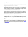
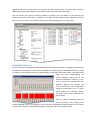
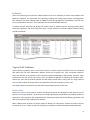
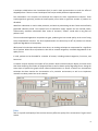
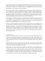
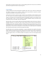
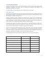
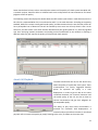
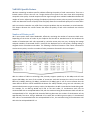
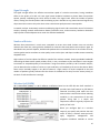
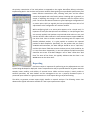
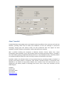
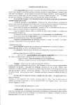
Monitoring and Troubleshooting VoIP Networks with a Network Analyzer Executive Summary Voice over IP (VoIP) is rapidly changing the way we use the telephone for voice communications. The term "Voice over IP" defines the transport of VoIP‐based networks, including the signaling and streaming protocols as well as describing the codecs. VoIP is widely used by all kinds of consumers ranging from computer enthusiasts who are excited to get free long‐distance calls over the Internet to full‐scale enterprise solutions targeted to replace the entire infrastructure inherent to analog telephony. There is no doubt that VoIP technology has everything in it to reduce communication costs significantly when compared to traditional analog telephony. Achieving call quality comparable with the quality of calls carried over PSTN networks is another matter. Deploying Voice over IP solutions requires careful analysis of network requirements and current conditions in order to provide call quality comparable to analog (PSTN) carriers. This White Paper describes the potential quality issues that must be addressed when developing or deploying a VoIP solution over both wireless (Wi‐Fi) and wired (Ethernet) network infrastructures. Copyright © 2008 TamoSoft All Rights Reserved. No part of this work can be reproduced or duplicated in any form without the expressed written permission of TamoSoft. Protocol Overview...............................................................................................................................................3 Signaling ..........................................................................................................................................................3 Streams............................................................................................................................................................4 Codecs .............................................................................................................................................................5 Monitoring VoIP Networks..................................................................................................................................6 Status of Current Calls.....................................................................................................................................6 Details about Current Calls..............................................................................................................................6 Bandwidth Utilization......................................................................................................................................7 Endpoints ........................................................................................................................................................8 Typical VoIP Problems .........................................................................................................................................8 Packet Loss ......................................................................................................................................................8 Jitter ................................................................................................................................................................9 Sequence Errors ............................................................................................................................................10 Codec Quality ................................................................................................................................................11 Assessing Sound Quality....................................................................................................................................12 MOS and R‐Factor .........................................................................................................................................12 Actual Call Playback.......................................................................................................................................13 VoWLAN‐Specific Factors ..................................................................................................................................14 Number of Clients per AP..............................................................................................................................14 Signal Strength ..............................................................................................................................................15 Number of Retries .........................................................................................................................................15 Wireless QoS (WMM)....................................................................................................................................15 Reporting...........................................................................................................................................................16 About TamoSoft ................................................................................................................................................17 2 Protocol Overview This chapter overviews the VoIP transport protocol. Voice over IP uses the Internet Protocol (IP) as an underlying transport base. Voice is digitized, converted to IP packets, and transmitted from point to point over an IP network. Signaling VoIP standards define numerous signaling protocols that are used to set up and carry out the calls, transmit information required to identify and locate remote callers, and negotiate carrier and endpoint capabilities. Different companies developed numerous different signaling protocols within the VoIP scope. SIP and H.323 are dominating the VoIP arena as the most commonly used signaling protocols. Choosing one signaling protocol over another when developing a VoIP solution is a matter of a set service requirement and the choice of equipment. SIP is commonly chosen among the full‐scale VoIP carriers to make use of the abundance of SIP‐compatible VoIP devices including the numerous inexpensive SIP phones and adapters. When multimedia communication over IP networks is required, including video conferencing and data calls in addition to audio transmission, H.323 becomes the natural choice. As defined by the scope of the signaling protocols, there are numerous potential problems that may arise because of compatibility or networking problems. The dreadful "unable to connect" problem lies frequently in the domain of signaling protocols. The two peers, once located, may be unable to connect because of compatibility problems between the two endpoints (various SIP implementations are especially prone to this problem) as well as the lack of the required features such as conference calling in one of the connecting devices. A network analyzer should recognize and support both SIP and H.323 signaling protocols, allowing the detection of problems that occur on the signaling phase early during the implementation of a VoIP system. Throughout this white paper, we'll be illustrating the problems and solutions with the help of CommView and CommView for WiFi, software‐based network analyzers for wired and wireless networks that include a VoIP analysis engine. 3 Streams Once the peers are located and a connection is made, the streaming of voice packets begins to occur. In order for the voice conversations to sound natural, without echoes and delays, the voice packets must be transferred over the IP network in real‐time. All VoIP standards use Real‐time Transport Protocol (RTP) for streaming voice packets in real‐time. RTP standard does not define, and therefore does not require the use of any specific UDP port, leaving it up to endpoints to agree on a certain port to commence a voice call. The floating‐port implementation makes it difficult to traverse firewalls, often requiring the use of dedicated STUN servers to synchronize the endpoints. A frequent VoIP connectivity problem occurs while attempting to send or receive voice packets via a more or less random port that is blocked by a firewall. A network analyzer allows the RTP streams associated with a specific signaling session to be clearly seen, as well as the IP addresses and the ports being used for the VoIP call, which helps faster and easier deployment of a VoIP system. 4 RTP does not use TCP protocol for transmitting voice packets. Despite the fact that TCP guarantees the delivery of the packets, its session initiation time and associated delays are unacceptable for transferring multimedia data in real‐time. Therefore, UDP is the natural choice here. As there is no recovery for the packets not delivered to the recipient, a certain percentage of voice packets are typically lost. While VoIP does provide means to reconstruct the lost packets without significant loss of voice call quality, packet loss beyond a certain level starts to noticeably degrade the quality of the conversation. The illustration above displays the numbers of lost packets, allowing identifying network problems on the streaming phase. RTP encapsulates additional information in every voice packet, including payload type identification to identify the type of content being transmitted, sequence numbering that is used to detect and identify the lost packets, and time stamping to allow synchronization and jitter calculations. The additional information is extremely handy when analyzing RTP streams in order to identify the source of quality issues. Codecs In order to convert an analog voice signal into a set of digital packets and then reconstruct the packets back into audible voice, special voice codecs were developed. Codecs are used to encode voice into digital form, and decode it back into audible analog form when received. In VoIP, codecs are used to encode voice for streaming across the IP network. There are numerous codecs on the market, many being publicly available at no charge. Codecs vary in the sound quality they deliver, using different bandwidth and computational requirements. With few exceptions, codecs employ compression to save network bandwidth at the expense of using more CPU and memory resources and/or delivering lower voice quality on the receiving end. The 5 less bandwidth and computational power a codec requires for achieving identical sound quality, the better it is considered to serve its purpose. G.711 is a common open‐source and royalty‐free, high bitrate codec. This codec does not require licensing fees and uses very little computational resources while providing the best possible sound quality at the expense of higher than usual network bandwidth. On the other hand, G.723 and G.729 (patent‐protected in some countries) consume 3 to 4 times less bandwidth than G.711 at the expense of increased CPU and memory load and slightly lower sound quality. There are numerous other free and licensed codecs on the market, each offering a different tradeoff between computational requirements, bandwidth, and voice quality. Each VoIP service or endpoint supports several different codecs. In order to successfully communicate, the two endpoints must negotiate a common codec they will both use. While issues resulting from codec incompatibility or the lack of common codecs among heterogeneous infrastructures are rare, these problems are also hard to detect. One can identify SIP session errors by looking at codec mismatches, as illustrated by the CommView screen shot. Monitoring VoIP Networks This chapter overviews major network parameters that shall be monitored by a network traffic analyzer in wired and WiFi VoIP networks (WiFi VoIP networks are often referred to as "VoWLAN" or "VoFi"). While the cost and technological benefits of VoIP infrastructure are a notch above the POTN networks, the end users of the technology are used to high quality and reliability of conversations. If significant sacrifices have to be made regarding the call quality, many users will not be willing to switch to the new technology. In many cases, especially where local area network (LAN) infrastructures are involved, it is totally possible and relatively easy for a network administrator to control the quality of voice transmission by controlling network parameters such as bandwidth utilization, packet loss and delays. Therefore, in addition to the many factors that are specific to VoIP applications, a network traffic analyzer shall be able to monitor network conditions and bandwidth utilization. Status of Current Calls A network analyzer shall be able to display the status of all VoIP calls, providing additional call details by request. The following screen shots illustrate the typical call details available to a network analyzer. Details about Current Calls Being able to see the details about current calls allows identifying and resolving connectivity problems on the networking and protocol levels. Call details include source and destination IP addresses, time of the 6 beginning and end of a conversation, call duration, call status, quality score, user agent types, as well as additional, protocol‐specific details such as authentication information and codec types. One can identify many types of network problems by looking at the call details, as illustrated by the following CommView screen shot. In addition to the high‐level and statistical data displayed on the left pane, the user has access to the low‐level actual log of the signaling session on the right pane. Bandwidth Utilization The need for monitoring network bandwidth and controlling network conditions is paramount for delivering the expected voice quality in a VoIP system. VoIP adds strict requirements for bandwidth utilization, making it necessary to continuously monitor the network under normal and critical loads at least at the deployment stage and while troubleshooting call quality problems. Being able to see network bandwidth utilization in real‐ time is essential for understanding the difference between the optimum and current environment, often enlightening network administrators that a simple traffic shaping can essentially increase the quality of the calls transferred over that network. One can identify bandwidth utilization issues by looking at the shape of the Stream Bandwidth chart, as illustrated on the screen shot. A bandwidth utilization problem can be clearly seen with the odd shape of the bandwidth graph, sharp spikes and uneven packet intervals. 7 Endpoints There are multiple types of end‐user endpoint devices such as PC software, IP phones, VoIP adaptors and gateways. Endpoints are responsible for originating, handling and ending conversations. Heterogeneous VoIP networks may have multiple types of endpoints with varying degrees of compatibility with the VoIP server and between each other. This is especially true for SIP‐based VoIP networks. A network analyzer identifies and displays the model names of endpoint devices, allowing tracking down connectivity problems and often fixing them with a simple software or firmware update without hunting around the network. Typical VoIP Problems Due to human perception, VoIP is much more sensitive to certain network conditions that are considered well within spec for most applications. Network issues such as packet loss, jitter, and packet sequence errors are inherent to IP networks, and are well corrected and tolerated by data transfer protocols. Voice transmissions are real‐time by the nature; hence the different approach to handling the network issues. Packet loss, jitter and out‐of‐order packets are tied closely to each other. Taking care of a single network issue can often reduce all three problems and significantly improve the quality of voice calls. This chapter discusses network issues that affect the perceptual quality of VoIP calls. Packet Loss Packet loss occurs in every kind of network. All network protocols are designed to cope with the loss of packets in one way or another. TCP protocol, for example, guarantees packet delivery by sending re‐delivery requests for the lost packets. RTP employed by the VoIP protocol does not provide delivery guarantee, and VoIP must implement the handling of lost packets. While a data transfer protocol can simply request re‐delivery of a lost packet, VoIP has no time to wait for the packet to arrive. In order to maintain call quality, lost packets are substituted with interpolated data. 8 A technique called Packet Loss Concealment (PLC) is used in VoIP communications to mask the effect of dropped packets. There are several techniques that may be used by different implementations. Zero substitution is the simplest PLC technique that requires the least computational resources. These simple algorithms generally provide the lowest‐quality sound when a significant number of packets are discarded. Waveform substitution is used in older protocols, and works by substituting the lost frames with artificially generated substitute sound. The simplest form of substitution simply repeats the last received packet. Unfortunately, waveform substitution often results in unnatural, "robotic" sound when a long burst of packets is lost. The more advanced algorithms interpolate the gaps, producing the best sound quality at the cost of using extra computational resources. The best implementation can tolerate up to 20% of packets lost without significant degradation of voice quality. While some PLC techniques work better than others, no masking technique can compensate for a significant loss of packets. When bursts of packets are lost due to network congestion, noticeable degradation of call quality occurs. In VoIP, packets can be discarded for a number of reasons, including network congestion, line errors, and late arrival. A network analyzer displays the number of lost packets. Better network analyzers display real‐time charts that allow visualizing the number of dropped packets as well as detect quality‐degrading bursts. Seeing the exact shape of packet‐loss graphs allows network administrators to choose a Packet Loss Concealment technique that best matches the characteristics of a particular environment, as well as to implement measures to reduce packet loss on the network. Jitter Jitter is a specific VoIP Quality of Service issue that may affect the quality of the conversation if it goes out of control. 9 Unlike network delay, jitter does not occur because of the packet delay, but because of a variation of packet delays. As VoIP endpoints try to compensate for jitter by increasing the size of the packet buffer, jitter causes delays in the conversation. If the variation becomes too high and exceeds 150ms, callers notice the delay and often revert to a walkie‐talkie style of conversation. There are several steps to be taken to reduce jitter both on the network level and in the VoIP endpoints such as VoIP software, IP phones or dedicated VoIP adaptors. By definition, reducing the delays on the network helps keep the buffer under 150ms even if a significant variation is present. While the reduced delay does not necessarily remove the variation, it still effectively reduces the degree to which the effect is pronounced and brings it to the point where it's unnoticeable by the callers. Prioritizing VoIP traffic and implementing bandwidth shaping also helps reduce the variation of packet delay. At the endpoint, it is essential to optimize jitter buffering. While greater buffers reduce and remove the jitter, anything over 150ms noticeably affects the perceived quality of the conversation. Adaptive algorithms to control buffer size depending on the current network conditions are often quite effective. Fiddling with packet size or using a different codec (e.g. G.711) often helps control jitter. While jitter is caused by network delays more often than by endpoints, certain resource‐struggling systems that are executed in concurrent environments, such as VoIP soft‐phones, may introduce significant and unpredictable variations in packet delays. While developing VoIP endpoints or examining call quality problems within existing VoIP infrastructure, it is very important to isolate the cause of jitter. A network analyzing tool can be extremely handy in localizing the source of the problem quickly and efficiently. A good network analyzer is capable of calculating jitter for every RTP stream and building jitter and jitter deviation charts along the time axis. Sequence Errors Data packets travel independently of one another, and are subject to various delays depending on the exact route they take. Out‐of‐sequence packets are not considered a problem for data transfers, as data transfer protocols can re‐order packets and reconstruct data without corruption. Due to the time‐sensitive nature of voice communications, VoIP systems are required to handle out‐of‐sequence packets in quite a different manner. Some VoIP systems discard packets received out of order, while other systems discard out‐of‐order packets if they exceed the size of the internal buffer, which in turn causes jitter as described in the previous chapter. Sequence errors cause significant degradation of call quality. Sequence errors may occur because of the way packets are routed. Packets may travel different paths through different IP networks, causing different delivery times. As a result, lower‐numbered packets may arrive at the endpoint later than higher‐numbered ones. The packets are usually received in the buffer, allowing the endpoint to rearrange out‐of‐order frames and reconstruct the original signal. However, the size of internal buffer is limited to control jitter, and significant variance in the orderly delivery of packets may cause the endpoints to discard frames, resulting in both jitter and dropped packet issues. 10 Routing VoIP calls through consistent routes to avoid spreading packets from the same call over different paths allows for significant reduction in sequencing errors. Codec Quality A codec is software that converts audio signals into digital frames and vice versa. Codecs are characterized with different sampling rates and resolutions. Different codecs employ different compression methods, using different bandwidth and computational requirements. Choosing the best codec for particular network conditions may considerably increase the quality of voice calls. If the network has low effective bandwidth, choosing otherwise great lossless G.711 codec would be a mistake, as the quality of the calls would suffer because of bandwidth limitations and lost packets rather than codec quality. If there is less than 64 Kbit/s of available bandwidth, picking a low‐bitrate, high‐ compression G.729 or G.723 codec is much more appropriate. Note that while a local area network (LAN) may provide high bandwidth, external calls may be subject to bandwidth bottleneck in the upstream. ADSL and cable network providers often offer limited upstream bandwidth, which results in upstream congestion if multiple VoIP calls are carried concurrently. In this case, low‐bandwidth codecs may provide better results. G.711 (PCM), a high‐bandwidth codec, provides the best audio quality yet consumes the most bandwidth. G.729a (CS‐ACELP), G.723.1 (MP‐MLQ) and G.726 (ADPCM) offer varying conversation quality, sorted by decreasing relative quality. The codec choice will not take place automatically. A system administrator must specify and prioritize codecs available to the particular VoIP system. Taking care of the wrong choice of codec may significantly improve conversation quality. By logging and displaying the session flow, a network analyzer allows seeing the codec negation process, i.e. the codecs available to the endpoints, as well as the final negotiated codec choice. 11 Assessing Sound Quality Measuring sound quality by placing a test call and listening to the remote party is highly subjective when developing or deploying a VoIP system. There are existing formal methods to give qualitative and quantitative assessments to voice quality. This chapter explains the methods used to assess the quality of a VoIP conversation. MOS and RFactor In order to provide quantitative assessment of the quality of VoIP communications, the Mean Opinion Score (MOS) has been introduced. The MOS indicates the perceived voice quality of a VoIP conversation, ranking the call quality as a number in the range 1 to 5. Originally, the MOS was meant to represent the arithmetic mean average of all the individual quality assessments given by people who listened to a test phone call and ranked the quality of that call. Today, human participation is no longer required to determine the quality of the audio stream. Modern VoIP quality assessment tools employ artificial software models to calculate the MOS. The MOS is highly subjective. One should not make decisions on a VoIP system based on the MOS alone. Other measurable parameters should be analyzed such as network delay, packet loss, jitter, and so on. As an alternative to the MOS, a different, less subjective rating has been introduced. R‐Factor is an alternative method of assessing call quality. Scaling from 0 to 120 as opposed to the limited scale of 1 to 5 makes R‐Factor a somewhat more precise tool for measuring voice quality. R‐Factor is calculated by evaluating user perceptions as well as the objective factors that affect the overall quality of a VoIP system, accounting for the Network R‐factor and the User R‐factor separately. The following table demonstrates the effect of the MOS and R‐Factor on the perceived call quality. User Satisfaction Level MOS R‐Factor Maximum using G.711 4.4 93 Very satisfied 4.3‐5.0 90‐100 Satisfied 4.0‐4.3 80‐90 Some users satisfied 3.6‐4.0 70‐80 Many users dissatisfied 3.1‐3.6 60‐70 Nearly all users dissatisfied 2.6‐3.1 50‐60 Not recommended 1.0‐2.6 Less than 50 12 Some users believe R‐Factor to be a more objective measure of the quality of a VoIP system than MOS. Still, a network analyzer should be able to calculate both scores and produce the two assessments for better judgment of the call quality. The following screen shot displays the details about two RTP streams (one stream in each direction) within a SIP call with a measured MOS of 4.0 in one direction and 2.7 in the other direction. According to the quality standard, MOS of 4.0 means overall good sound quality, and demonstrates that the one direction of the call has a perceptible level of distortion that will be noticed by some users but will only disturb a few. At the same time, the RTP stream in the other direction demonstrates poor quality (MOS of 2.7), with varying MOS over time. Analyzing network parameters and making certain modifications to the network or choosing a different codec may still improve the quality of this particular VoIP network. Actual Call Playback The MOS and R‐Factor do not tell the whole story about the quality of a particular VoIP system. These measurements are merely suggested baseline points for expected call quality in a VoIP deployment. In order to get an idea on the exact correlation between the numerical measures and the actual quality of the call, one has to listen to various conversations and give their judgment on the acceptable quality. The ability to play back actual conversations is essential for successful VoIP deployments. A network analyzer provides the means to record and play back calls to assess voice quality by simply listening to the voice, as shown on the screen shot. 13 VoWLANSpecific Factors Wireless networking introduces specific problems affecting the quality of VoIP conversations. There are a limited number of users who can use a single wireless access point at the same time while maintaining acceptable voice quality. Limited reception and low signal strength alter available bandwidth and affect the number of retries. Adjusting the settings of endpoints and wireless access points to permit prioritizing voice traffic over data with the use of Quality of Service (QoS) allows for increased call quality with no extra effort. VoIP over wireless networks may suffer from numerous problems that are nonexistent on wired networks. This chapter discusses the various factors that affect the quality of VoIP calls transferred over wireless networks. Number of Clients per AP Wi‐Fi access points have limited bandwidth, effectively restricting the number of concurrent VoIP users. Depending on the choice of codecs by the endpoints and the 802.11 standard used in the hardware the number of simultaneous VoIP calls supported by a wireless access point may vary. Analyzing the average and peak numbers of connected clients is crucial for the deployment of a VoIP system, allowing making a weighed choice of hardware and codecs. The following screenshot illustrates a few clients connected to wireless access points, as well as a number of other parameters discussed in the next chapters. With the advent of 802.11n technology that presently supports speeds up to 300 Mbps and will soon support 600 Mbps, the issue of the number of concurrent VoIP calls becomes less critical, but the older 802.11b (11 Mbps), 802.11g (54 Mbps), and 802.11a (54 Mbps) gear is still far more common than the newer 802.11n devices. Online bandwidth calculators are widely available; using one such calculator, the network administrator can get necessary metrics that depend on the 802.11 standard and codes being used. For example, for an 802.11g WLAN and G.729 as the VoIP codec, 27 simultaneous VoIP calls are recommended with an anticipated MOS of 3.8, with the maximum being 98 simultaneous VoIP calls with an anticipated MOS of 3.2. Using 802.11b instead of 802.11g decreases the number of simultaneous calls by approximately five times. Using a wideband G.711 codec with an 802.11g access point, 15 simultaneous VoIP calls are recommended with the anticipated MOS of 4.1, the maximum being 53 simultaneous VoIP calls with the anticipated MOS of 3.4. 14 Signal Strength The signal strength affects the effective transmission speed of a wireless connection, having immediate effect on the quality of a VoIP call. Low signal causes endpoint hardware to choose lower transmission speeds, possibly invalidating the initial choice of codec. Low signal levels affect the number of packet retries, causing out‐of‐order packets and contributing to jitter. Needless to say, lower than usual signals may drop transmission rates to the point where voice transmission quality becomes unacceptable. A network analyzer continuously monitors and displays signal levels and transmission rates of all wireless stations, allowing network administrators detect insufficient rates, make necessary hardware relocations and/or perform codec adjustments to match the effective bandwidth. Number of Retries Wireless data transmission is much more susceptible to errors than wired. Packets sent over wireless networks are often lost, causing wireless hardware to retransmit the same packets over and over again. As described in the previous chapters, VoIP discards packets that are received too late or out of order. As such, wireless packet retries contribute to voice quality issues such as jitter and drops in audio streams caused by dropped frames. High numbers of retries reduce the effective speed of the wireless network, lowering available bandwidth and making the data transfer speed variable; which, in turn, contributes to jitter and makes it even tougher to maintain an acceptable quality of conversation. Using the statistics proved by a Wi‐Fi network analyzer, you can determine the number of retries on a per‐node basis, as illustrated by the screen shot above. While some retries inevitably happen in any 802.11 network, a high number of retries compared to the total number of packets typically indicates that the clients are located too far away from the access point(s) or the level of radio interference is too high. Wireless QoS (WMM) Wi‐Fi Multimedia (WMM) is a Wi‐Fi Alliance certification based on the IEEE 802.11e draft standard. It provides basic QoS features to IEEE 802.11 networks. Prioritizing VoIP traffic over less time‐sensitive transmissions allows reducing variability in the transmission of the VoIP packets. Using QoS is a simple and inexpensive solution to greatly improve the quality of VoIP calls. When you configure QoS on a wireless network, you specify and prioritize the VoIP traffic. In effect, a wireless access point will apply congestion management and congestion avoidance methods to ensure 15 the priority transmission of the VoIP packets as opposed to the regular best‐effort delivery technique. Implementing QoS in the wireless environment network allows getting more predictable performance and better effective transmission rates, reducing VoIP jitter and the effects caused by dropped and out‐of‐order packets. Enabling QoS is generally as simple as adjusting the settings in the endpoints and the wireless access point. The screen shot above illustrates a typical QoS engine configuration of an access point. QoS has arguably the best price/performance ratio of all adjustments to the configuration of a wireless network. While configuring QoS in an access point appears to be a simple task, it's important to verify that the QoS works as intended, i.e. the QoS engine rules are correctly applied, VoIP packets are prioritized while others are not, and that the wireless nodes involved in VoIP communications support WMM on the driver level. Since a wireless network monitoring tool can capture and decode individual packets, it is quite possible to examine the captured packets for QoS compliance. Specifically, for the packets that are used in VoWLAN communications, the Data Subtype should be set to "QoS Data," and the QoS Control field that contains the data priority level should be set to a non‐zero value. Respectively, in non‐VoIP packets the QoS Control field should be set to zero. If the Data Subtype is set to "Data" rather than "QoS Data" for some of the clients, this typically indicates that the client is not WMM‐aware on the driver level. Reporting Real‐time analysis is important for performing on‐site adjustments to a VoIP system being developed or deployed. A more comprehensive analysis provides benefits of greater statistics samples, better usability, and visibility of essential issues. While real‐time analysis is mostly usable to technical specialists, the team leaders and the management can use a properly formatted report. A processed report makes for a great presentation or a brief report during a corporate meeting. The ability to generate custom reports highly benefits a network analyzer. The following screen shot demonstrates typical information available in a VoIP system performance report. 16 About TamoSoft TamoSoft develops cutting‐edge security and network monitoring software for the Internet and Local Area Networks, providing clients with the ability and confidence to meet the challenges of tomorrow's technology. Keeping pace with industry trends, we offer professional tools that support the latest standards, protocols, software and hardware in both wired and wireless networks. With a portfolio including such companies as Motorola, Siemens, Ericsson, Nokia, Cisco, Lucent Technologies, Nortel Networks, Unisys, UBS, Dresdner Bank AG, Olympus and General Electric, TamoSoft is one of the fastest growing IT application development firms in the marketplace today. TamoSoft products are available through this Web site as well as through a network of distributors and resellers. Founded in 1998 as the software division of a Cyprus‐based business consulting company, TamoSoft is a privately held company based in Christchurch, New Zealand. TamoSoft employs an international team dedicated to the creation of high quality software that customers from over 100 countries rely on and partners with industry leaders in technology and services, such as Zone Labs, Visualware, and The CWNP Program. TamoSoft PO Box 1385 Christchurch 8140 New Zealand www.tamos.com 17