1
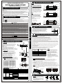
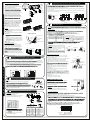
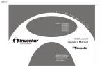
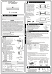
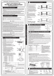
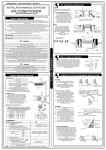
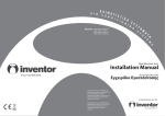
A2MVI-09 / A2MVO-09
A2MVI-12 / A2MVO-12
A2MVI-18 / A2MVO-18
A2MVI-24 / A2MVO-24
P2MVI-09 / P2MVO-09
P2MVI-12 / P2MVO-12
P2MVI-18 / P2MVO-18
P2MVI-24 / P2MVO-24
Wall Mounted Unit
Installation Manual
Επιτοίχια Μονάδα
Εγχειρίδιο Εγκατάστασης
Σας ευχαριστούμε που επιλέξατε τη
μονάδα κλιματισμού της INVENTOR. Για
τη σωστή χρήση της μονάδας.
παρακαλούμε διαβάστε προσεκτικά το
παρόν εγχειρίδιο και φυλάξτε το για
αναφορά στο μέλλον.
Thank you for choosing INVENTOR air
conditioning system. For correct use of
this unit, please read this manual
carefully and keep it for future
reference.
English/Ελληνικά/ Română
CS236I-BP12FU(L) 20131022
1
INSTALLATION MANUAL FOR
INSTALLATION PLATE MOUNTING
NOTE:
INSTALLATION PRECAUTIONS
Please read this installation manual carefully before operating the unit to ensure correct installation.
If the power cord is damaged, replacement work shall be performed by authorised personnel only.
Installation work must be performed in accordance with the national wiring standards by authorised
personnel only.
Contact an authorized service technician for repair, maintenance and installation of this unit.
This appliance is not intended for use by persons(including children) with reduced physical, sensory
or mental capabilities, or lack of experience and knowledge, unless they have been given supervision
or instruction concerning use of the appliance by persons responsible for their safety.
Children should be supervised to ensure that they do not play with the appliance.
All the pictures in the instructions are for explanation purposes only. The actual shape should prevail.
The design and specifications are subject to change without prior notice for product improvement.
Consult with the sales agency or manufacturer for details.
NOTE:
Mount the Installation Plate and drill
holes in the wall according to the
wall structure and corresponding
mounting points on the installation
plate. The installation plate provided
with the machine differ from appliance
to appliance.
(Dimensions are in " mm " unless
otherwise stated)
SAFETY PRECAUTIONS
Please read these safety precautions carefully before installation
Be sure to follow all the precautions below, they are all important for ensuring safety.
This symbol indicates the possibility of death or serious injury.
CAUTION
This symbol indicates the possibility of injury or damage to property.
Correct orientation
of Installation Plate
120mm or
more to wall
120mm or
more to wall
Left rear side
refrigerant
pipe hole 65
A
Right rear side
refrigerant pipe
hole 65
9000Btu/h models(A:715, B:250, C:85, D:88)
150mm or more to ceiling
C
D
Indoor unit outline
120mm or
more to wall
120mm or
more to wall
Left rear side
refrigerant
pipe hole 65
A
Right rear side
refrigerant pipe
hole 65
12000Btu/h models(A:800, B:275, C:100, D:95)
150mm or more to ceiling
C
D
Indoor unit outline
120mm or
more to wall
120mm or
more to wall
B
WARNING
Indoor unit outline
B
Installation Plate Mounting
1. Fit the installation plate horizontally
on structural parts of the wall with
spaces around the installation plate.
2. If the wall is made of brick, concrete
or the like, drill five or eight 5mm
diameter holes in the wall.Insert Clip
anchor for appropriate mounting screws.
3. Fit the installation plate on the wall
with five or eight type " A " screws.
D
B
(Split Wall-Mounted Type)
150mm or more to ceiling
C
45
ROOM AIR CONDITIONER
The mounting wall is strong and solid
enough to prevent it from the vibration.
45
202000192582
CAUTION
1) This equipment must be grounded and installed with ground leakage current breaker. It may cause
electrical shock if grounding is not perfect.
2) Do not install the unit at place where leakage of flammable gas may occur. In case gas leaks and
accumulates at surrounding of the unit, it may cause fire.
3) Carry out drainage piping as mentioned in installation instructions. If drainage is not perfect, water
may enter the room and damage the furniture.
Indoor unit
15cm or more
ore
12cm or m
2.3m or more
mo
200c
60cm or more
30c
30cm
rm
ore
m or
or m
ore
more
60c
Settlement of outdoor unit
mo
276
276
780x540x250
549
760x590x285
530
290
845x700x320
560
335
810x558x310
549
325
670x540x265
481
276
ACCESSORIES
Number Name of Accessories
3
4
5
6
Gas side
7
8
9
10
3
12.7
16
Remote controller
optional
Self-tapping Screw B ST2.9x10
parts
Remote controller holder
Air freshening filter(used to install on Air filter)
Outdoor
5-7mm
Indoor
CONNECT THE CABLE TO THE INDOOR UNIT
Electrical work
Electric safety regulations for the initial Installation
1. If there is serious safety problem about the power supply, the technicians should refuse to install
the air conditioner and explain to the client until the problem is solved.
2. Power voltage should be in the range of 90%~110%of rated voltage.
3. The surge protector and main power switch with a 1.5 times capacity of Max. Current of the unit should
be installed in power circuit. Ensure the air conditioner is grounded well.
4. The appliance shall be installed in accordance with national wiring regulations. Do not operate your air
conditioner in a wet room such as a bathroom or laundry room.
5. An all-pole disconnection device which has at least 3mm clearances in all poles, and have a leakage
current that may exceed 10mA, the residual current device(RCD) having a rated residual operating
current not exceeding 30mA, and disconnection must be incorporated in the fixed wiring in accordance
with the wiring rules.
6. For the unit adopts auxiliary electric heater, keep at least 1 meter away from the nearest combustible
materials.
7. According to the attached Electrical Connection Diagram located on the panel of the indoor & outdoor
unit to connect the wire.
8. All wiring must comply with local and national electrical codes and be installed by qualified and
skilled electricians.
9. An individual branch circuit and single receptacle used only for this air conditioner must be
available. See the following table for suggested wire sizes and fuse specifications:
Rated curr ent Nominal cross-sectional
of appliance
area
(A)
(mm2)
>3 and 6
0.75
>6 and 10
1
>10 and 16
1.5
2.5
>16 and 25
4
>25 and 32
6
>32 and 40
NOTE:
The wire size of power supply cord and
interconnected wire and the current of
the fuse or switch are determined by the
maximum current indicated on the
nameplate which located on the side
panel of the unit. Please refer to the
nameplate before selecting the wire size,
fuse or switch.
The controller of the air conditioner
designed with a fuse protection function
under abnormal conditions, the
specifications of the fuse have printed on
the circuit board, such as: T3.15A/250VAC,
T5A/250VAC, etc.
NOTE: Before performing any electrical work, turn off the main power to the system.
1. The inside and outside connecting cable can be connected without removing the front grille.
2. The indoor power cord type is H05VV-F or H05V2V2-F, the outdoor power cord and
interconnected cord type is H07RN-F.
3. Lift the indoor unit panel up, remove the electrical box cover by loosening the screw.
4. Ensure the colour of wires of outdoor unit and the terminal Nos. are the same to the indoor s
respectively.
5. Wrap those cables not connected with terminals with insulation tapes, so that they will not touch
any electrical components. Secure the cable onto the control board with the cord clamp.
NOTE: If used as MONO unit, for the standby control needs, the cross section area of cable connected
to L(1)/W, 1/1(L), 2(N) must be sufficient for the maximum system current. The maximum system current is
equal to the sum of indoor unit and outdoor unit rated current. If used as MULTI unit, L(1)/W on the
terminal block does not need to be connected.
Air inlet
Air outlet
Electronic box
cover
1
5-8(depending on models)
5-8(depending on models)
1
1
Parts you must purchase. The pipe
size differ from appliance to appliance.
Consult the technician for the proper
size.
1
2
1
1
NOTE: Except the above parts provided,the other parts needed during installation you must
purchase.
Terminal block of indoor unit
Front Panel
Qty
Installation Plate
Clip Anchor
Self-tapping Screw A ST3.9x25
Seal(For cooling & heating models only)
Drain Joint(For cooling & heating models only
6.35
Connecting Liquid side
9.52
pipe
9.52
Assembly
Wall
1. Determine hole positions according to left and right
side of the installation plate. The hole center is obtained
by measuring the distance as shown in the diagram above.
2. Dirll the piping plate hole with 65mm hole-core drill.
3. Drill the piping hole at either the right or the left and the
hole should be slightly slanted to the outdoor side.
4. Always take steps to protect the pipe when drilling metal
grid,metal plate or the like.
,
A
Air inlet
B
250
460
D
458
685x430x260
1
2
W
B(mm)
700x540x240
I
N
D
O
O
R
DRILL A HOLE IN THE WALL
Connect the cable to the indoor unit
Mounting dimensions
A(mm)
2
rm
ore
Anchor the outdoor unit with a bolt and nut 10 or
8 tightly and horizontally on a concrete or rigid mount.
NOTE: The outdoor unit you purchase may be like one
of the following. Install the outdoor unit according to the
dimension as indicated in the table below:
Outdoor unit dimension
mm(WxHxD)
Right rear side
refrigerant pipe
hole 65
Minimum cross-sectional area of conductors:
Outdoor unit
If an awning is built over the unit to prevent
direct sunsight or rain,be careful that heat
radiation from the condenser is not obstructed.
There should not be any animal or plant which
could be affected by hot air discharged.
Keep the spaces indicated by arrow from wall
ceiling, fence or other obstacles.
Do not place any obstacles which may cause
a short circuit of the discharged air.
A
18000Btu/h models(A:940, B:275, C:110, D:100)
U
N
I
T
SELECT THE BEST LOCATION
There should not be any heat source or stream
near the unit.
There should not be any obstacles blocking the
air circulation.
12cm
or mo
A place where air circulation in the room is good.
re
A place where drainage can be easily done.
A place where noise prevention is taken into
consideration.
Do not install the unit near the door way.
Ensure the spaces indicated by arrows from the
wall,ceiling,fence or other obstacles.
There should not be any direct sunlight. If unavoidable,
sunlight prevention should be taken into consideration.
Left rear side
refrigerant
pipe hole 65
45
WARNING
1) Install according to this installation instructions strictly. If installation is defective, it will cause water
leakage, electrical shock,or fire.
2) Use the included accessories parts and specified parts for installation. otherwise, it will cause the set
to fall, water leakage, electrical shock,or fire.
3) Install at a strong and firm location which is able to withstand the set s weight. If the strength is not
enough or installation is not properly done, the set will drop and cause injury.
4) For electrical work, follow the local national wiring standard, regulation and this installation instructions.
An independent circuit and single outlet must be used. If electrical circuit capacity is not enough or
defect found in electrical work, it will cause electrical shock,or fire.
5) Use the specified cable and connect tightly and clamp the cable so that no external force will be acted
on the terminal. If connection or fixing is not perfect, it will cause heat-up or fire at the connection.
6) Wiring routing must be properly arranged so that control board cover is fixed properly. If control board
cover is not fixed perfectly, it will overheat at connection point of terminal, fire or electrical shock.
7) When carrying out piping connection, take care not to let air substances other than the specified
refrigerant go into refrigeration cycle. Otherwise, it will cause lower capacity,abnormal high pressure
in the refrigeration cycle, explosion and injury.
8) Do not modify the length of the power supply cord or use of extension cord, and do not share the
single outlet with other electrical appliances. Otherwise, it will cause fire or electrical shock.
L(1) 1 2(N)
S
To outdoor unit
Model A
4
W 1(L) 2(N)
S
To outdoor unit
Model B
CONNECTIVE PIPE AND DRAINAGE INSTALLATION
Drainage
1. Run the drain hose sloping downward.
Do not install the drain hose as illustrated
in wrong figures.
2. When connecting extension drain hose,
insulate the connecting part of extension
drain hose with a shield pipe, do not let
the drain hose slack.
Right
Wrong
4
Connective pipe installation
I
N
D
O
O
R
U
N
I
T
1. For the left-hand and right-hand piping,
remove the pipe cover from the side panel.
2. For the right back and left back piping,
install the piping as shown.
NOTE:Both sides drainage structure is
standard. For both sides drainage structure,
it can be choosen for right, left or both sides
drainage connection. If choosing both sides
drainage connection, another proper drain
hose is needed as there is only one drain
hose offered by factory. If choosing one side
drainage connection, make sure the drain
hole on the other side is well plugged.
For 9k/12k models, if choosing left-hand
or left-back piping,please choosing left side
drainage connection. The connection of the
drain hose is supposed to be done by
qualified installer in case of water leakage.
3. Bundle the tubing, connecting cable, and
drain hose with tape securely, evenly as
shown in Figure on the right.
1. Remove the electrical control board cover from the outdoor unit by loosening the screw.
2. Connect the connective cables to the terminals as identified with their respective matched numbers
on the terminal block of indoor and outdoor units.
3. Secure the cable onto the control board with the cord clamp.
4. To prevent the ingress of water, form a loop of the connective cable as illustrated in the installation
diagram of indoor and outdoor units.
5. Insulate unused cords (conductors) with PVC-tape. Process them so they do not touch any electrical
or metal parts.
Cover
5
S
1(L)
L
N
Power supply
To indoor unit Power supply
Model B
AIR PURGING AND TEST OPERATION
nominal efficiency is tested basing on the pipe length of 5 meters.
1. Air purging
The indoor unit and tubing between the indoor and outdoor unit must be leak tested and evacuated
to remove any noncondensables and moisture from the system.
Check that each tube(both liquid and gas side tubes) between the indoor and outdoor units have
been properly connected and all wiring for the test run has been completed.
Pipe length and refrigerant amount:
Connective pipe length Air purging method
Correct
Strong
wind
DRAIN JOINT INSTALLATION
different outdoor unit.
For the drain joint with the seal(Fig.A), first fit the seal onto
the drain joint, then insert the drain joint into the base pan
hole of outdoor unit, rotate 90 to securely assemble them.
To install drain joint as shown in Fig.B, insert the drain
joint into the base pan hole of outdoor unit until it remains
fixed with a clicking sound. Connecting the drain joint with
an extension drain hose (Locally purchased), in case of the
water draining off the outdoor unit during the heating mode.
Drain joint
Seal
Base pan hole
of outdoor unit
Flaring
O
(B)
Oblique Roughness Burr
Bar
A(mm)
Outer diam.
(mm)
Max.
Min.
Copper pipe
0.7
1.0
1.0
2.0
Tightening connection
Align pipes to be connected.
Sufficiently tighten the flare nut with fingers,
and then tighten it with a spanner and torque
wrench as shown.
Excessive torque can break nut depending
on installation conditions.
Liquid side: 9.52mm:
R22: (Pipe length-5)x60g/m
R410A: (Pipe length-5)x40g/m
Refrigerant
Gas side
Liquid side
B
Packed valve
Flare nut
Indoor
unit
Stopper
Cap
C
D
Flare nut
Valve body
Valve stem
Indoor unit tubing
Outer
diam.
6.35mm
9.52mm
12.7mm
16mm
1. Completely tighten the flare nuts, A, B, C, D, connect
the manifold valve charge hose to a charge port of the
Manifold valve
packed valve on the gas pipe side.
Compound meter Pressure gauge
2. Connect the charge hose connection to the vacuum
pump.
-76cmHg
3. Fully open the handle Lo of the manifold valve.
4. Operate the vacuum pump to evacuate. After starting
Handle Hi
Handle Lo
evacuation, slightly loose the flare nut of the packed
Charge
hose
valve on the gas pipe side and check that the air is
Charge hose
entering. (Operation noise of the vacuum pump changes
Vacuum pump
and a compound meter indicates 0 instead of minus)
5. After the evacuation is complete, fully close the handle
Lo of the manifold valve and stop the operation of the
vacuum pump.
Make evacuation for 15 minutes and more and check
Packed valve
that the compound meter indicates -76cmHg(-1.0x10⁵Pa).
O
6. Turn the stem of the packed valve B about 45 counterclockwise for 6~7 seconds after the gas coming out, then
tighten the flare nut again. Make sure the pressure display
in the pressure indicator is a little higher than the atmosphere
pressure.
7. Remove the charge hose from the Low pressure charge hose.
8. Fully open the packed valve stems B and A.
9. Securely tighten the cap of the packed valve.
1. Soap water method:
Apply a soap water or a liquid neutral detergent on the indoor
unit connections and outdoor unit connections by a soft brush
to check for leakage of the connecting points of the piping. If
bubbles come out, it indicates that the pipes have leakage.
2. Leak detector
Use the leak detector to check for leakage.
Indoor unit
check point
D
C
B
A
Cover
Outdoor unit
check point
A: Lo packed valve B: Hi packed valve
C and D are ends of indoor unit connection.
4. Test running
Handle
"A"
90
1. Cut a pipe with a pipe cutter.
2. Put flare nuts on pipe/tube having
completed burr removal and flare the pipe.
3. Firmly hold copper pipe in a die in the
dimension shown in the table below.
1.6
Outdoor
unit
A
CAUTION
(A)
REFRIGERANT PIPE CONNECTION
1.8
2.2
Liquid side: 6.35mm
R22: (Pipe length-5)x30g/m
R410A: (Pipe length-5)x20g/m
3. Safety and leakage check
NOTE: The drain joint is slightly different according to the
12.7
16
Use vacuum pump
2. When using the Vacuum Pump
Barrier
9.52
More than 5m
Additional amount of refrigerant to be charged
CAUTION
Incorrect
1.3
Use vacuum pump
Open the valve stem until it hits against
the stopper. Do not try to open it further.
Securely tighten the valve stem cap with
a spanner or the like.
Valve stem cap tightening torque. See
Tightening torque table.
OUTDOOR INSALLATION PRECAUTION
Strong
wind
Less than 5m
For the R410A refrigerant model, make sure the refrigerant added into air conditioner is liquid
form in any cases.
When relocating the unit to another place, using vacuum pump to perform evacuation.
Install the outdoor unit on a rigid base to prevent increasing noise level and vibration.
Determine the air outlet direction where the discharged air is not blocked.
In the case that the installation place is exposed to strong wind such as a seaside, make
sure the fan operating properly by putting the unit lengthwise along the wall or using a dust
or shield plates.
Specially in windy area, install the unit to prevent the admission of wind. If need suspending
installation, the installation bracket should accord with technique requirement in the
installation bracket diagram. The installation wall should be solid brick, concrete or the same
intensity construction, or actions to reinforce, damping supporting should be taken.
The connection between bracket and wall, bracket and the air conditioner should be firm,
stable and reliable.
Be sure there is no obstacle which block radiating air.
6.35
N
NOTE: Connective pipe length will affect the capacity and energy efficiency of the unit. The
Connect the indoor unit first, then the
outdoor unit.
Do not allow the piping to let out from the
back of the indoor unit.
Be careful not to let the drain hose slack.
Heat insulation should be done to the
extension drain hose of indoor unit.
Be sure that the drain hose is located at
the lowest side of the bundle. Locating at
the upper side can cause drain pan to
overflow inside the unit.
Never intercross nor intertwist the power
wire with any other wiring.
3
L
Model A
1. Pass the piping through the hole in the wall.
2. Hook the indoor unit onto the upper portion
of installation plate(Engage the indoor unit with
the upper edge of the installation plate). Ensure
the hooks are properly seated on the installation
plate by moving it in left and right.
3. Piping can easily be made by lifting the indoor
unit with a cushioning material between the
indoor unit and the wall. Get it out after finish
piping.
4. Press the lower left and right side of the unit
against the installation plate until hooks
engages with the their slots.
U
N
I
T
S
To indoor unit
CAUTION
2
1
Screw
Indoor unit installation
O
U
T
D
O
O
R
Terminal block of outdoor unit
Rubber plug
Because the condensed water from rear
of the indoor unit is gathered in ponding
box and is piped out of room. Do not put
anything else in the box.
1
CONNECT THE CABLE TO THE OUTDOOR UNIT
Bar
Clamp handle
Flare nut
Perform test operation after completing gas leak check at the flare nut connections and electrical
safety check.
Check that all tubing and wiring have been properly connected.
Check that the gas and liquid side service valves are fully open.
1. Connect the power, press the ON/OFF button on the remote controller to turn the unit on.
2. Use the MODE button to select COOL, HEAT, AUTO and FAN to check if all the functions works
well.
3. When the ambient temperature is too low(lower than 17OC), the unit cannot be controlled by the
remote controller to run at cooling mode, manual operation can be taken. Manual operation is
used only when the remote controller is disable or maintenance necessary.
Hold the panel sides and lift the panel up to an angle until it remains fixed with a clicking sound.
Press the Manual control button to select the AUTO or COOL, the unit will operate under Forced
AUTO or COOL mode(see User Manual for details).
4. The test operation should last about 30 minutes.
Pipings
Tightening
torque(N.cm)
Additional tightening
torque(N.cm)
1500
(153kgf.cm)
2500
(255kgf.cm)
1600
(163kgf.cm)
3500
(357kgf.cm)
4500
(459kgf.cm)
3600
(367kgf.cm)
4700
(479kgf.cm)
2600
(265kgf.cm)
Manual control
button
AUTO/COOL
20131022
1
ΕΓΧΕΙΡΙΔΙΟ ΕΓΚΑΤΑΣΤΑΣΗΣ ΓΙΑ
ΚΛΙΜΑΤΙΣΤΙΚΗ ΜΟΝΑΔΑ
ΕΓΚΑΤΑΣΤΑΣΗ ΤΗΣ ΒΑΣΗΣ
ΣΗΜΕΙΩΣΗ:
Βεβαιωθείτε ότι ο τοίχος είναι συμπαγής ώστε να
αποφευχθούν δονήσεις.
ΕΛΕΓΧΟΙ ΕΓΚΑΤΑΣΤΑΣΗΣ
Παρακαλούμε πριν την λειτουργία της μονάδας διαβάστε προεκτικά αυτό το εγχειρίδιο, για να βεβαιωθείτε ότι
έχει γίνει σωστή εγκατάσταση.
Εάν το καλώδιο τροφοδοσίας είναι φθαρμένο, θα πρέπει να αντικατασταθεί από εξειδικευμένο προσωπικό.
Η εγκατάσταση, συντήρηση και επισκευή αυτής της μονάδας θα πρέπει να γίνει από εξειδικευμένο τεχνικό.
Αυτή η μονάδα δεν πρέπει να χρησιμοποιείται από άτομα με ειδικές ανάγκες, παιδιά ή άτομα με έλλειψη
εμπειρίας και γνώσεων, εκτός αν επιβλέπονται από άτομα υπεύθυνα για την ασφάλεια τους.
Τα παιδιά θα πρέπει να επιβλέπονται, ώστε να μην παίζουν με την μονάδα.
Όλες οι εικόνες που παρουσιάζονται στο παρόν εγχειρίδιο είναι για επεξηγηματικούς λόγους μόνο. Το πραγματικό
σχήμα μπορεί να διαφέρει.
Ο σχεδιασμός και τα χαρακτηριστικά μπορεί να αλλάξουν χωρίς προειδοποίηση, για τη βελτίωση της μονάδας. Για
λεπτομέριες συμβουλευτείτε τον προμηθευτή σας.
ΣΗΜΕΙΩΣΗ:
Τοποθετήστε τη βάση και διανοίξτε οπές στον
τοίχο σύμφωνα με την δομή του τοίχου και τα
αντίστοιχα σημεία στήριξης πάνω στη βάση. Η
βάση που συνοδέυει τη μονάδα διαφέρει ανά
μοντέλο.
(Οι διαστάσεις είναι σε mm)
ΟΔΗΓΙΕΣ ΑΣΦΑΛΕΙΑΣ
Πάνω από 120mm
απόσταση από τον τοίχο
B
Πάνω από 120mm
απόσταση από τον τοίχο
Πίσω αριστερή οπή
ψυκτικών σωληνώσεων Φ65
Αυτό το σύμβολο υποδεικνύει την πιθανότητα σοβαρού τραυματισμού ή θανάτου.
ΠΡΟΣΟΧΗ
Αυτό το σύμβολο υποδεικνύει την πιθανότητα τραυματισμού ή καταστροφή περιουσίας.
Πάνω από 150mm
απόσταση από την οροφή
C
D
Περίγραμμα εσωτερικής
μονάδας
Πάνω από 120mm
απόσταση από τον τοίχο
Πάνω από 120mm
απόσταση από τον τοίχο
Πίσω αριστερή οπή
ψυκτικών σωληνώσεων Φ65
A
Πίσω δεξιά οπή
ψυκτικών
σωληνώσεων Φ65
Μοντέλα 12.000Btu/h(A:800, B:275, C:100, D:95)
Πάνω από 150mm
απόσταση από την οροφή
C
Σωστή οριοθέτηση
της βάσης στήριξης
Πίσω δεξιά οπή
ψυκτικών
σωληνώσεων Φ65
Μοντέλα 9.000Btu/h(A:715, B:250, C:85, D:88)
Παρακαλούμε διαβάστε αυτές τις οδηγίες ασφαλείας πριν την εγκατάσταση.
Ακαλουθήστε όλες τις παρακάτω οδηγίες, είναι σημαντικές για την ασφάλειά σας.
ΠΡΟΕΙΔΟΠΟΙΗΣΗ
A
B
Εγκατάσταση της Βάσης
1. Τοποθετήστε τη βάση οριζόντια στα δομικά
στοιχεία του τοίχου αφήνοντας αποστάσεις
γύρω από αυτή.
2.Εάν ο τοίχος είναι από τούβλα, τσιμέντο ή
παρόμοιο υλικό, διανοίξτε 5 ή 8 οπές των
5mm. Εισάγετε τα κατάλληλα ούπα για τις
αντίστοιχες βίδες.
3. Τοποθετήστε τη βάση στον τοίχο με 5 ή 8
βίδες τύπου "Α".
Περίγραμμα εσωτερικής
μονάδας
D
••
(Επιτοίχιες Μονάδες Διαιρούμενου Τύπου)
Πάνω από 150mm
απόσταση από την οροφή
C
••
202000192582 CS236I-BP12FU(L)
D
Περίγραμμα εσωτερικής
μονάδας
Πάνω από 120mm
απόσταση από τον τοίχο
Πάνω από 120mm
απόσταση από τον τοίχο
ΠΡΟΕΙΔΟΠΟΙΗΣΗ
2
7) Κατά τη σύνδεση των σωληνώσεων, φροντίστε να μην εισέλθει αέρας στο ψυκτικό κύκλωμα. Σε αντίθετη
περίπτωση θα προκληθεί μείωση απόδοσης, υψηλή πίεση στο ψυκτικό κύκλωμα, έκρηξη και τραυματισμός.
8) Μην κάνετε μετατροπές στο μήκος του καλωδίου και μην χρησιμοποιείτε μπαλαντέζα. Μην χρησιμοποιείτε την ίδια
πρίζα και για άλλες συσκευές. Μπορεί να προκληθεί ηλεκτροπληξία ή πυρκαγιά.
ΠΡΟΣΟΧΗ
1) Θα πρέπει να υπάρχει γείωση στη μονάδα και να τοποθετηθεί ρελέ διαφυγής. Εάν η γείωση δεν είναι σωστή μπορεί
να προκληθεί ηλεκτροπληξία.
2) Μην τοποθετείτε τη μονάδα σε μέρος όπου μπορεί να προκληθεί διαρροή εύφλεκτου αερίου. Εάν υπάρξει μεγάλη
διαρροή αερίου κοντά στη μονάδα μπορεί να προκληθεί πυρκαγιά.
3) Βεβαιωθείτε πως η σύνδεση του αγωγού αποστράγγισης έγινε σύμφωνα με τις οδηγίες εγκατάστασης. Εάν η απορροή των
συμπυκνωμάτων δεν γίνεται σωστά μπορεί να εμφανιστεί διαρροή νερού από την εσωτερική μονάδα και να φθαρούν τα έπιπλα.
ΕΠΙΛΟΓΗ ΘΕΣΗΣ
Εσωτερική Μονάδα
Πάνω από 15cm
ό 12cm
Πάνω απ
Πάνω από 2.3m
νω
Πάνω από 60cm
Πά
απ
ωα
0cm
0cm
ό 20
ω απ
Πάν
Πάν
ωα
250
460
276
276
780x540x250
549
760x590x285
530
290
845x700x320
560
335
810x558x310
549
325
670x540x265
481
276
ΕΞΑΡΤΗΜΑΤΑ
A/A
Ονομασία Εξαρτήματος
7
8
9
10
Ηλεκτρική εργασία
Κανονισμοί ασφαλείας για την αρχική εγκατάσταση
1. Εάν υπαρχει σοβαρό πρόβλημα ασφάλειας με την παροχή ρεύματος, το τεχνικό προσωπικό θα πρέπει να αρνηθεί να
προχωρήσει με την εγκατάσταση και να εξηγήσουν στον πελάτη πως δεν μπορεί να γίνει εκατάσταση αν δεν λυθεί το
πρόβλημα.
2. Η τάση δικτύου θα πρέπει να κυμαίνεται στο 90%-110% της βαθμονομημένης τάσης.
3. Στο κύκλωμα θα πρέπει να τοποθετηθεί διάταξη προστασίας υπέρτασης και ασφαλειοδιακόπτης με χωρητικότητα 1,5
φορά μεγαλύτερη από τη μέγιστη ένταση ρεύματος της μονάδας. Βεβαιωθείτε πως έχει γίνει σωστή γείωση.
4. Η μονάδα θα πρέπει να εγκατασταθεί σύμφωνα με τους εθνικού κανονισμούς. Μην λειτουργείτε τη μονάδα σε
χώρους όπως μπάνιο.
5. Οι μονάδες που έχουν εφεδρική αντίσταση πρέπει να βρίσκονται τουλάχιστον σε 1m απόσταση από εύφλεκτα υλικά.
6. Συνδέστε τα καλώδια σύμφωνα με τα ηλεκτρολογικά διαγράμματα που βρίσκονται στην εσωτερική και στην
εξωτερική μονάδα.
7. Η συνδεσμολογία της μονάδας θα πρέπει να γίνεται σύμφωνα με τους εθνικούς κανονισμούς και από εξειδικευμένο
προσωπικό.
8. Για την κλιματιστική μονάδα θα πρέπει να υπάρχει ειδικό ξεχωριστό κύκλωμα. Δείτε τον παρακάτω πίνακα για τις
διατομές των καλωδίων και τις ασφάλειες:
Γραμμή
αερίου
Ασύρματο τηλεχειριστήριο
Αυτοδιάτρητη Βίδα Β ST2.9x10
6
10
16
25
32
0.75
1
1.5
2.5
4
>32 and
40
6
6.35
9.52
9.52
12.7
16
Βάση ασύρματου τηλεχειριστηρίου
Φίλτρο καθαρισμού του αέρα (προαιρετικά για να
τοποθετηθεί στο Φίλτρο)
Η μονάδα έχει σχεδιαστεί με ειδική διάταξη
υπερέντασης. Τα χαρακτηριστικά της ασφάλειας
φαίνονται πάνω στην πλακέτα, όπως:
0cm
W
A
Είσοδος Αέρα
Είσοδος
Αέρα
Έξοδος Αέρα
ΣΗΜΕΙΩΣΗ: Πριν εκτελέσετε οποιαδήποτε ηλεκτρική εργασ