1
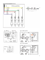
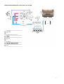
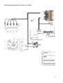
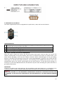
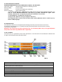
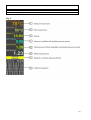
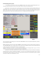
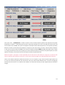
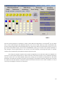
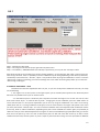
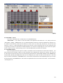
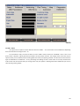
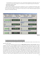
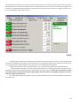
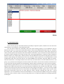
N.i.G.S. 01
N.i.G.S. 02
N.I.G.S. 02 /OBD
/OBD
INSTALLATION MANUAL LPG/CNG
SEQUENTIAL INJECTION SYSTEM
North Italy Gas Systems S.r.l.
Via Giuseppe Carcassola 32/34
20056 TREZZO SULL'ADDA (MI)
Tel: +39 0239526882 Mobile: +39
3421472001
[email protected]
www.nigsgas.it
Installation Manual
Revision 01 January 2011
INDEX
1. GENERAL RECOMMENDATIONS
- PAGE 3
2. CONNECTION OF THE INJECTORS CUT-OFF WIRING
- PAGE 3
3. INSTALLATION DIAGRAMS
- PAGE 4-10
4. OPERATION OF THE SWITCH
- PAGE 10
5. NIGS INTERFACE SOFTWARE
- PAGE 11
6. INTRODUCTION
- PAGE 11
7. SET UP MENU
- PAGE 11
8. PRESETTINGS OF THE SYSTEM
- PAGE 13
9. MANUAL ADJUSTMENT
- PAGE 17
10. DATA BASE MENU
- PAGE 18
11. CUSTOMER’S DATA MENU
- PAGE 18
12. MAP MENU
- PAGE 19
13. ADVANCED MENU
- PAGE 20
13. OBD/ CAN communication modul
- PAGE 22
14. SOME USEFUL HINTS
- PAGE 23
2
1.0 GENERAL RECOMMENDATIONS
• Before installing the gas system, disconnect the battery earth cable (unless specifi ed to the contrary
by the car maker).
Attention: this may delete the car radio and telephone memories and jam the centralised door locking and
anti-theft systems. In this case, you may connect the battery temporarily.
• Always smooth holes after drilling and apply anti-rust to the edges.
• Apply silicon to each cable through-hole to prevent water from entering the interior.
• Install the control unit as far away as possible from areas where water could infi ltrate, far away from heat
sources (e.g.: exhaust manifolds), far away from high-voltage cables and, wherever possible, with the
connector pointing downwards.
• If the fuse blows, do not replace it with one of a higher current rating.
• Do not attempt to open the control unit as this could cause irreparable damage. NIGS declines
all liability for injury to people or damage to property should its equipment be tampered with.
In this event the warranty shall also be invalidated.
• Always make electrical connections using the relative joints or soft solder them to prevent the
formation of false contacts.
• Always observe the current laws and/or regulations in the State where the LPG system is mounted.
• Remember that, as per the relative standards, all the assembly instructions refer to the driving position.
• Before mounting the electronic control unit, make sure the relative fuses are disconnected.
• Do not wash the engine after installation.
WARNING
FAILURE TO OBSERVE THE INSTRUCTIONS CONTAINED IN THIS MANUAL MAY CAUSE THE
SYSTEM TO WORK INCORRECTLY OR NOT WORK AT ALL. THIS MAY CAUSE DAMAGE TO
N.I.G.S. COMPONENTS AND INVALIDATE THE WARRANTY.
2.0 CONNECTION OF THE INJECTORS CUT-OFF WIRING.
Verify the polarity of the injectors acting as follows:
1. Disconnect all connectors of the original injectors.
2. Prepare a multimeter to measure the direct voltage with full range equal to 20V and connect the
negative lead to the ground.
3. Place the positive lead on one of the contacts of the connector injector.
4. Insert the panel and check on the multimeter the measured voltage value. If the reading is about
12V, that is the positive cable.
WARNING
FEEDING OF THE INJECTORS IS TIMED; THEREFORE, AFTER SOME SECONDS FROM SWITCHING ON
OF THE PANEL, IT IS DISABLED. IT IS SUGGESTED TO VERIFY THE POLARITY OF ALL INJECTORS,
SINCE SOME CARS HAVE AN INVERTED INJECTOR WITH REFERENCE TO THE OTHERS.
After having verified the polarity of the injectors, it is possible to connect the injector emulation harness.
Cut the petrol injector negative wire. The one of the wires have to be connected to the injectors; while the
other have to be connected to the gasoline injection control unit. Respect the matching between the sheath
of the injector emulator wiring and the gas injector.
In case of connection on a 3-cylinder car, the YELLOW wires have to be left disconnected.
3
3. INSTALLATION DIAGRAM N.I.G.S. 01
4
INSTALLATION DIAGRAM N.I.G.S. 01
5
INSTALLATION DIAGRAM N.I.G.S. 01
6
INSTALLATION DIAGRAM N.I.G.S 02 and N.I.G.S. 02 OBD
7
INSTALLATION DIAGRAM N.I.G.S 02 and N.I.G.S. 02 OBD
8
INSTALLATION DIAGRAM N.I.G.S 02 and N.I.G.S. 02 OBD
9
4. OPERATION OF THE SWITCH
The switch supplied with the kit is equipped with a push-button, LEDs, and an internal buzzer.
ITEM DESCRIPTION
1 PUSH BUTTON It is used to select the type of feeding (petrol or gas). By pressing it, it is possible
to switch from one type of fuel to the other.
2 [RED LED ON] Car running on petrol
3 [GREEN LED ON ] Car running on gas
4 [YELLOW LEDs] Quantity of gas in the tank
SWITCHING TO PETROL DUE TO GAS LOW PRESSURE
When the switch reaches the reserve and the gas pressure falls under a pre-set value, the control unit
switches automatically to the petrol feeding. This occurs to avoid that the engine can operate with a too
weak mixture damaging in this way the catalytic converter. Before switching again to the gas feeding,
perform a fuel filling. The switching to petrol due to GAS LOW PRESSURE is signaled by the switch with the
switching-on of the RED LED (petrol operation), and switching off the GREEN LED indicator and of the
YELLOW LEDs and by the acoustic warning given by the internal buzzer. To stop the buzzer buzzing it is
necessary to press the PUSH-BUTTON once; the RED led stays ON. After fuel filling the system will start on
gas mode automatically.
EMERGENCY
If the car is not able to start with petrol (e.g. due to problems on the petrol pump, etc.), it is possible to start
it directly on LPG. To do this, keep the switch push button pressed for 25 sec and than start the engine.
WARNING
DIRECT GAS STARTING IS TO BE CONSIDERED AN EMERGENCY OPERATION. ITS REPEATED USE CAN LEAD
TO DAMAGES TO THE CATALYTIC CONVERTER OR THE SWITCHINGON OF THE CHECK ENGINE WARNING
LAMP.
10
5.0 NIGS INTERFACE SOFTWARE
MINIMUM REQUIREMENTS OF THE COMPUTER TO INSTALL THE SOFTWARE
Operating system
- Windows 98 2nd edition or following versions
Memory (RAM)
- At least 16 MB
Hard disk
- At least free 20 MB upon installation
Screen resolution
- 1024 x 768 or higher
1. Install file "dotnetfx.exe". If Windows OS is older version and you can't install the program, you
have to install "WindowsInstaller.exe" after that try to install "dotnetfx.exe" again. Once
installed, "dotnetfx.exe" run anytime,no need to be installed for new versions.
2. Install USB driver "PL-2303 Driver Installer.exe".
3. Copy the file "NIGS.exe" into your computer and start it.
If the program doesn't connect with LPG ECU, please specify COM Port which is used for you, by
button "COM/Language".
6.0 INTRODUCTION
The calibration software can be opened without being necessarily connected to the control unit.
To connect to the control unit, it is instead necessary that the PC and the control unit are correctly
connected by a USB cable.
Moreover, the control unit has to be connected to the +12 volt battery (RED wire), to the ground (BLACK
wire) and to 12V under key (dashboard ON - engine OFF).
7.0 SET UP MENU
From this menu, it is possible to access main parameters in all sub-menus of the calibration software that
are given and individually described here below.
FIG.1
1 - Button LPG – it working when reducer temperature is reached /Blue active , Gray not active/
2 - Button Petrol – active when it is in yellow color and not active whne it is grey color
3 - Force GAS – you can switch immediately to LPG no matter of the temperature and sequence of the cylinders
4 - Petrol injection time in milliseconds (ms)
5 - LPG injection time in milliseconds (ms)
6 - Nozzles calculator
7 - Button for language and “COM Port” setting
8 – RPM meter
9 – RPM separator for full group and semi- sequent engines /if it is needed/
10 - Switch over separately the cylinders from GAS to Petrol and from Petrol to GAS (yellow - Petrol, blue - GAS)
11- Button for software update – click and follow instructions
11
12 - Communication between ECU and PC. Green light active, red light – no communication
13 – Hardware version information
14 - Software version information
15 – Default settings button
Fig. 2
12
8.0 Presettings of the system
It is necessary to select from the first menu “SET UP” number of the cylinders, approximately power in h.p.,
Fuel type, the type of temperature sensor of the reducer, Injector rail type, sensor delay time etc.
Level sensor - from this menu you can choose type of sensor and also adjust all 4 levels by sliders. Moving non
standardtype sensor you could adjust all 4 levels, measured in volts. On the screen aree shown the LED-s from the
switch - petrol, gas, reserve, 1/4, 1/2, ¾. When the level from multivalve is increasing and the voltage from the sensor is
decreasing, you have to choose “Non standard reverse sensor” The adjustment procedure is the same.
FIG.3
After completing the initial settings you can select menu SWITCHOVER in order to set proper temperatures, pressures,
times and switch over RPM.
RPM for automatic turnover from gas to petrol. (FIG.4) The system allows turn over from GAS to petrol over given by
slider (2000-8000 RPM). If the running on petrol car goes under the chosen RPM, the ECU turnover automatically to LPG
or CNG. Thes function is switched off when slider is in right end position.
Switchover RPM Petrol to Gas slider - you could choose the RPM when the cold engine starts on gas, it is for the
problem cars only for first switch-over. Basically this function is switched off.
Sometimes in cold weather (under 10oC) the injectors need to be moved primary to be ready to work properly
till became warmer, so there is procedure for regulation – the time in sec. for switching each cylinder on gas. This could
be made by slider in down right corner of the screen. In the same time for first turn over from petrol to gas it is provided
possibility for adjustment of the RPM when is done.
13
FIG.4
Then open menu – “DIAGNOSTICS” in order to check to correct cut-off of petrol injectors, their sequence and proper
temperatures. If there is a sequential type of control of the petrol injectors you’ll see on the left side of the screen and
on the bottom the real RPM, also you’ll see sequential movement of the colored squares for each cylinder separately.
When the control is parallel 2x2 /semi sequent/ or “full group” you’ll see it clearly on screen – Petrol injectors sequence.
In this case you have to switch the RPM to real values by using the checkbox RPM/2 in RPM meter /fig.1 No.8/. If there
is a missing coloured square for some cylinder you have to check the electrical connections for petrol injectors, if all the
squares are missing – you have to turn over the input connectors to petrol ECU side.
When the engine is “full group” or Semi sequential you must click also on the check box “Full group”. By that the LPG
injectors will inject fuel 2 times less (over tact). In this case you have use bigger size calibrated nozzles than standard.
There is also statistic information about the hours the car is run on petrol, on gas, also the cycles of gas injectors are
run, the hours left to the profilactic and maintenance. Here you could see two different times - from the very begining
and from the last control. It is useful for the installers to control the waranty and the elapsed time for the filter’s
change.
14
FIG.5
Until now all the operations are executed in “Petrol” mode. When the temperature is minimum 200С you can switch
over in “LPG” mode looking for the differential pressure to be near to 1.5bar. When you have normal RPM in idle,
pressure, working engine with increased temperatures over 700C on the reducer and at least 500С on LPG rail, you can
go to auto tuning mode. Anyway, from the menu “DIAGNOSTICS” (FIG.5) you can switch each cylinder separately on
LPG, looking for normal engine behavior in this case you can catch eventually not working LPG injector or improper
sequence which could be easy normalized by using the injector terminals.
The real sign for improper sequence of the cylinder arrangement you can find when switch-over LPG/Petrol or
vice versa in case the petrol injector times in “Petrol” mode and in LPG mode are equal. You can adjust this equality by
using the arrows near in the “FINE TUNING” (FIG.6) menu, waiting near 10 seconds and switching over a few times
Petrol/LPG. And if after this procedure the engine is still shaking for a second when switchover the fuels you must check
the sequence of the LPG injectors. Rarely the mistake could be from the hoses row to intake manifold, it is easy to
correct by rearranging the connectors on the LPG rail.
15
FIG.6
To facilitate users in menu "Fine Tuning" are added several functional buttons on the graph of coefficients - red and
blue triangle buttons which allow adjustment in five points of the graph.
By them in different areas (Low, medium and high) of the motor loads you can smoothly regulate rates.
From left to chart is added slider, which is carried out by moving the entire schedule all coefficients by vertical. Activate
slider by double click on the chart.
If the engine is working well you can go to “Autotuning mode” (FIG.7). It has to be done when all the power consumers
are switched off (A/C, window, seat and mirror heaters, lights, cooling fan of the radiator). The engine must reach
minimum 600С and you have to sure by the lambda sensor data that the petrol ECU regulates. Than the AUTOTUNING
procedure can start by pressing the button. Follow the instructions in a few steps that will appear in red colour in the
fileld.
16
FIG.7
Step 1 - Calibration at idle mode.
Step 2 - Force engine several times (5-6) to get maximum petrol times.
Step 3 - reach 3000 +/- 500 RPM without load and keep it permanent, you can push the “next step” button.
After 20-50 seconds in the dark field you’ll see the number between 1-2.5 and message “OK” under it, which means the
auto tuning is finished. There is a possibility to choose 3 different ways of driving depending on the driver’s preferences,
conditionally called “Economic”, “Normal”, “Sport”. They could be chosen by using the checkboxes in screen. In case the
“Auto tuning” mode is not working, you’ll see the message into screen. After eliminating the problem you can start the
“Auto tuning” mode again.
9.0 MANUAL ADJUSTMENT – FIG.8
Sometimes the automatic adjustment does not pass, so you have to adjust the coefficients manually. The steps
are the following:
1. The engine runs on idle in petrol. In the upper square you see moment petrol injection time. When the petrol
ECU starts vary lambda sensors you can switch on LPG.
2. In the bottom square is shown the petrol injection time when the engine runs on LPG. You have to reach
both values almost equal – it could be done by slider - changing the current coefficient, push the “SAVE” button to
record into the ECU. For more precise adjustment you can do it by using the coefficients in the menu ”Fine tuning”
/FIG.9/ when the car is moving on different road types, to ensure more loads for the engine and speeds. In the menu
you have push button “calculate map”. This is the connection between the linear adjustment with coefficients and the
3-size map, which is table of coefficients, depending from petrol time and RPM. This button gives you possibility to
switch from easy to more detailed adjustment. Driving the car with constant RPM and gas pedal (fixed TPS), you see the
blue line on the petrol inj. time. You have to switch from petrol to LPG and move with arrows up or down current
coefficient till the valve, when the petrol inj. time is equal on petrol and LPG running. The same procedure for different
17
petrol times will give you more precise adjustment. By arrows of the neighbour coefficients you have to adjust them so,
the red curve is slight falling down to the high /FIG.9/.
FIG.8
You also have to make fine tuning when you notice the change in the way of working of the engine (loosing
power or increasing the consumption of LPG fuel).
From the “FINE TUNING” (FIG.9) menu use the checkbox labeled “Normal”. On the screen you see coefficients; the
working in each moment is colored in RED point. Ensure permanent load, RPM and throttle position (gas pedal) switchover from “Petrol” to “LPG” and if the petrol injector times are changing, correct the colored in blue coefficient
simultaneously with switching over. If the petrol time when turn over from “Petrol” to “LPG” is increased you have to
increase the coefficient and vice versa till you reach the equality of these petrol times. It is recommended to use this
procedure for more load conditions of the engine (at least 6-10). If you didn’t manage to cover all driving modes using
the arrows adjust all uncalculated coefficients near to the calculated ones. Looking over the curve, you’ll try to make
this curve smoother.
18
FIG.9
10. “DATA BASE” – FIG.10
This screen is devided in two: “AUTO DATA” and “CUSTOMER DATA”
“AUTO DATA” – if you want to create new folder with adjustment information for a car, after you fill lines
“Automobile”, “Model”, “ENGINE TYPE” etc., by “SAVE AUTO DATA” button you could save the details for the given car,
the software automatically creates the fails with the names of the car (Ford, Opel, Honda etc). The fails are with
extension “*.LPG” or “*.CNG” depending on the first menu “SET UP”. So the created fails you can use to adjust the next
car types from previous ones. By button “LOAD AUTO DATA” you choose corresponding fail, on the screen will appear
button “LOAD in the ECU” and by pressing it you can load the adjustment parameters into the ECU.
11. “CUSTOMER’S DATA”:
After the adjustment of the system is made it is possible to save the information for about the customet. You
have to fill the lines, by button “SAVE” you save information into a different file, useful for the installer. The names of
the files with the data about the client are automatically generated like “CAR, BRAND, MODEL, PLATE NUMBER (for
example OPEL_VECTRA_CA1234XB) which data you can change for your needs. The fails are with extension *.CNT and
they are saved in subdirectory “CUSTOMER DATA”. On the time of maintenance of the LPG/CNG systems you can open
the fails by button “CUSTOMER DATA” and to refer the adjustment for the car and the client’s data – like “kilometres”,
“installing data” etc.
19
FIG.10
12. MAP – FIG.11
The system has an option to work with the three size “MAP” – it is the function of the coefficients depending
from the revolutions and engine load – ms.
To work with the map, you have to switch to menu “MAP” and the check box “USE MAP”. There is also a red
point, which is dynamic, signing the three parameters at the present moment. The change of the cell of the map or
square of cells you can make by mouse marking (with blue colour) and pushing “ENTER”. You will see the small menu for
type of modification of coefficients – linear, percentage and adding of value. These values in the map could be from
1.00 to 2.50. Each of the time when you change some cells, the system is working with these coefficients you have to
save them by pushing “SAVE”.
20
FIG.11
13. ADVANCED MENU
In this menu you can set up the following features:
- Teperature for direct ingnition on gas
- Slider for adjustment of minimum gas time for engines with not stable RPM at idle mode. For the most popular
injectors VALTEK and RAIL or similar this time is 3.8ms
- Gas injector start pulse length For the injectors with different coil resistance (1, 1.5, 2, 3ohm) the lenght of the
start impulse must be precisely adjusted, so by this slider you could readjust the necessary time for
correspond coil resistance (basically in the system are given 3 ohm coils and factory set time is 3.78ms., you
don’t need to use this function). For some cars with very short petrol injector times (up to 2.2ms) the coils
could be changed with 1.5 or 2ohm coils) in this case the system performance could be better. The times to
be choosen are as follow: 1ohm - 2.5ms; 1.5 - 2.8ms; 2ohm - 3.2ms.
- HOLDING coefficient - specific setting for non standard injectors (10 Ohm withoout PWM). Use factory settings
10% +/- 2%.
- Slider decrease gas pressure after continuous “CUT OFF” mode for the engine, or for the “turbo” engines,
which consume a lot of gas, also for the cars with big power (over 150 PS) with automatic transmissions,
which are put often in “kick down” mode. First slider determines how much seconds you have to let the gas
21
off. (Sometimes if you choose the times over 5 sec., the petrol ECU could light the “Check engine” lamp, so
this function must be used very carefully. The second slider is used to adjust the length of the let off cycle.
- Time between cleaning cycles
- Time to next maintenance
Last two sliders for adjusting of the the time to maintenance in hours. It is establised also the feature, which
allows clean the petrol injectors automatically on the time the machine is running on gas. This is very useful for
the cars with very big mileage, such as taxi cars or fast courier cars. There is slider, which adjust the period
between one minute petrol cleanning.
FIG.12
14. OBD/ CAN communication modul – ONLY FOR NIGS02 OBD
This chapter will give more information about the OBD/ CAN communication modul and will direct to easy
adjustment of the system.
First of all you could see two screens in the menu “OBD parameters” (Pic.13) and “Errors” (Pic.14) . When the
instalation of the wires, used for OBD/CAN connection are properly spliced to the back wires of the car’s 16-pin
diagnostic connector, running the software you have to connect gas ECU by pushing the button “OBD connect”. After a
few seconds you will see a message “OBD connected”. By pushing some of the red buttons you could see the moment
value of some important parameters, reading from the petrol ECU. The most important ones are “Short fuel trimmer
and “Long fuel trimmer” (in %), which correspond to the right adjustment of the system. For convenience you will see
these parameters also on the proper place in the menu “ Fine adjustment”. Shortly you have to know, that you need to
keep them near to 0%. If their values are very different from 0% at petrol, you need to readjust the koefficients in gas
mode so, that the values of these both parameters have to be equal to them in petrol mode (for instance at petrol
mode they are +18%, adjust the coefficients this way, they are near +18% in gas mode). Here is the place to mention
22
what these two parameters mean. If they are permanently positive (+..% ),it means the fuel mixture is too lean and the
petrol ECU will try to encrease the injection times to compesate this. If the sign for them is most the time negative, the
mixture is rich. Most often these parameters are positive when the petrol injectors are dirty or negatjve when the car is
run over 100 000 km or the air filter is dirty.
FIG.13
Analizing these parameters you could find some problems in the gas system in whole. For instance after 30-60
thousand km meleage the gas injectors increase the flow rate, so the gas ECU make the fuel mixture rich and the “short
and long fuel trimmer” became negative. In this case you have to readjust the coeff. properly.
Looking other parameter ( for inst. Intake pressure ), you could control the proper work of the MAP sensor.
The other mode in the menu is “Errors” /FIG.14/. Using this menu, you could read, analize and clear all errors,
established on the time of installing, adjusting and using the gas system any time. NOTE: Here is important to inform
you, that you have to clear the errors after carefull analisys. In some countries it is forbidden to do this. So you must
to be very careful with this feature!
It is very useful to make easy diagnostic, using our system software when you make maintenance control for the
gas system at all.
23
FIG.14
15. SOME USEFUL HINTS
These notes will give you information about the possibility to adjust the system, installed on the cars with some
special features, like “full group”, short injection times etc.
First we need to explain the thresholds, where the system working properly. For the coefficients they are
between 1.0 and 2.5. It is means, that all the petrol injection times will be multiplied with these values. For instance if
the current coeff. is 1.8 and the petrol time at idle is 1.9ms, the gas injection time will be 3.42ms. Here is the place to
inform, that the injectors work properly with times between 4.0 and 24ms. So you could see from upper exercise how
the system could be adjusted out of range of proper work. All the good adjustment is related to proper combination
between nozzle’s size, multiply coeff., reducer pressure and map adjustment. Every time the long hoses (over 25 cm.)
and the remote drilling into manifold (more than 3cm.) away from petrol injectors are not permitted due to avoid
unstable work at idle. Let us to see one exercise – for instance BMW 2.5i car old model – full group, 1994, 6 cyl., 192 PS.,
automatic transmission. According to table for the nozzle sizes, we could choose 2 mm nozzle. Because this car is “full
group” car, by check box on the diagnostic screen we switch to this mode. In this case we increase the nozzle size to 2.5
mm and start the auto-tuning mode. If the self-adjusting is OK, the owner could test the car on the road in all regimes –
middle speed, big speed with low rpm, kick- down mode of the transmission, etc. Often in the high rpm mode (over
4500 rpm) the engine need more fuel, so you could increase the coefficients near the place of the blue band – current
injection time. Every time we have to be careful with the value of the gas times( green) – not more 22- 24 ms at 5000
rpm. Sometimes for better performance we could switch over 5000-5500 rpm by slider engine to work on petrol. If the
auto-tuning mode doesn’t pass OK, we could adjust the system manually, switching the check box “ manual
adjustment”. In this case follow the manual recommendations. For many reasons the software could give the message
in the note screen ( red color ) which is not correct ( big nozzles, etc.), we adjust the coefficients according to good work
of the engine.
24
Sometimes, for the cars with bigger power and especially with automatic transmission (40-60 PS/cylinder), we
need to increase the coefficients for middle and high loads (over 8-10 ms) with 10-40 % at least, so in this way the coeff.
curve on the “Fine tuning” screen become with smaller slope and even horizontal flat. It is make by automatic
calibration (self tuning) and later manually.
For the “full group” cars with small petrol injector times (less than 2.2ms) you have to be careful haw to
choose the calibrating nozzles, to ensure coeff. at idle at least 1.9 – 2.1. Because in ”full group” mode we inject the gas
two times less than petrol, the nozzles must be at least two sizes bigger, than in normal mode ( the check box “full
group” on the diagnostic screen must be switched on). In these cars could be seen other problem – at high speed, big
rpm (over 4500) and TPS over 50-60% the bad, interrupting performance of the engine is seen. It is because of the
totally open gas injectors at this regime. It could be avoid by decreasing of multiply coeff. ( the gas times must be under
22-24 ms at 5500-6000rpm). It is going against the requirement for the big coeff. at idle, so we need to find the right
“middle”. In these cases sometimes is more difficult to stabilize the rpm at idle. Very rarely we have to do this by using
more fast injectors (with opening time not more, than 2.5ms – the standard ones are around 3.5-4 ms.) If it is not
possible, the MAP adjustment could be useful. We have to adjust the system by auto-tuning procedure, after that by
buttons “Calculate MAP” and “Use MAP” we open the MAP screen, where it is seen the red point, moving into 4-6
fields. Marking them, changing the values up or down between 10-20% we could stabilize the rpm at idle. Very often
the length of the pipes to manifold have to be shortened less, than 20 cm. to stabilize the idle rpm.
25