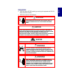
1
English
IND560
Terminal
Installation Manual
No part of this manual may be reproduced or transmitted in any form or by any
means, electronic or mechanical, including photocopying and recording, for any
purpose without the express written permission of METTLER TOLEDO.
U.S. Government Restricted Rights: This documentation is furnished with
Restricted Rights.
Copyright 2005 METTLER TOLEDO. This documentation contains proprietary
information of METTLER TOLEDO. It may not be copied in whole or in part
without the express written consent of METTLER TOLEDO.
METTLER TOLEDO reserves the right to make refinements or changes to the
product or manual without notice.
COPYRIGHT
®
METTLER TOLEDO is a registered trademark of METTLER TOLEDO. All other
brand or product names are trademarks or registered trademarks of their
respective companies.
METTLER TOLEDO RESERVES THE RIGHT TO MAKE REFINEMENTS
OR CHANGES WITHOUT NOTICE.
FCC Notice
This device complies with Part 15 of the FCC Rules and the Radio Interference
Requirements of the Canadian Department of Communications. Operation is
subject to the following conditions: (1) this device may not cause harmful
interference, and (2) this device must accept any interference received, including
interference that may cause undesired operation.
This equipment has been tested and found to comply with the limits for a Class
A digital device, pursuant to Part 15 of FCC Rules. These limits are designed to
provide reasonable protection against harmful interference when the equipment
is operated in a commercial environment. This equipment generates, uses, and
can radiate radio frequency energy and, if not installed and used in accordance
with the instruction manual, may cause harmful interference to radio
communications. Operation of this equipment in a residential area is likely to
cause harmful interference in which case the user will be required to correct the
interference at his or her own expense.
Declaration of conformity is located on the documentation CD.
English
© METTLER TOLEDO 2005
•
READ this manual BEFORE operating or servicing this equipment and FOLLOW
these instructions carefully.
•
SAVE this manual for future reference.
WARNING!
FOR CONTINUED PROTECTION AGAINST SHOCK HAZARD CONNECT TO
PROPERLY GROUNDED OUTLET ONLY. DO NOT REMOVE THE GROUND
PRONG.
CAUTION
BEFORE CONNECTING/DISCONNECTING ANY INTERNAL ELECTRONIC COMPONENTS OR
INTERCONNECTING WIRING BETWEEN ELECTRONIC EQUIPMENT ALWAYS REMOVE POWER
AND WAIT AT LEAST THIRTY (30) SECONDS BEFORE ANY CONNECTIONS OR
DISCONNECTIONS ARE MADE. FAILURE TO OBSERVE THESE PRECAUTIONS COULD RESULT
IN DAMAGE TO OR DESTRUCTION OF THE EQUIPMENT AND/OR BODILY HARM.
CAUTION
OBSERVE PRECAUTIONS FOR HANDLING ELECTROSTATIC SENSITIVE DEVICES.
WARNING!
A. NOT ALL VERSIONS OF THE IND560 ARE DESIGNED FOR USE IN
HAZARDOUS (EXPLOSIVE) AREAS. REFER TO THE DATA PLATE OF THE
IND560 TO DETERMINE IF A SPECIFIC TERMINAL IS APPROVED FOR USE
IN AN AREA CLASSIFIED AS HAZARDOUS BECAUSE OF COMBUSTIBLE OR
EXPLOSIVE ATMOSPHERES.
WARNING!
WHEN THIS EQUIPMENT IS INCLUDED AS A COMPONENT PART OF A
SYSTEM, THE RESULTING DESIGN MUST BE REVIEWED BY QUALIFIED
PERSONNEL WHO ARE FAMILIAR WITH THE CONSTRUCTION AND
OPERATION OF ALL COMPONENTS IN THE SYSTEM AND THE POTENTIAL
HAZARDS INVOLVED. FAILURE TO OBSERVE THIS PRECAUTION COULD
RESULT IN BODILY HARM AND/OR PROPERTY DAMAGE.
English
PRECAUTIONS
Contents
Introduction ................................................... 1-1
IND560 Terminal Versions .......................................................... 1-1
Warnings and Precautions .......................................................... 1-2
Operating Environment................................................................ 1-3
Inspection and Contents Checklist ................................................ 1-3
Model Identification .................................................................... 1-4
Physical Dimensions .................................................................. 1-5
Specifications ............................................................................ 1-7
Main PCB.................................................................................. 1-8
Options ..................................................................................... 1-9
Scale Bases...................................................................................1-9
Discrete I/O....................................................................................1-9
Ethernet/Serial Ports......................................................................1-10
PLC Interfaces ..............................................................................1-10
Fill-560 (Application Software) ......................................................1-11
InSite™ Configuration Tool..............................................................1-11
Chapter 2.0
Installation...................................................... 2-1
Opening the Enclosures .............................................................. 2-1
Panel-Mount Enclosure ...................................................................2-1
Harsh Enclosure.............................................................................2-2
Mounting the Terminal ................................................................ 2-2
Panel-Mount Enclosure ...................................................................2-3
Harsh Enclosure.............................................................................2-4
Installing Cables and Connectors ................................................. 2-7
Ferrites ..........................................................................................2-7
Harsh Enclosure Cable Glands.........................................................2-7
Main Board Wiring Connections .......................................................2-8
Wiring Connections for Options ......................................................2-13
PCB Switch Settings.................................................................. 2-19
Main PCB Switches.......................................................................2-19
Discrete I/O (Relay) Switch ............................................................2-20
PCB Jumper Positions .............................................................. 2-21
Main PCB Jumper ........................................................................2-21
Sealing the Enclosure ............................................................... 2-22
External Sealing of the Panel-Mount Enclosure.................................2-22
External Sealing of the Harsh Enclosure ..........................................2-23
Internal Sealing of Both Enclosure Types .........................................2-24
English
Chapter 1.0
IND560 Technical Manual
For your notes
English
Chapter 1.0
Introduction
This chapter covers
•
IND560 Terminal Versions
•
Warnings and Precautions
•
Operating Environment
•
Inspection and Contents Checklist
•
Model Identification
•
Physical Dimensions
•
Specifications
•
Main PCB
•
Options
Thank you for purchasing the IND560 industrial terminal—the
latest in METTLER TOLEDO technology and the most versatile
weighing terminal available today. The IND560 terminal is a
high-performance single- or multiple-range weighing terminal
for use with analog load cells or high-precision IDNet scale
interfaces used in industrial automation applications.
For information about operation, configuration, service and
maintenance, and other technical specifications, refer to the
IND560 Technical Manual. For information about typical
IND560 terminal operation, refer to the IND560 User’s Guide.
IND560 Terminal Versions
The IND560 terminal is available in the following versions:
•
Harsh enclosure with analog load cell connection
•
Harsh enclosure with high-precision (IDNet) base connection
•
Panel-mount enclosure with analog load cell connection
•
Panel-mount enclosure with high-precision (IDNet) base connection
Standard IND560 Features
• Basic weighing terminal used in safe areas
•
Panel-mount or harsh desk/wall-mount enclosures
•
Connect one analog load cell scale base (or up to eight 350 ohm load cells)
or an IDNet base depending upon the version of the IND560
•
128 × 64 dot-matrix graphic vacuum fluorescent display (VFD) with
21mm-high weight display
•
Real-time clock (battery backup)
•
One serial port for asynchronous, bidirectional communication and print output
•
85–264 VAC power input range
1-1
IND560 Installation Manual
•
Support of the following option boards:
–
Analog Output interface
–
PROFIBUS-DP interface
–
Ethernet and dual serial ports
–
Discrete I/O interface
–
Allen Bradley RIO interface
•
Basic weighing functions including zero, tare, and printing
•
Selectable over/under classifying mode of operation with graphics
•
Selectable material transfer mode for simple filling or dosing
•
SmartTrac™ graphical display
•
Two memory tables—25 tare memories and 25 target memories
•
Unit switching between three different units including custom units
•
Alibi memory storage for up to 60,000 records
•
Grand total and subtotal registers for accumulating weight
•
Five customizable print templates and report printing
•
TraxDSP™ digital filtering for analog load cells
•
TraxEMT™ performance monitoring and recording
•
CalFREE™ calibration without test weights
For information regarding METTLER TOLEDO Technical Training contact:
METTLER TOLEDO US
1900 Polaris Parkway
Columbus, Ohio 43240
Phone (US and Canada): (614) 438-4511
Phone (International): (614) 438-4888
www.mt.com
Warnings and Precautions
Please read these instructions carefully before putting the new terminal into operation.
Before plugging in the terminal, make sure that the voltage stated on the terminal's
label matches the local power supply voltage. If this is not the case, do not
connect the terminal under any circumstances.
Although the IND560 is ruggedly constructed, it is nevertheless a precision
instrument. Use care in handling and installing the terminal.
1-2
IND560 Installation Manual
English
Operating Environment
When selecting a location:
•
Choose a stable, vibration-free surface
•
Ensure there are no excessive fluctuations in temperature and no direct
exposure to sunlight
•
Avoid drafts (for example, from fans or air conditioning)
•
Readjust (calibrate) the terminal after any major change of geographical
position
Temperature and Humidity
The IND560 can be operated at temperatures and relative humidity conditions as
listed under Operating Environment in Table 1-2. The terminal can be stored at
temperatures ranging from –20° to 60° C (–4° to 140° F) at 10 to 95% relative
humidity, non-condensing.
Environmental Protection
Panel-mount front panel sealing provides type 4 and type 12 protection—
comparable to IP65 rating (UL approval pending). The harsh enclosure meets
IP69K requirements (approval pending).
Hazardous Areas
Not all versions of the IND560 can be operated in areas classified as Hazardous
by the National Electrical Code (NEC) because of the combustible or explosive
atmospheres in those areas. Contact an authorized METTLER TOLEDO
representative for information about hazardous applications.
Inspection and Contents Checklist
Verify the contents and inspect the package immediately upon delivery. If the
shipping container is damaged, check for internal damage and file a freight claim
with the carrier if necessary. If the container is not damaged, remove the IND560
terminal from its protective package, noting how it was packed, and inspect each
component for damage.
If shipping the terminal is required, it is best to use the original shipping container.
The IND560 terminal must be packed correctly to ensure its safe transportation.
The package should include:
•
IND560 Terminal
•
InSite CD (PC configuration tool)
•
Installation manual
•
Bag of miscellaneous parts
•
Documentation CD (includes all manuals)
1-3
IND560 Installation Manual
Model Identification
The IND560 model number is located on the data plate on the back of the terminal
along with the serial number. Refer to Figure 1-1 to verify the IND560 that was
ordered.
Model IND560
Enclosure/Display Type
Scale
Always 000
Ethernet/Serial ports
Local I/O
Connectivity Option
Application Software
Module
Line Cord, Plug
Region/Language/ Character
56
H
4
0
0
0
0
B
P
F
0
B
00
00 – English,
Spanish, French,
German, and
Italian
0 - Panel enclosure, 100 - 240 VAC, no plug
A - 120 VAC, US Plug
B - 230 VAC, Schuko Plug
C - 240 VAC, UK Plug
D - 240 VAC, Australian Plug
E - 230 VAC, Swiss Plug
F - 230 VAC, Danish Plus
G - 220 VAC, US Plug
H - 230 VAC, India Plug
0 - No Module
0 - Basic Functionality
F - Fill-560
0 - None
A - Analog output
B - A-B Remote I/O
P - Profibus (panel enclosure)
R - Profibus (harsh enclosure)
0 - None
B - Local Discrete I/O, Relay
0 - None
A – Ethernet/Dual Serial Ports
0- None
1 - Single ALC, Standard
4 - IDNet Standard
H - Harsh, Graphic VFD
P - Panel, Graphic VFD
Figure 1-1: IND560 Model Identification Numbers
1-4
IND560 Installation Manual
English
Physical Dimensions
The IND560 terminal physical dimensions for the panel-mount enclosure are
shown in Figure 1-2 in inches and [mm].
Figure 1-2: IND560 Panel-Mount Enclosure Dimensions
The IND560 terminal physical dimensions for the panel cutout are shown in Figure
1-3 in inches and [mm].
Figure 1-3: IND560 Panel-Mount Cutout Dimensions
1-5
IND560 Installation Manual
The IND560 terminal physical dimensions for the harsh desk/wall-mount enclosure
are shown in Figure 1-4 in inches and [mm].
Desk-Mount
Wall-Mount
(with optional brackets)
Figure 1-4: IND560 Harsh Desk/ Enclosure Dimensions
1-6
IND560 Installation Manual
English
Specifications
The IND560 terminal conforms to the specifications listed in Table 1-2.
Table 1-2: IND560 Specifications
IND560 Specifications
Enclosure Type
Panel-mount stainless steel front panel with an
aluminum frame
Harsh environment desk/wall/column-mount type 304L
stainless steel enclosure
Dimensions (l × w × d)
Panel Mount: 265 mm × 160 mm × 92 mm
(10.4 in. × 6.3 in. × 3.6 in.)
Harsh Environment: 265 mm × 160 mm × 170 mm
(10.4 in. × 6.3 in. × 6.7 in.)
Shipping Weight
3.5 kg (8 lb)
Environmental Protection
Panel-mount front panel sealing provides type 4 and
type 12 protection—comparable to IP65 rating (UL
approval pending).
Harsh Environment meets IP69K requirements (UL
approval pending)
Operating Environment
The terminal (both enclosure types) can be operated at
temperatures ranging from −10° to 40° C (14° to 104°
F) at 10% to 95% relative humidity non-condensing.
Hazardous Areas
Not all versions of the IND560 can be operated in areas
classified as Hazardous by the National Electrical Code
(NEC) because of the combustible or explosive
atmospheres in those areas. Contact an authorized
METTLER TOLEDO representative for information about
hazardous applications.
Power
Operates at 85–264 VAC, 49–61 Hz, 750 mA (both
enclosure types).
Panel-mount version provides a terminal strip for AC
power connections.
Harsh environment version includes a power cord
configured for the country of use.
Display
128 × 64 dot-matrix graphic VFD display, 21 mm
Display Update Rate: 10/second
Weight Display
Displayed resolution of 100,000 counts for analog load
cell scales
Display resolution for high-precision IDNet bases is
determined by the specific base used
1-7
IND560 Installation Manual
IND560 Specifications
Scale Types
Analog load cells or
IDNet, High-Precision K Line (T-Brick type standard)
Number of Cells
Eight 350-ohm load cells (2 or 3 mv/V)
Number of Scales
Interface for one analog or one IDNet scale
Analog/Digital Update Rates
Internal: Analog: >366 Hz; IDNet: determined by base;
Target Comparison: 50 Hz;
PLC Interface: 20 Hz
Load Cell Excitation Voltage
10 VDC
Minimum Sensitivity
0.1 microvolts
Keypad
25 keys; 1.22-mm thick polyester overlay (PET) with
polycarbonate display lens
Communications
Serial Interfaces
Standard: One serial port (COM1)
RS-232/RS-422/RS-485, 300 to 115,200 baud
Optional Ethernet/Serial Ports: Ethernet 10 Base-T with
two additional serial ports (COM2 and COM3)
Protocol
Serial Inputs: ASCII characters, ASCII commands for
CTPZ (Clear, Tare, Print, Zero), SICS (most level 0 and
level 1 commands)
Serial Outputs: Continuous or Demand with up to five
configurable print templates or SICS host protocol, report
printing, interfaces with external ARM100 Input/Output
modules and DeviceNet Bridge
Approvals
Weights and Measures
USA: NTEP Class II, 100,000 d; Class III/IIIL,
10,000 d, CoC #05-057
Canada: Class III, 10,000 d, approval pending
Europe: OIML; Class II, III, 7,500 e, TC 6812
Product Safety
UL, cUL, CE
Main PCB
The IND560 terminal’s main printed circuit board (PCB) provides the scale
interface for analog load cell or IDNet.
The main board also contains the COM1 serial port that provides RS-232, RS-422,
or RS-485 communication. The port is bidirectional and can be configured for
various functions such as demand output, SICS host communications, continuous
output, ASCII command input (C, T, P, Z), ASCII character input, report printing,
totals printing, or connection to a remote ARM100 module.
The main board also contains the AC power input connections, keyboard interface
and bus connectors for the option boards.
1-8
IND560 Installation Manual
Scale Bases
English
The IND560 supports two types of scale bases: Analog or IDNet.
Analog Load Cell Scale Base
The IND560 supports this scale type by an analog load cell interface. The terminal
can drive up to eight 350-ohm analog load cells.
IDNet™ Scale Base
The IND560 supports the newer T-brick style of high-precision base through the
main board IDNet port. This port provides the +12 volts and communication
required to operate this newer style base. The older K module and Pik-brick cells
require the addition of an adapter board and new power supply (to support the
+32 volt requirement) to the IND560. The adapter board and power supply are
available as an option.
Options
The following options are available for the IND560:
•
Discrete I/O
–
Internal, high-level discrete I/O (4 inputs and 6 outputs)
–
Remote discrete I/O via ARM100 module
•
Ethernet/Dual Serial Ports
•
Programmable Logic Control (PLC) interfaces, including:
–
Analog Output
–
Allen-Bradley® (A-B) RIO
–
PROFIBUS® L2DP
•
Fill-560 (application software)
•
Installation kit for older pre-2003 high-precision bases using a Pik-Brick weigh cell
•
InSite™ Configuration Tool
•
Various brackets for wall and column mounting of the harsh enclosure
Discrete I/O
The discrete I/O interface options include both internal and remote I/O.
•
The internal version is available with dry-contact relay outputs. The relay
contacts will switch up to 30 volts DC or 250 volts AC. The inputs are switch
selectable as either active (for simple pushbutton control) or passive (for
connection to PLCs or other devices that supply their own power for the I/O).
1-9
IND560 Installation Manual
•
The remote I/O is supported with the ARM100 remote module that provides
dry-contact outputs. The inputs are passive on the ARM100. An external
24-volt DC supply is required to operate the ARM100.
•
A total of 12 inputs and 18 outputs are supported through a maximum of three
options.
Ethernet/Serial Ports
The Ethernet port can be used for FTP transfer of tare and target tables and
complete setup files. It also provides a TCP/IP port to transmit a demand template
or continuous data for remote configuration using the METTLER TOLEDO InSite™
program, and for direct access to data via a shared data server.
COM2 provides RS-232 communication at rates from 300 to 115.2k baud. COM 3
supports the same baud rates and provides an RS-232, RS-422, or RS-485
connection.
PLC Interfaces
The IND560 PLC interface options include Analog Output, A-B RIO, and PROFIBUS
L2DP.
Analog Output
Analog Output refers to the representation of an internal system variable using a
proportional electrical signal. Analog Output can be used to transmit a measured
value, such as the gross or net weight. Another use for Analog Output is as a
control signal for some external device, such as a control valve, where the amount
of valve opening is proportional to the analog signal commanding its operation.
Such outputs are used to control the flow rate of material into or out of a vessel.
Both 0-10 volt DC and 4-20 mA signals are provided.
A-B RIO
The A-B RIO option enables data exchange by bi-directional communications using
the Discrete Data Transfer or Block Transfer mode. The IND560 Terminal initiates a
communication exchange with the PLC approximately 20 times per second
utilizing the Allen-Bradley Discrete Data Transfer protocol. This communication is a
high-speed, real-time message interface between the IND560 Terminal and the
PLC for process control. Division, integer, and floating point values are supported.
The IND560 A-B RIO interface also supports Block Transfer mode for transmission
of larger amounts of data. Additional details of this interface can be found in the
IND560 PLC Interface Manual on the documentation CD.
PROFIBUS L2DP
The IND560 Terminal communicates to a PROFIBUS-DP master according to
DIN 19 245. The PROFIBUS option consists of a module and software that resides
in the IND560 Terminal, which implements the data exchange.
1-10
IND560 Installation Manual
The Fill-560 is a special application that can be added to the IND560 terminal to
provide additional filling and dosing control. It provides control for the following
combinations of weigh-in and weigh-out sequences.
•
Fill only
•
Blend only
•
Fill and dump
•
Blend and dump
•
Dose out only
•
Blend and dose out
•
Fill and dose out
Additional information can be found in the Fill-560 Manual on the documentation CD.
InSite™ Configuration Tool
The IND560 terminal can connect to a PC running InSite via the IND560 COM1 or
optional Ethernet ports to provide the following:
•
Viewing and/or changing configuration from a remote PC
•
Enabling device-free configuration work before hardware installation
•
Saving configuration information locally on the PC, loading a saved
configuration file into other devices, or restoring to a known state for service
purposes
•
WYSIWYG editing tool with expanded viewing area, cut/paste functions, stored
clipboard library (MyData items), and template space usage display
•
Printing documentation of configuration for users’ records
•
Performing firmware upgrade services for the IND560
Display and Keyboard
The IND560 terminal has a Vacuum Fluorescent Display (VFD), 128 × 64 dot
matrix graphic type display.
The display shows a system line at the top of the display for system messages and
data; application area with weight display, legends, data entry, and other
information in the middle; and softkey labels (icons) across the bottom.
The display layout is designed with a system line reserved at the top to show
system messages and any asynchronous errors. The middle portion of the display
is reserved for the weight display and/or SmartTrac display. Random data entry is
shown in the bottom of this area. The bottom of the display is reserved for showing
the graphic labels (icons) for the softkeys. Display positions for up to five softkey
icons are provided.
1-11
English
Fill-560 (Application Software)
IND560 Installation Manual
To the right of the softkey icon area is a reserved space for a MORE UP ( ) or a
MORE DOWN ( ) indicator. If present, these indicate additional softkey selections
are available by pressing either the UP or DOWN navigation keys. A total of 15
softkeys are programmable for the home position depending upon the weighing
options and terminal functions enabled. These are presented in three sets of five
softkeys. The softkey setup and key mapping capabilities of the terminal determine
the positioning of the softkeys and locations where they display.
Three dedicated scale function keys are located to the right of the display. These
provide the interface to zero or tare the scale and to initiate a print.
The terminal’s 12-key numeric keypad is used to enter data and commands. The
numeric keys are located on the upper-right side of the terminal front panel.
Five navigation keys are located below the three scale function keys. These keys
enable the operator to navigate through setup options in the menu tree and within
setup and application screens.
Figure 1-5 shows the IND560’s display and keyboard layout.
Figure 1-5: The IND560 Display and Keyboard Layout
1-12
Chapter 2.0
Installation
This chapter covers
•
Opening the Enclosures
•
Mounting the Terminal
•
Installing Cables and Connectors
•
PCB Switch Settings
•
PCB Jumper Positions
•
Sealing the Enclosure
This chapter provides installation instructions for the IND560
terminal panel-mount and harsh enclosures. Please read this
chapter thoroughly before beginning installation.
Opening the Enclosures
Procedures for opening the IND560 terminal panel-mount and harsh enclosures
differ and are described in the following sections.
Panel-Mount Enclosure
The panel-mount version of the IND560 is opened by removing the three
Phillips-head screws on the back panel (see Figure 2-1). The rear panel can then
be removed to gain access to the internal workings of the terminal.
Phillips-head
screws on the
back panel
Figure 2-1: Opening the Panel-Mount Enclosure
2-1
IND560 Installation Manual
Harsh Enclosure
The front panel of the harsh enclosure IND560 terminal is locked in place by four
spring clips attached to the enclosure body. To gain access to the terminal’s PCB
for internal wiring and setting switches, separate the front panel from the enclosure
as follows:
1. Insert the tip of a flat-blade screwdriver into one of the two slots located on the
bottom of the front panel assembly (see Figure 2-2) and gently push in toward
the enclosure. A “pop” sound is made when the cover is released.
Figure 2-2: Opening the Harsh Enclosure
2. Repeat Step 1 for the other slot.
3. After releasing the front panel, lift the bottom of the front panel firmly up and
out until it completely clears the top edge of the bottom enclosure.
4. Squeeze the top of the front panel to the enclosure slightly and push upward to
unsnap the top two clips, then lift it to clear the two top clips. The cover will
swing down and is hinged by two wire cables at the bottom.
Mounting the Terminal
The panel-mount enclosure is designed to mount into a cutout of a flat surface
such as an instrument panel or industrial enclosure or door. The harsh enclosure
is designed to be placed on a desktop or can be mounted to a vertical surface with
the optional mounting brackets. Mount the terminal where viewing is optimal and
the terminal keypad is easily accessible. Observe location and environment
considerations as described in Chapter 1.0, Introduction.
2-2
IND560 Installation Manual
The panel-mount enclosure includes aluminum clamping brackets at the side of
the extrusion. Two Allen-head set screws are used to tighten the brackets against
the panel surface. The enclosure will mount and seal properly on panel
thicknesses from 16 GA to 11 GA.
Install the panel-mount enclosure by following these steps:
1. Loosen and remove the four Allen-head screws that secure the clamping
brackets to the side of the housing (see Figure 2-3). Use the 2mm Allen
wrench included with the terminal.
Clamping bracket
Figure 2-3: Clamping Brackets
2. Remove the two clamping brackets from the housing.
3. Locate the front panel mounting gasket included with the terminal and remove
the protective paper to expose the adhesive. Adhere the gasket to the rear of
the front panel of the terminal as shown in Figure 2-4, ensuring that the gasket
is flat and spaced evenly on all sides.
Figure 2-4: Front Panel Gasket
4. Cut an opening in the panel or industrial enclosure per the panel cutout
dimensions shown in Figure 2-5.
2-3
English
Panel-Mount Enclosure
IND560 Installation Manual
Figure 2-5: Panel Cutout Dimensions
5. Place the terminal through the cutout from the front and secure with the
clamping brackets and Allen-head screws.
Harsh Enclosure
The harsh enclosure is made of stainless steel with a front panel angle of
approximately 38 degrees. The harsh enclosure is designed to rest on a flat
surface such as a table or desk top, or it can be mounted to a vertical surface with
optional mounting brackets.
Desktop Mounting
When the IND560 terminal will be placed on a flat surface, the four rubber feet
included with the terminal should be adhered to the bottom of the enclosure to
prevent sliding. Locate the four rubber feet, remove the protective paper from the
adhesive, and press the feet onto the corners of the bottom of the enclosure as
shown in Figure 2-6.
Rubber feet
Rubber feet
Figure 2-6: Rubber Feet
2-4
IND560 Installation Manual
There is an optional wall mounting bracket kit available for wall mounting the
IND560 harsh enclosure to a vertical surface. To wall mount the enclosure, follow
these steps:
1. Bolt the two brackets to the bottom of the enclosure using the four M5 screws
included with the terminal. The brackets should be attached as shown in
Figure 2-7.
Wall-mounting brackets
Figure 2-7: Attaching the Wall-Mounting Brackets
2. If the enclosure will be mounted above eye level, proceed to step 4.
3. If the enclosure will be mounted at or below eye level, it will be necessary to
reverse the front cover 180 degrees. Note that reversing of the cover is not
possible with the PROFIBUS PLC interface installed. If the PROFIBUS option is
installed, proceed to step 4. To reverse the front cover, perform the following
steps:
A. Open the enclosure per the instructions provided in the Opening the
Enclosures section.
B. Loosen and remove the two nuts securing the two grounding straps (that
also operate as hinges for the front cover) to the rear housing. See Figure
2-8.
Nut
Ground strap
Nut
Ground strap
Figure 2-8: Loosening the Ground Straps
2-5
English
Wall Mounting
IND560 Installation Manual
C. Carefully rotate the front cover 180 degrees and reattach the two
grounding straps to the two studs near the grip bushings using the two
nuts removed in the previous step as shown in Figure 2-9. Tighten the two
nuts.
Nut
Ground
strap
Front panel
Figure 2-9: Reversing the Cover
4. Mark the position of the mounting holes on the vertical surface per the
dimensions shown in Figure 2-10 or by holding the terminal up to the surface
and marking through the bracket holes.
Figure 2-10: Mounting Hole Pattern
5. The hardware to mount the terminal to the vertical surface is not included with
the terminal—it must be supplied locally. Ensure that the mounting hardware
is capable of supporting the weight of the terminal, which is approximately 3.5
kg (8 lb). Using the locally supplied hardware, mount the terminal to the
vertical surface.
2-6
IND560 Installation Manual
English
Installing Cables and Connectors
Information for installing cables and connectors for the IND560 terminal is
provided in this section, including:
•
Ferrites
•
Harsh Enclosure Cable Glands
•
Main Board Wiring Connections
•
Wiring Connections for Options
Ferrites
In order to meet certain electrical noise emission limits and to protect the IND560
from external influences, it is necessary to install a ferrite core on each cable
connected to the terminal. There are two ferrite cores included with the basic
terminal and additional ferrites are supplied with each of the options.
To install ferrites, simply route the cable through the center of the core and then
take one wrap around the outside of the core and route the cable through again.
Either the complete cable or the individual wires can be wrapped through the
ferrite. This should be done as close to the enclosure as possible. See Figure 2-11.
Figure 2-11: Installing the Ferrite Cores
Harsh Enclosure Cable Glands
The IND560 harsh environment terminal is designed to withstand severe
washdown environments. However, care must be taken when installing cables
and/or connectors that enter the terminal enclosure. To ensure a watertight seal:
•
Pass the cables through an appropriately sized cable grip before connecting
the wires. For example, the load cell cable goes through the cable gland next
to the AC power cord (see Figure 2-12).
2-7
IND560 Installation Manual
Figure 2-12: Cable Glands
•
Depending upon the diameter of the load cell cable used, select one of the two
different sized rubber grommets (if required) to properly seal around the cable.
Table 2-1: Grommet Cable Sizes
Grommet
Cable Diameter
None
7–10 mm (0.28–0.39 in.)
Larger size hole
5– 6 mm (0.20–0.24 in.)
Smaller size hole
3–4 mm (0.12–0.16 in.)
•
When making cable terminations inside the harsh enclosure, ensure that the
cable length from the terminal strip/connector to the terminal housing is
sufficient so that no strain is placed on the connector assembly when the
housing is in the fully open position.
•
After making the wiring connections as described in the next section, ensure
the nut on the cable gland is tightened properly to seal around the cable.
Ensure that this seal is watertight.
Main Board Wiring Connections
Once the IND560 terminal harsh enclosure is open, connections can be made to
the terminal strips on the main board as shown in Figure 2-13. It is not necessary
to open the panel-mount enclosure to make these connections as shown in Figure
2-14.
2-8
IND560 Installation Manual
COM1
Load cell
AC power
Fuse
SW1
Figure 2-13: Analog Main Board in Harsh Enclosure
IDNet connector
Fuse
COM1
AC power
Figure 2-14: IDNet Version in Panel-Mount Enclosure
Power Connection
A permanently attached line cord supplies the AC power to the harsh enclosure
version of the IND560 terminal. The panel-mount enclosure does not provide an
AC power cord—it is designed to have AC wiring brought directly to the rear of the
chassis and connected to the AC power terminal strip. Note that the two AC power
connections are marked “L” for line (hot) and “N” for neutral as shown in Figure
2-14. There is a loop terminal and ground screw provided for the ground
connection.
No voltage or frequency settings are required since the terminal includes a
universal power supply that operates from 85 to 264 VAC.
2-9
English
SW2
IND560 Installation Manual
The integrity of the power ground for equipment is important for both safety and
dependable operation of the terminal and its associated scale base. A poor
ground can result in an unsafe condition should an electrical short develop in
the equipment. A good ground connection minimizes extraneous electrical
noise pulses. The IND560 should not share power lines with noise-generating
equipment. To confirm ground integrity, use a commercial branch circuit
analyzer. If adverse power conditions exist, a dedicated power circuit or power
line conditioner might be required.
WARNING
FOR CONTINUED PROTECTION AGAINST SHOCK HAZARD CONNECT TO
PROPERLY GROUNDED OUTLET ONLY. DO NOT REMOVE THE GROUND
PRONG.
Power Requirements
The terminal requires 85 to 264 VAC (at 750 mA maximum) with a line frequency
of 49 to 61 Hz of power and is internally fused at 1.6 amp, 250 volts. The fuse is
located adjoining the main power connection on the main board as shown in
Figures 2-12 and 2-13. Should the fuse blow, always replace the fuse with the
same voltage and amperage as specified and have a qualified electrician test the
power supply for correct operation as described in the IND560 Technical Manual,
Chapter 4.0, Service and Maintenance, the troubleshooting section.
Analog Load Cell Connections
WARNING!
TO AVOID DAMAGE TO THE PCB OR LOAD CELL, REMOVE POWER FROM THE IND560
TERMINAL AND WAIT AT LEAST 30 SECONDS BEFORE CONNECTING OR DISCONNECTING
ANY HARNESS.
When using an analog load cell version of the IND560, load cell connections are
made to the connector located on the main board as shown in Figure 2-13.
The IND560 terminal is designed to power up to eight 350-ohm load cells (or a
minimum resistance of approximately 43 ohms). To confirm that the load cell load
for this installation is within limits, the total scale resistance (TSR) must be
calculated. To calculate TSR:
TSR = Load Cell Input Resistance (Ohms)
Number of Load Cells
Ensure that the TSR of the load cell network to be connected to the IND560 has a
resistance greater than 43 ohms before connecting the load cells. If the resistance
is less than 43 ohms, the IND560 will not operate properly.
In addition, the maximum cable distance must be reviewed. Table 2-2 provides
recommended maximum cable lengths based on TSR and cable gauge.
2-10
IND560 Installation Manual
TSR (Ohms)
24 Gauge
(meters/feet)
20 Gauge
(meters/feet)
16 Gauge
(meters/feet)
350
243/800
610/2000
1219/4000
87 (4-350 Ω cells)
60/200
182/600
304/1000
43 (8-350 Ω cells)
30/100
91/300
152/500
A jumper is provided that adjusts the gain of the analog section for 2 mV/V or
3 mV/V load cells. The factory default position of this jumper is 3 mV/V. Normally
this position will work well for both 2 mV/V and 3 mV/V load cells. If 2 mV/V load
cells are used, the jumper can be changed to the 2 mV/V position. Refer to Figure
2-34 for the jumper position. Removal of the plastic cover over the main board is
necessary to gain access to this jumper.
Figure 2-15 shows the terminal definitions on the analog load cell terminal strip.
Note that when using four-wire load cells, jumpers must be placed between the
+Excitation and +Sense terminals and between the −Excitation and −Sense
terminals.
Figure 2-15: Load Cell Termination
Note for the standard four-wire cable: If an increase in load results in a
decrease in weight display, reverse the signal wires (+SIG and −SIG).
IDNet Connections
The IND560 terminal supplies 12 V for the new T-Brick type cell of the IDNet base.
Some older types of bases (known as Pik-Brick) required both a 12 V and a 32 V
supply. In order to connect the older type of IDNet base to the IND560, it is
necessary to install an optional kit, which contains a different power supply and an
IDNet power converter board. If connecting one of the older cell bases, install the
new power supply and converter board first, following the instructions in the kit.
When using an IDNet version of the IND560 terminal, the cable connection from
the base is made to a connector on the rear of the housing. The IDNet bases are
supplied with a length of cable and a connector that mates to the connector on the
IND560 terminal. The connector positions for the harsh and panel-mount
enclosures are shown in Figures 2-16 and 2-17.
2-11
English
Table 2-2: Recommended Maximum Cable Lengths
IND560 Installation Manual
Figure 2-16: IDNet Connector Location on the Harsh Enclosure
Figure 2-17: IDNet Connector Location on the Panel-Mount Enclosure
COM1 Serial Port Connections
The COM1 port includes connections for RS-232, RS-422 and RS-485. There is a
setup parameter that must be selected to match the hardware connection used.
This parameter controls how the transmit and receive lines are controlled.
Figure 2-18 indicates which terminal is which signal on the COM1 port. Make the
connections as necessary.
Terminal
Signal
Notes
TxD
RxD
Gnd
TxD1+
TxD1RxD1+
RxD1+5V
Transmit RS-232
Receive RS-232
Logic Ground
+Transmit RS-422, RS-485
-Transmit RS-422, RS-485
+Receive RS-422, RS-485
-Receive RS-422, RS-485
+ 5 Volts DC
Jumper to RxD1+ for RS-485
Jumper to RxD1- for RS-485
Jumper to TxD1+ for RS-485
Jumper to TxD1- for RS-485
170mA Maximum
Figure 2-18: COM1 Port Signals
2-12
IND560 Installation Manual
English
Some examples of connecting external equipment are shown in Figure 2-19.
Figure 2-19: Sample Connections
Wiring Connections for Options
Options available for the IND560 terminal that require external connections include
the following:
•
Analog Output
•
Ethernet and Data Ports (COM2 and COM3)
•
Discrete I/O (Relay)
•
PROFIBUS (Harsh Enclosure)
•
PROFIBUS (Panel-Mount Enclosure)
•
Rockwell (Allen-Bradley) RIO
Figure 2-20 shows where each of these options is located in the harsh enclosure
and Figure 2-21 shows where they are located in the panel-mount enclosure. The
connections for each of these options are described in the following sections.
2-13
IND560 Installation Manual
(x3)
(x2)
Analog Out
Ethernet
D I/O (relay)
A-B RIO
Profibus
Figure 2-20: Option Locations for Harsh Enclosure
(x3)
(x2)
(x 3)
D I/O (Relay)
Analog Out
A-B RIO
Profibus
Ethernet
Figure 2-21: Option Locations for Panel-Mount Enclosure
2-14
IND560 Installation Manual
The analog output option fits into the PLC interface slot on the Main board. It
provides either 0-10 VDC or 4-20mA (only one) analog signal proportional to the
weight applied to the scale. Connections should be made per Figure 2-22.
Figure 2-22: Wiring the Analog Output
Ethernet, COM2, and COM3 Connections
The Ethernet/dual COM port option is positioned in the center option slot on the
Main board. This port provides a 10 Base-T connection (10 Mb) connection for
Ethernet and two serial ports labeled COM2 and COM3. The Ethernet connection is
made via a standard RJ45 connector on the option board. The connector is shown
in Figure 2-23.
Ethernet
connector
Figure 2-23: Ethernet Connection
2-15
English
Analog Output Connections
IND560 Installation Manual
COM2 provides only RS-232 and should be connected as shown in Figure 2-24.
Figure 2-24: Wiring to COM2
COM3 provides RS-232, RS-422 or RS-485 connections, which is identical to
COM1 on the Main board except the +5 VDC supply on the last terminal is not
provided. Refer to the COM1 connection section described previously for
instructions for wiring to this port. Review Figure 2-18 and Figure 2-19 for
additional details.
Important: Adhere the Ethernet label from the kit to the rear panel of the
panel-mount unit near the Ethernet connector (Figure 2-25). On the harsh
enclosure, adhere the Ethernet label to the Main board near the Ethernet connector
(Figure 2-26).
Figure 2-25: Ethernet Label on the Panel-Mount Unit
Figure 2-26: Ethernet Label on the Harsh Enclosure
2-16
Discrete I/O (Relay) Connections
The relay output version of the Discrete I/O option provides four isolated inputs and
six dry-contact normally open relay outputs. The inputs can be selected as either
active or passive based on the position of the slide switch on the board.
Active Input
Selecting the inputs as active (Figure 2-31) enables connection of switches or
other simple devices to trigger an input. No voltage is supplied by the external
simple device. An example of how to wire to the active inputs is shown in Figure
2-27.
Figure 2-27: Active Input Connections
Passive Input
Selecting the inputs as passive (Figure 2-33) enables other devices such as PLCs
to provide the trigger voltage (typically 24 VDC, maximum 30 VDC) to turn the
IND560 inputs “on”. The logic ground from the external device must be connected
to the common of the IND560 inputs. An example of wiring to the passive inputs is
shown in Figure 2-28.
Figure 2-28: Passive Input Connections
Relay Outputs
The relay outputs can switch up to 250 VAC or 30 VDC voltages at 1A maximum.
The relay outputs are not polarity-sensitive since they are dry contact outputs. An
example of wiring to the outputs is given in Figure 2-29.
2-17
English
IND560 Installation Manual
IND560 Installation Manual
Figure 2-29: Relay Outputs
PROFIBUS (Harsh Enclosure)
The PROFIBUS connection to the harsh enclosure is made using a right-angle
nine-pin connector inside the IND560 enclosure. This connector is a standard
Siemens part # 6ES7 972-0BA41-0XA0 or equivalent (not supplied by METTLER
TOLEDO). There are two nine-pin connectors on the PROFIBUS board—use the
connector shown in Figure 2-30.
Figure 2-30: PROFIBUS Connection to Harsh Enclosure
Follow the wiring instructions included with the connector to terminate the wires.
PROFIBUS (Panel-Mount Enclosure)
The PROFIBUS connection to the panel-mount enclosure can be made using either
a straight or a right-angle nine-pin connector. This connector (or an equivalent) is
a standard METTLER TOLEDO part # 64054361 for the straight connector or
Siemens part # 6ES7 972-0BA41-0XA0 for the right-angle connector. These
connectors are not supplied by METTLER TOLEDO as part of the option. Attach the
2-18
IND560 Installation Manual
English
nine-pin mating plug to the connector. The pin assignments are shown in Figure
2-31.
Figure 2-31: PROFIBUS Nine-Pin Connector Assignments
Follow the wiring instructions included with the connector to terminate the wires.
Rockwell (Allen Bradley) RIO
Connections to the Remote IO option are made using a three-pin terminal
connector on the RIO option. The connection should be wired as shown in Figure
2-32.
Figure 2-32: RIO Connection
The part number for the Remote IO cable is Belden 9463. It is sometimes referred
to as "Blue Hose" cable.
PCB Switch Settings
PCB switch settings are described in this section, including settings for main PCB
switches and the discrete I/O (relay) switch.
Main PCB Switches
There are four switches located on the main PCB as shown in Figure 2-13.
Functions of the switches are listed in Table 2-3.
2-19
IND560 Installation Manual
Table 2-3: Main PCB Switches Functions
Switch
Function
SW1-1
Metrology Security Switch (legal for trade)
When in the ON position, this switch prohibits access to the Scale
block in the menu tree and other metrologically significant areas
SW1-2
Flash Software
Set in the ON position during software download
Set in the OFF position during normal operation
SW2-1
Factory test
Set in the OFF position at all times for normal weighing. This switch
must be ON when connecting to the InSite program using the COM1
serial port of the IND560 terminal.
SW2-2
Factory test
Set in the OFF position at all times
When both SW1-1 and SW1-2 are positioned ON and AC power is applied to
the terminal, a Master Reset function will be initiated. This procedure will
erase all programming in the terminal and return all settings back to factory
default values. This process is described in the IND560 Technical Manual,
Chapter 4.0, Service and Maintenance.
Discrete I/O (Relay) Switch
There is a switch on the Relay Discrete I/O board that selects if the inputs will be
active or passive. An explanation of these two modes and sample wiring diagrams
were provided earlier in this chapter. Ensure that the switch is set properly before
wiring to the inputs. The location of the switch and the active/passive positioning
are shown in Figure 2-33.
Active
Passive
Figure 2-33: Location and Switch Settings for the Relay Discrete I/O Input Switch
2-20
IND560 Installation Manual
English
PCB Jumper Positions
Only the analog version of the Main board has a jumper on it. This section
provides the details for this jumper.
Main PCB Jumper
The IDNet version of the IND560 main board has no jumpers. There is one jumper
on the IND560 analog scale main board (W1). This jumper selects either 2 mV/V
or 3 mV/V operation of the analog circuitry. Refer to Figure 2-34 for the jumper
position.
2mV/V
3mV/V
Figure 2-34: Millivolt Jumper Selection
When removing the W1 jumper for 3mV/V operation, reposition it on just one
of the pins as shown in Figure 2-34. If this jumper is not positioned properly,
the plastic cover over the Main board will not fit properly. If this occurs, do not
force the plastic cover down. Remove the cover and position the jumper as
shown.
The 2 mV/3 mV jumper settings are described in Table 2-4.
Table 2-4: Millivolt Jumper Description
Jumper
On
W1
X
W1
Off
Description
This jumper sets the connected scale’s load cell setting to
2 mV/V.
X
No jumper sets the connected scale’s load cell setting to
3 mV/V
2-21
IND560 Installation Manual
Sealing the Enclosure
When the IND560 terminal is used in a metrologically “approved” application, it
must be protected from tampering by use of seals. There is an optional sealing kit
available from METTLER TOLEDO that contains all the required hardware (Part
number 71209388). The method used for sealing will vary depending upon the
local requirements. The IND560 supports two methods of sealing—external and
internal.
External sealing is approved in the United States and Canada; however, when the
terminal is sealed externally, non-metrological components cannot be serviced
without breaking the seal. In Europe, internal sealing is possible, which permits
access to non-metrological components without breaking the seal. Check with
local authorities to determine which sealing method is appropriate.
External Sealing of the Panel-Mount
Enclosure
The panel-mount enclosure supports both two- and three-screw external sealing for
the United States and Canada. For external sealing of the panel-mount enclosure,
refer to Figures 2-35, 2-36, and 2-37 and follow these steps:
1. Ensure that the appropriate approval region has been selected in setup under
Scale, Type, Approval and that the Metrology security switch SW1-1 is in the
“on” position.
2. Replace the three Phillips-head screws that secure the rear panel to the
enclosure with the three through-hole screws provided in the sealing kit.
3. Thread the wire cable and plastic seal included with the kit through the holes
in the new screws. The U.S. requires use of only two of the screws (Figure
2-36), Canada requires use of all three (Figure 2-37).
4. Thread the end of the wire cable through the plastic seal and snap the seal
shut.
Figure 2-35: External Sealing Wire
2-22
English
IND560 Installation Manual
Figure 2-36: External Sealing for United States
Figure 2-37: External Sealing for Canada
External Sealing of the Harsh Enclosure
For external sealing of the harsh enclosure, refer to Figures 2-35 and 2-38 and
follow these steps:
1. Ensure that the appropriate approval region has been selected in setup under
Scale, Type, Approval and that the Metrology security switch SW1-1 is in the
“on” position.
2. Thread the end of the wire seal through the hole in the bottom edge of the
IND560 front panel.
3. Thread the end of the wire seal through the hole in the center clip of the
IND560 front panel.
4. Remove the slack in the wire seal and snap the front panel down to the
enclosure so that it snaps in place in all four corners.
5. Remove any remaining slack in the wire cable.
6. Thread the end of the wire cable through the plastic seal and snap the seal
shut.
Figure 2-38: External Sealing of the Harsh Enclosure
2-23
IND560 Installation Manual
Internal Sealing of Both Enclosure Types
Both the panel-mount and harsh enclosures are sealed the same way when sealed
internally. Refer to Figures 2-39, 2-40, and 2-41 and follow these steps:
1. Ensure that the appropriate approval region has been selected in setup under
Scale, Type, Approval and that the Metrology security switch SW1-1 is in the
“on” position.
2. On the panel-mount terminal, remove AC power and remove the main board to
apply the internal seal. This step is not necessary for the harsh enclosure.
3. Attach the plastic bottom sealing plate to the Main board as shown in Figure
2-39.
Figure 2-39: Attaching the Plastic Bottom Sealing Plate
4. Place the small metal sealing plate from the sealing kit over the plastic
standoff beside the metrology security switch as shown in Figure 2-40.
Figure 2-40: Metal Sealing Plate
5. Screw the long sealing screw through the hole in the small metal plate through
the main board and into the plastic locking plate beneath the board.
6. Thread the wire cable through the hole in the sealing screw and the plastic
post as shown in Figure 2-41.
Figure 2-41: Sealing Wire
2-24
IND560 Installation Manual
8. Reinstall the main board in the panel-mount enclosure.
9. When using analog load cells, remove the backing paper from the paper seal
included in the sealing kit and place it over the load cell terminal strip
connector so that it covers the heads of the terminal screws and also secures
the connector to the plastic plate of the IND560. See Figure 2-42.
Figure 2-42: Analog Load Cell Paper Seal
10. When using IDNet bases, the IDNet connector board must be removed from
the rear panel in order to apply the paper seal. Remove the backing paper from
the two paper seals included in the sealing kit and place the seals over both
ends of the internal IDNet harness in the IND560. See Figure 2-43.
Figure 2-43: IDNet Paper Seals
11. For IDNet bases in Europe, the plastic Ident card kit (Part number 22000386)
must be used to secure the IDNet cable to the IND560 terminal. Follow the
instructions with that kit for proper installation. The Ident code for the base is
viewed on the Metrology Recall display of the terminal.
2-25
English
7. Remove any slack in the wire and snap the seal shut.
IND560 Installation Manual
For your notes
2-26