1
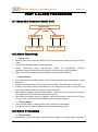
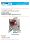
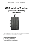
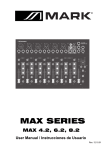
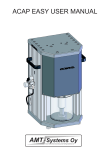
ShenYan Security Center Management - Page 1 - ShenYan Security Center Management User Manual (V5.5) Chengdu Ideal Technology Development Co., Ltd. Chengdu Ideal Technology Development Co., Ltd. http://en.cdlxkj.com ShenYan Security Center Management PART 1 1.1 - Page 2 - OVERVIEW BASIC SETTING ShenYan Security Center Management System includes 5120 Alarm Receiver and Software. Industrial control computer Dual-core CPU above 2.0 Memory over 2G Hard Disk over 250G Sound card above 32 bit Monitor Laser/Inkjet Printer UPS battery Dynamo Generator (≥ 500W) 1.2 MAIN FEATURES Automatically recognition of ADEMCO 4+2, CONTACT ID, and LX6688 protocol Special command and dispatch functions Protocol can be extended or separately modifications Compatible with Contact ID alarm control panel Automatically do periodic monitor of alarm control panels Auto-forwarding of Alarm info Remote Arm/Disarm/Programming Client Info Management System Service charge management and extended prompts Various Database Inquiry: classification, specified, fuzzy Vectorization electronic map (District Map and Defense Zone map) Automatic multimedia Alarm, automatic print, automatic electronic map positioning Alarm processing and prompted of untreated system Database backup and restore Alarm Log Inquiry Ease operator authority management Status Monitoring of alarm receiver Control Panel status management and inquiry 1.3 NOTICE PC in security center is in continuous work status. Industry control PC is recommend to maintain stable system operation; Chengdu Ideal Technology Development Co., Ltd. http://en.cdlxkj.com ShenYan Security Center Management - Page 3 - Make Windows display mode above 1024*768 Auto-hide the status bar Do not attempt to install other software on security center PC Do not dial via dedicated center telephone line PART 2 INSTALLATION 2.1 SY5120 Alarm Receiver SY5120 in CD-ROM style is with LCD display, which can display alarm info, status prompt (PC, Alarm, Transfer, Line, etc.). It can process data from two line at the mean time. Alarm info can be transferred to Superiors/ Subordinates Center, while controlled by center software. SY5120 can do failure prompt of PC, and auto-restore latest 112 events when there‟s PC operation failure. You can also check latest 96 events via UP/DOWN button on SY5120 panel. SY5120 Panel LCD Display Information 1. POWER ON: LCD full screen display and delay. After that, center prompt shows „bEg‟ 2. TIME DISPLAY: display current time while no new events, or events have been processed; display event‟s time while S/N displaying 3. PC FAILURE/RECOVERY: When PC connection failure, center „beeper‟+LCD display „PC‟+‟S/N‟ flashes; After recovery, LCD display „PC‟+‟S/N‟ normally display 4. PSTN LINE FAILURE/RECOVERY: While PSTN line failure, LCD display „Line--01‟ or „Line--02‟. Meanwhile „S/N‟ normally display. 5. ALARM PROCESSING DISPLAY: LCD display details (User#/ Zone#/ Alarm info). „S/N‟ flashing stands for alarm or failure. „S/N‟ normal display means alarm recovery/failure recovery. „Zone‟ is hidden while communication protocol is „4+2‟, meanwhile „Zone NO.‟ displays alarm code. If alarm is not within the code, alarm area will show „Others‟, meanwhile, „Zone‟ is hidden, „Zone NO.‟ displays alarm code. Item „S/N‟ Status Description Flash Alarm or Failure or Other alarm codes in CID protocol Normal Display Alarm Recovery or Failure Recovery or Arm/Disarm or Other recovery in CID protocol SY5120 Panel LCD Display Information 1. POWER: Power working well, light on 2. PC: Serial port or PC working well, light on. Otherwise, light off 3. ALARM: New alarm info, light on; „Stop/Checked‟ or transferred to PC, light off 4. TRANSFER: transferring to superiors/ subordinates center, light on. After transferred, light off 5. LINE: PSTN line failure or unconnected, light flashing; light off while working well or recovered; light flash with ring while there‟s a call; light on while receiving alarm info; light off after info received 6. UP: Check the previous info Chengdu Ideal Technology Development Co., Ltd. http://en.cdlxkj.com ShenYan Security Center Management - Page 4 - 7. STOP/CHECKED: stop sound prompt/relay output/inquiry; check alarm one by one 8. DOWN: Check the next info 9. PSTN wire holder: connecting the PSTN line of alarm receiver 10. Serial port wire holder: connecting the serial port and PC/RS232 port with a cable 11. Output wire holder: the two middle of holder for relay output; two ends for „+/-‟ of 12V 12. Alarm receiver will transfer info to management software on PC, and receiver will display current time after transferred. And LCD backlight on if there‟s PC or communication failure. Meanwhile, receiver will decide the sound out or relay output. Duty person can do „Stop/Check‟ to control „sound out‟ and check alarm info, when PC connection failure. Item POWER PC ALARM TRANSFER LINE Status Description OFF ON OFF ON OFF ON OFF ON OFF FLASH ON Receiver OFF (Power OFF) Receiver ON (Power ON) Serial port connection failure/Software failure PC connected with receiver & Software working well No new alarm info or all alarm info handled New alarm info or other event transferred to superiors/ subordinates center transferring to superiors/ subordinates center PSTN line connecting well PSTN line failure (slow flash) or there‟s new call (fast flash) Receiving alarm info 2.2 SY5120 Network Alarm Receiver Installation Stable & reliable SY5120 is designed as CD-ROM style. Easily to be installed into the PC. And you can also just put it on the desk. SY5120 Installation information as following: Take off screws on CD-ROM mounting deck Install the receiver on the mount deck, and adjust the position, fix with screws (>4) Connect the power plug of CD-ROM with the receiver Connect the receiver serial port with PC‟s via a cable Connect the PSTN line of security center with the receiver Screws on CD-ROM mounting deck CD-ROM mounting deck CD-ROM Industrial PC Chengdu Ideal Technology Development Co., Ltd. http://en.cdlxkj.com ShenYan Security Center Management - Page 5 - 2.3 Center Management Software Installation Software is in the CD in the accessories: Open the CD, and double click „setup.exe‟ Follow the installation guide (installed in Drive:C) Install the Office 2003, to print alarm log and events reports Data back-up to Drice:D or Drive:E 2.4 Notices PC power should be off while installing alarm receiver Install software after alarm receiver been installed Receiver can be powered by PC while connected with the PC. Also can be powered by extra 12V when using on the desk. Receiver is encrypted with the software. Only can work well when input correct software PWD. Otherwise, security center can only be at When need transferred to Superiors/ Subordinates Centers, two PSTN line is recommended. Then line 1 can be set as „new alarm info‟ priority, while line 2 is „transferring‟ priority. When one line got failure, they can be each other‟s back-up. PART 3 Security Center Settings Notice: Adjusting settings will take some influence on alarming receiving. So pls do it bypass the alarming peak period. Only sound out of alarming while doing settings. Don‟t ignore each alarm. 3.1 Run software Click ‘Start’—‘Programs’—‘Security Center’, then Login in. Account of duty person default is „0001‟ (Administrator Account). Default PWD is „123456‟. Choose the suitable server. Notice: Pls change PWD after the setting Duty person includes „System Administrator‟, „Data Entry Person‟, and „Regular Duty Person‟. „System Administrator‟ own the biggest permission. Default duty person is „System Administrator‟. Account & PWD is „0001‟ & „123456‟. Account & PWD input is Case-insensitive. Only correct account & PWD can enter the software. Chengdu Ideal Technology Development Co., Ltd. http://en.cdlxkj.com ShenYan Security Center Management - Page 6 - 3.2 Working Interface Menu Bar Toolbar Working Area Internet Status Bar Main work interface includes „Menu Bar‟ & „Toolbar‟ & „Working Area‟ & „Status Bar‟. MENU BAR: System Control/ Map/ Info Management/ Event Management/ Data Maintain/ Windows Control, etc. management functions. TOOLBAR: common functions (Whole Map, Map View, User File, Control Panel Status, Alarm Info, System Journal, Command & Dispatch, etc.) and other functional buttons (Display/Hid Users/Data Download, etc.) WORKING AREA: display opened windows (Whole Map, User File, Control Panel Status, Alarm Info, System Journal, etc.) STATUS BAR: show status of the security center (Duty person/ Center name/ Num. of timeout users/ Serial port status/Current time/date, etc.) 3.3 Map Installation Info Maps: Aspect ratio should be about 2:1 (>1024*800 resolution). The „bmp‟ or „jpg‟ format is recommended for the map. And saved at „C:\Program files\Security Center‟ file. Installation: click the „Maps‟ option button. And then start installation guide. Click „choose‟ to use your maps. Chengdu Ideal Technology Development Co., Ltd. http://en.cdlxkj.com ShenYan Security Center Management - Page 7 - 3.4 User Files Add a new user Click the [User Management], and choose the [Add a new user] or open [User Files]. Basic Info: [Edit] button to enter the info edition Input the basic info: User NO./ Type/ Name/ Address/ ATTN., etc. [Remarks] to show notices about this user User Location: click [user location], then switch to „Map Browsing‟. Locate the user at its ADDS. Then back to the previous page Remarks: The center group NO. is automatically generated. Report Settings: [Edit] button to enter the report settings Basic info for report: Police ATTN./ Police TEL/Police Station/ Area NO. (Conducive for center command and dispatch) Test interval: *hours, should be one hour more than control panel‟s test interval Periodic arm time: best to be as per user‟s request. Center will have prompt if no arm while the set time Treatment programs: remarks for each users Control Panel Info: [Edit] button to enter the control panel‟s settings Model NO. of the control panel: for remote programming function Caller ID check: enter correct TEL. If caller ID check feature is ON, center will do it automatically while called. Then do prompt to duty operator Remote Arm/Disarm Permission: Yes/No for regular duty operator Detectors Overview: Module NO., Model NO. of the detectors, Defense Zone Position, Remarks Installation: Date/Time, Location, Installer, etc. Defense Zone Settings: [Edit] button to enter the defense zone‟s settings Choose the module, then [Add], [Edit] to add new zones/edit zones. After edition, you can do [Save] or [Delete] to save settings or delete zones Input defense zone NO., zone type, detector location, detector model NO., ATTN., TEL., etc. Transferring: input transferring NO., and do transferring type at the right buttons Zone Layout Creat a zone layout diagram, then save at „USER‟ folder Click the „Zones Diagram‟ to choose the right file. Then [open], windows will show the zone layout Move the cursor to the red triangle icon, then locate the zones. Cursor Num. should be equal to zone Num. (not relative to detector Num.) Chengdu Ideal Technology Development Co., Ltd. http://en.cdlxkj.com ShenYan Security Center Management - Page 8 - Control Panel Status: Alarm log is automatically updated while control panel sending alarms. Cannot be artificially modified Monitoring Settings: Video monitoring & alarm integrated: choose “√” for Yes. Video prompt will be with alarm info. Duty operator can do video monitoring then. Video recording: choose “√” for Yes. Then center can do video recording while alarming. Automatic horizontal mirroring: To swap horizontal orientation automatically while alarming. Automatic vertical mirroring: To swap vertical orientation automatically while alarming. Automatic voice monitoring state: enable voice monitoring on-site while alarming. Automatic propaganda state: shout to the site while alarming. Video Pop-out while disarming: set the time segment, then pop-out video while disarming. Camera IP: automatically obtain the IP address Edit User File Choose the user from [User Listing], then double click or right click [Edit User] Delete User Appoint to the user, right click then choose the [Delete User]. Then confirm the deletion Service Charge Management Open [User Listing] or [Service Charge Management], then choose the [Payment]. Or right click to choose [Payment]. Input the charge Sum., Ticket NO., Service Deadline. Since cannot revise the service charge settings, so do careful check before saving. Terms Query From field ‘1’ to ‘4’, input the terms: [Like]: The field includes the query [=]: The field is equal to the query [>]: The field is higher than the query [>=]: The field is higher or equal to the query [<]:The field is less than the query [<=]: The field is less or equal to the query [<>]: The field is not equal to the query Input the query at the right part Sequence Field: Choose the 1st and 2nd field, and then do „little-endian‟ or „big-endian‟ Click [Query], software system will do query based on the set terms. Then software will display the results. [Simple Query] or [Term Query] optional: can do simple query as per alarm time/user NO./alarm description Notice: Query mode has automatic memory function. System will do query based on last mode. Chengdu Ideal Technology Development Co., Ltd. http://en.cdlxkj.com ShenYan Security Center Management - Page 9 - Printer Right click to choose „Printer‟ at the „User Listing‟, „Alarm Log Query‟, „Service Charges Management‟ windows. Blue appoint to add the field. White appoint to add all fields. Left appoint to cancel output. Click [Printer], to pop-out file window. Input the file name and then open the file. Excel file will be generated and displayed. Edit the Excel file and do printing. Here, pls use ordinary laser or inkjet printer. Notices User NO. can be 4 digi. (System will generate the six NO. with 2 front 0), or 6 digi. When create new or edit the User NO., pls confirm it‟s unique. And the control panel should be programmed with the same user NO. There is no need setting modify at the „Control Panel Status‟. Defense zone diagram should be saved as „bmp/jpg‟ format, and under „C:\Program files\Security Center\user\‟. Center will call the „Transferring Num.‟ in „Report Settings‟ while alarming. And transfer the alarm info as per ordered to another center or linked alarm center. When there are transferring Num. in both „Report settings‟ and „Zone settings‟. Center will communicate with Num. in „Zone settings‟, then „Report settings‟. The charge Sum. and ticket NO. should be confirmed before saving. Revising and editing is not available after saved. 3.5 Serial Port Settings Click [System Control], then [Serial Port Settings]: Choose the serial port NO. (4 ports are supported) Set the „online check time‟/‟Remote Programming‟/‟Alarm Transferring‟/‟Monitoring‟, etc. Serial port #1 and #2 are generally used. Interval should be over 60 seconds. 100 seconds is recommended. Remarks: Do serial port failure detection only when ‘Monitoring’ is ON. Some features got default. There is no need to modify. Save current settings to enter another serial port setting. Or you can close the setting windows. [Time Calibration] to make sure the alarm receive is at the same time with the PC installed with security center software. And it‟s for all opened serial ports. Serial Port ON/OFF: In [System Control], port with “√” is ON. Otherwise it‟s off. Click the serial port, you can choose to open/close the serial ports. In the drop-down menu, port is gray is unavailable. In the status bar, 8 port icon stands for 8 serial ports. RedBlue/Green icon stands for ON/Using/OFF three status. Chengdu Ideal Technology Development Co., Ltd. http://en.cdlxkj.com ShenYan Security Center Management - Page 10 - 3.6 System Settings Click [System Control], then [System Settings]: [Security Center Name] stands for the name of center. And will be displayed at the status bar. [Display User Group] will decide whether display the user group Num. in the [user listing] or [alarm log]. [Display Alarm Log]: displayed info at the „Unprocessed events‟ in the alarm log windows. [ALL] stands for all alarm info should be displayed, including alarm/arm/disarm/failures, etc.; [Partial] stands for only display alarm info; [Solved] stands for there is no info left. Input value*seconds in the „Alarm Log‟ and „Alarm Prompt‟ windows. The former stands for the display time of „Alarming‟ windows. And the latter is for alarm duration of the alarming. Center checksum: set the 6 digi. PWD (control panel should do the same value programming) Limited off-line time: in the set time period, center will not do prompt. When take off the „√‟, only do prompt while armed. 3.7 Protocol Settings Click [System Control], then [Protocol Settings]: In the drop-down menu on the left, you can choose the protocol (Contact ID, 4+2, LX6688 etc.) Click [Add] or [Edit] button to enter the „protocol edition‟ windows. Can also double click the protocol to enter the edition. Edit the Alarm Code/Alarm Description/ Auxiliary Information. At the [Sound] option, “√” is for sound alarm. Meanwhile, center will do prompt while receiving the sound alarm. Otherwise, center only store the alarm info. And no prompt for duty operators. At the [Sound Files], you can modify the sound prompt among the installed sounds file. Also you can add customized sound under „C:Program files\Security Center\sound\‟ folder. The limitation if 5 seconds long. Color Prompt Settings: „Foreground color‟ if for text of alarm log; „Background color‟ is for alarm info background. You can modify several groups, to make prompt efficiently. Remarks: when using 4+2 protocol, modify the alarm code if alarm prompt is different from the control panel‟s alarm category. 3.8 Printing Mode & Auto-printing Click [System Control], then [Mode Settings]: Content of Mode #1 is overall. It can be used as processing notice sheet. Content of Mode #2 is simple. It can be used for file management. [Test] can preview the content & mode. Chengdu Ideal Technology Development Co., Ltd. http://en.cdlxkj.com ShenYan Security Center Management - Page 11 - When [Auto-printing] is on. Center will print the alarm info while receiving the alarm. 3.9 Duty Operator Management Add a new duty operator Click [File Management], then choose the [Add]; or click the [Duty Operator List] to [Add]: Input the duty operator name/user name/PWD. Set the authority of the operators: regular operators/data operators/administrator Modify the PWD Click [File Management]], then [PWD Settings]: all operators can do PWD revising. However, can do their selves‟ only. Duty Operator List Click [File Management]], modify/delete/add operators. then [Duty Operator List]: Only administrator can Notice Administrator got the Maximum permissions. Default administrator is „0001/PWD123456‟. It can add/modify/delete operators. And system should have at least one administrator. If there‟s no operator, software cannot be started. Then pls contact your software provider for technical support. Authority (Only display the difference) FEATURES Protocol Settings Serial Port Settings Receiving Code System Settings Alarm Test Auto-Printing Mode Selection Serial Port ON/OFF Map Installation Add Operators Operators List Service Charge Management Back-up Alarm Log Back-up System Events Add a new user Back-up User File Recovery User File Printing YES YES YES YES YES YES YES YES YES YES YES DATA OPERATOR NO NO NO NO YES YES YES YES NO NO NO REGULAR OPERATOR NO NO NO NO NO NO NO NO NO NO NO YES YES NO YES YES NO YES YES NO YES YES YES YES YES YES YES YES NO NO NO NO ADMINISTRATOR Chengdu Ideal Technology Development Co., Ltd. http://en.cdlxkj.com ShenYan Security Center Management - Page 12 - PART 4 ALARM PROCESSING 4.1 Open the Receiver Serial Port Security Center ALARM Receiver #1 Line #1 Line #2 Receiver #2 Line #3 Line #4 4.2 Alarm Receiving Alarm Code Security center can receive the alarm info from control panels, while receiver‟s serial port is ON. Contact ID/4+2/FSK/LX6688 protocol supported. Center TEL/Control panel NO./Protocol should be programmed correctly. Alarm/Arm/Disarm should be the same with the code settings in „Protocol Edition‟. Center will do prompt/map guide/onsite alarm/auto-printing automatically. Alarm Prompt The bottom right will display „Alarm‟ prompt. Red and black flash alternately to remind operators. If there are multiple alarm events queued for processing , the latest alarm is at the top. If there is new alarm while center software is in the map display, current user tag is in red and yellow. While, queued user tag is in green and purple. When alarm log display choose „Partial display‟, center will only do prompt of new alarm info. Meanwhile, center will automatically solve the info. When alarm log display choose „All display‟, center will prompt all alarm info. And if set it as „Auto-solve‟, all info will be automatically solved by center software. Printing Output There are two modes of alarm printing output: Artificial or Automatically. Only print the sound alarm info based on automatically printing mode. 4.3 Alarm Processing Alarm Prompt Sound alarm: system will make automatic decision based on „Protocol Edition‟ settings. If Chengdu Ideal Technology Development Co., Ltd. http://en.cdlxkj.com ShenYan Security Center Management - Page 13 - it‟s not sound alarm, system will only store the alarm info. For sound alarm event, system will do sound and window prompt. Alarm processing notice sheet includes „User info‟, „Zone info‟, „Alarm info‟, „Alarm judgement‟. You can check alarm event details via „Alarm Query‟. There are two bars in [Alarm Query]: solved alarm and queued alarm. At the queued alarm, left click the mouse to enter the procession notice window. Right click to enter the user file query. The queued alarm window can only display 5 events. And can check Max. 200 events. Events over 200 will be automatically solved. Term query/printer output/data update are only for solved events. Not available for queued alarm events. Alarm Processing Notice Click the [Alarm Processing] button while alarming & flashing windows, then can enter the notice window. Check user file details for arrange proper solution for alarm processing. Alarm processing results: processor/onsite check results/solution/result summary ,etc. Command & Dispatch As per different processing solutions, to determine whether there‟s dispatch. If needed, click the [Processing Dispatch]. System will remind the nearest police Address/TEL./ATTN. After command & dispatch, system will back to [Processing Notice] windows. You can do below operation at [Command & Dispatch List]: Area choosing: choose the area for different users. Protocol choosing: choose the protocol and then saved for the next dispatch. Police TEL: right click to enter the [Command & Dispatch file], to add/delete a TEL. The modified TEL is only available for „command & dispatch‟. Area dispatch: command all police station in the area. Overall dispatch: command all police station belong to the center Alarm Processing Results Below is result pattern: „Real Intrusion‟----Confirmed intrusion „System False Alarm‟---- Operational errors, False triggering detector „Human False Positives‟---- Human errors , False triggering „System Events‟----Operation Failure „Alarm Test‟----Test of the alarm system ( no need command & dispatch) „Unknown Events‟----cannot be checked Chengdu Ideal Technology Development Co., Ltd. http://en.cdlxkj.com