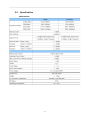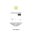
1
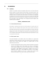
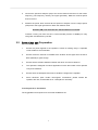
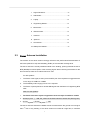
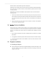
MR Ultra 33dB Repeater User Manual Preface This User Manual provides installation, configuration, operation and maintenance guidance of the repeater. Specifications are also provided at the end of this User Manual in order to help users better understand the repeater. Please read this user’s manual thoroughly and follow the instructions outlined in this manual to ensure a long life span and a trouble-free repeater unit. Warranty Lightning protection must be done for all outdoor antennas. Damage to power modules, as a result of lightning is not covered by the warranty. Switching on the AC or DC power prior to connection of antenna cables is considered as an incorrect installation process and therefore faults arising thereafter are also not covered under the warranty. This entire manual should be read and understood before operating or maintaining the repeater system. We assume no liability for customer's failure to comply with the precautions mentioned. This warranty will not cover such failures to comply. Safety Information Do not operate equipment in an explosive environment. Appropriate AC or DC power needs to be supplied to the repeater. To avoid power supply spark, please perform the grounding connection of the equipment. In order to avoid equipment damage or human injury by lightning, static electricity and other phenomenon of leakage electricity, Baselink suggest all products must do the electric-discharge of the electrical grounding in setup process. Incorrect power settings can damage the repeater and may cause electrical related injury to the user. Acknowledgment Thank you for purchasing the Baselink repeater. Strict quality control system procedures are implemented to ensure you a high quality product; with numerous cellular operators acknowledging the product to be a high performance, low interference, transparent and simple to operate and maintain. This document is written for Baselink and customer service personnel, who install, configure and commission the repeater system in a cellular network. 1 Contents 1. INTRODUCTION.......................................................................................................3 1.1 Broad Band Repeaters ........................................................................................................ 3 1.2 General Installation Layout................................................................................................ 3 1.3 Advantages ........................................................................................................................... 4 2. INSTALLATION........................................................................................................5 2.1 Isolation ................................................................................................................................ 5 2.1.1 Self-Oscillation Resistance ........................................................................................................................5 2.1.2 The Isolation Value ...................................................................................................................................5 2.2 Precautions and Preparation ............................................................................................ 6 2.3 Donor Antenna Installation ............................................................................................... 7 2.4 Service Antenna Installation ............................................................................................. 8 2.5 Repeater Installation ........................................................................................................... 8 2.5.1 Installing the Repeater...............................................................................................................................8 3. COMMISSIONING ..................................................................................................10 3.1 Downlink Output Power ................................................................................................. 10 3.2 Repeater Configuration..................................................................................................... 10 3.2.1 Start-up the Repeater ...............................................................................................................................10 3.2.2 Repeater Settings......................................................................................................................................11 4. MAINTENANCE......................................................................................................14 4.1 Status, Alarms possible Solutions..................................................................................... 14 4.2 Troubleshooting ................................................................................................................. 16 4.3 Replacement ....................................................................................................................... 17 5. APPENDIX ..............................................................................................................18 5.1 Abbreviations ..................................................................................................................... 18 5.2 Specification ....................................................................................................................... 19 2 1. Introduction 1.1 Broad Band Repeaters The BU33 Series Repeater is compact in size and light in weight. Hence, the installation of the BU33 Series Repeater is easy, simply just plug and play. With the control panel in front of the repeater, the repeater status can be known during installation. Figure Error! Reference source not found. LED Indicators 1.2 General Installation Layout Figure 1 Profile For indoor application, a typical installation layout of the Broad Band Repeater is shown in Figure 1. The Yagi antenna is used as the donor antenna, and is connected to the repeater. Omni and panel antennas are being used as the service antennas. The donor antenna is placed outside of the building, while the repeater is placed inside the 3 building to extend radio coverage to the dead zones. 1.3 Advantages Fast & easy Installation The installation of a repeater is easy and simple. With its plug and play design, installation simplicity, and operational user friendliness, these features appeal greatly to many operators for the purpose of indoor coverage or for temporary coverage during network optimization. Smart Function Compare to the worldwide repeater brand, the BU33 series has a smart function called which can be activated via the front panel. This smart function can prevent UL interference and self-oscillation caused by insufficient isolation between donor and service antennas, and also setup parameters and keep optimal condition automatically; the only thing for users is just activating this function by front panel. Notify that the users can’t adjust by manual setting when smart function is initiated. Auto Level Control The 20dB ALC is used to maintain steady output power even when the donor source signal fluctuates. Also when the ALC is activated, the ISOLATION LED indicator would be lighted in orange, which means the Isolation may not be enough. It also prevents UL interference and self-oscillation from insufficient isolation between donor and service antennas. 4 2. Installation 2.1 Isolation Isolation is an important concept for the repeater system, and it is one of the factors that affect the location of the donor antenna and the location of the service antenna. In the repeater system, the isolation must be enough, which means the donor antenna cannot be installed too close to the repeater. But what is isolation? The isolation is the propagation loss between the donor antenna and the service antenna which needs to be at least 15dB higher than the gain value of the repeater. Non-compliance to this criterion would result in poor signal quality or poor signal strength in the coverage area and the amplifier of the repeater may also be damaged. Isolation Repeater Gain + 15 dB 2.1.1 Self-Oscillation Resistance Self-oscillation is a phenomenon that would occur when the isolation for the repeater system is not enough. In other words, insufficient isolation between donor and service antennas would result in self-oscillation. Which means part of the signal that is being amplified by the repeater radiates back towards the donor antenna and got picked up by the donor antenna and went through the repeater amplification process again. Severe oscillation issue would result in poor signal quality and at times it can even damage the repeater amplifiers. Self-oscillation will deteriorate the signals inside the coverage area and interfere towards the BTS. 2.1.2 The Isolation Value The precise estimation of the isolation value can be obtained via a physical test measurement. This test measurement is done at the actual environment where the donor antenna and the service antenna are installed for a repeater system. The test measurement procedures are 1. Connect the signal generator (SG) to the donor antenna and transmit a signal with a frequency (For GSM900, uplink is 890~915MHz and downlink is 935~960MHz. Choose frequency 920MHz to do the test. For DCS1800, uplink is 1710~1785MHz and downlink is 1805~1880MHz. Choose frequency 1795MHz to do the test. For WCDMA2100, system uplink is 1920~1980MHz and downlink is 2110~2170MHz. Choose frequency 1995MHz to do the test. In simple words, choose the idle frequency of the system to do the test) of certain power level from the SG. 5 2. Connect the spectrum analyzer (SA) to the service antenna and scan for the known frequency (The frequency used by the signal generator). Mark the received power level on the SA. 3. Subtract the power level received at the spectrum analyzer from the output power (OP) level of the signal generator to obtain the isolation value. Isolation (dB) = OP from the SG – Received Power on the SA Transmit a strong OP from the SG is recommended (excess of 20dBm) for easy recognition and detection by the SA. 2.2 Precautions and Preparation 1. Ensure the power applied to the repeater is within its working range. A separate circuit breaker is recommended. 2. Ensure the donor antenna is installed at the location where signal from the donor BTS (Node B) is good enough. 3. Ensure there’s sufficient isolation between the donor and service antenna. 4. The repeater is designed for indoor application. Ensure the location of the repeater is dry and ventilative. 5. Ensure there are adequate resources to handle the weight of the repeater. 6. Some electronic parts contain carcinogenic constituents, please handle the repeater with care, and discard the in a safe place if necessary. Tools Required for Installation The suggested tools required for a successful installation are: 6 1. Signal Generator......................................................x1 2. Site Master...............................................................x1 3. Laptop......................................................................x1 4. Engineering Mobile..................................................x1 5. Multi-meter...............................................................x1 6. Electrical Drill...........................................................x1 7. Hammer...................................................................x1 8. Spanner...................................................................x1 9. Screwdriver..............................................................x1 10. Waterproof Sealant..................................................x1 2.3 Donor Antenna Installation The location of the donor antenna strongly influences the performance/characteristics of the RxLev (RSCP for 3G) and RxQuality (Ec/No) of the intended coverage area. The donor antenna is usually installed outside of the building, pointing towards the donor BTS (NodeB) for best reception of the receiving signal. When choosing the location for the donor antenna, there are 3 criteria need to be met: For 2G Systems 1. The Rxlev of the signal, at the input to the BTS port of the repeater is suggested to be in the range of -55dBm to -70dBm 2. The RxQuality index ranging from 0 to 2 is required. 3. The Rxlev of primary BCCH is at least 6dB higher than the BCCH of neighboring BTS sites. Note: For 3G Systems 1. The RSCP of the donor signal is suggested to be in the range of -60dBm to -70dBm. 2. (Ec/No)AS_CPICH ≧ -7dB; AS_CPICH is the Pilot Channel in Active Set (Serving Cell) 3. (Ec/No)AS_CPICH – (Ec/No)MS_CPICH ≧ 6dB The donor antenna should be installed at least 3 meters above the ground but not higher th than 7 floor of any building. If the donor antenna is located at a high floor, it would be 7 difficult to obtain a dominant BTS signal from nearby BTS. A lightning rod is necessary when the donor antenna is located at a relative high position. On the other hand, an arrestor could be connected between repeater and donor antenna for better protection. Waterproofing of the antenna installation is also important, and it can be done with the following process: 1. Use the donor antenna cable to form a half loop at the point of entry into the house so that rain water would drop off instead of flowing inside along the cable, and also also form a half loop before the antenna cable connects to the repeater as the waterproof measure. 2. Secure the cable entry point. Seal the donor antenna’s connector and repeater’s connector with a waterproof sealant. 2.4 Service Antenna Installation Find the right spot to install the service antenna so the required coverage can be fully covered by the repeater is one of the most important concepts that needs to be considered. However, the following three points should be considered while installing the service antenna. 1. Do not install the repeater near metal or obstacles that may influence its coverage performance. 2. It is suggested to install the repeater at least 2m above the floor for the best coverage. 3. The service antenna should not be installed to close to the donor antenna to avoid issues with isolation. 2.5 Repeater Installation 2.5.1 Installing the Repeater Use the hanger that comes with the repeater package, and place the hanger on the wall where repeater is going to be installed, use the hole on the hanger to secure the hanger on to the wall. 8 Figure 2 Mark the holes Use the back of the repeater to hang on the Hanger and complete the installation. Connect the donor antenna cable to the BTS port of the repeater and the service antenna cable to the MS port of the repeater. A lightening arrestor needs to be connected to the repeaters’ BTS port when the donor antenna is installed in a high position. Grounding is essential for the arrestor to work. Plug the power cable to the repeater first before plugging in the power cable to the mains socket. Use the power cable that comes with the package. 9 3. Commissioning This chapter outlines the process to optimize the performance of the repeater. The gain setting, isolation concept, and downlink output power. 3.1 Downlink Output Power The downlink output power of the repeater mainly depends on the input signal power and the repeater gain. The gain is the amplifying indicator for both uplink and downlink in the repeater, and it can be adjusted. Hence, the output power of the repeater can be estimated. Signal Input Power + DL Gain = DL Output Power For any given input signal power, its corresponding output is increased by the gain of the repeater. To ensure the maximum output power, the following condition should be met. DL Gain = Min [(DL Output Power – Input Power), Max. DL Gain] If the input signal amplified by the gain set exceeds the rated set output limit, the ALC (Automatic Level Control) will be triggered. The ALC ensures that the maximum output power of repeater is maintained at a certain point and does not overdrive the repeaters amplification circuit. 3.2 Repeater Configuration The BU33 series repeaters are designed with plug and play ability. The configuration for these repeaters is not necessary, simply just switch the Smart function on, and the repeater would auto adjust its gains according to the environment condition. 3.2.1 Start-up the Repeater Note: It is suggested that only when isolation is 15dB higher than repeater’s gain then the repeater can be switched on. Make sure power supply cable is connected to the repeater properly, and the voltage is within repeater’s voltage working range: 110/220V ± 20% Plug the power cord into the proper socket. Once the repeater is on, it requires several seconds for initialization. 10 When Repeater is close to the BTS, hence there is a high input power at the donor antenna. Even with the smart ability of the auto gain adjustment, it is still recommended to add an RF attenuator at repeater’s BTS port to avoid interference to the BTS. 3.2.2 Repeater Settings After switching on the repeater, the repeater would automatically adjust both uplink and downlink gain value based on the repeater installation environment if the smart function is turned on. The repeater can also be adjusted manually via the front control panel. Figure 3 Front panel of the repeater B uttons Functions The functions of the buttons on the front panel are listed in the table below. Button Function Explanations Press the button to select between either uplink (UL) Select UL or or downlink (DL) for the band, the indicator DL represents either UL or DL you are at and intending to operate. 11 Press the button to confirm the selection, press again and the LED keeps blinking, means now in the mode of setting. Store the Changes After setting the attenuation, press the store button again and the value would be stored into the repeater, and the LED would stop blinking and display the value, the process is then complete. Increase or decrease the Gain Activate or Deactivate the Smart function Press the button increase or decrease the attenuation by 1dB/step, and the LED monitor would display the current gain value; press the store button to complete the settings. Press the button to activate the smart function,the smart indicator would be lighted, and press store button to take effect. T he LED monitor The LED monitor is composed by 2 digits which displays the current gain value, when LED is blinking, the system is in the mode of setting the attenuation. When LED shows 88 and keeps blinking, the system is in initializing status (it takes 12 seconds to complete the initialization) 12 T he Indicators There are four kinds of indicators on the front panel, and they are listed Indicator Status Power Indicates that the power supply is normal. Indicator UL/DL Indicator This UL/DL Indicator indicates either the LED monitor is displaying the UL band or the DL band. indicates the Smart Function is OFF Smart Function Indicator indicates the Smart Function is ON When the indicator is green, it is in normal status. Alarm Indicator When the indicator is red, it means the output power is out of AGC range. An Example of Setting (To set attenuation for the uplink) Step 1:Press SELECT till the indicator stops at uplink. Step 2:Press STORE and LED monitor starts blinking. Step 3:Press“+”, “-”to an intended gain value. Step 4:Press STORE to set the value and the LED stop blinking and showing the gain value at the moment, the process is done. 13 4. Maintenance 4.1 Status, Alarms possible Solutions The following table lists the meaning of the Alarm that is on the front panel and the possible solution correct it ALARM LED Alarm -1 Green Alarm -2 Green Cause AGC active Solution Work normally 1. Decrease gain value Alarm -1 Red Alarm -2 Red 2. Increase the distance between donor and service AGC Warning antenna. If 1 and 2 can’t work, please return to seller for repairing. The following table lists the alarms may appear on monitor screen when using OMT tool, please process the alarm according to the solution indication. Alarm Cause 1. High input level at the BTS port of the repeater, AGC is active and DL AGC ALARM more than 30dB attenuation has been applied. 2. An isolation condition may also have occurred. Solution 1. Decrease the gain by adjusting the manual attenuation accordingly to clear the alarm. 2. Increase the separation distance of the donor and service antenna. 1. Check whether the input DC power is stable. If the DC is not stable, an UPS PA Failure The power of PA is not stable with square wave is recommended. 2. Restart this repeater. If input DC power is correct and alarm still 14 exists, return the unit to place of purchase for repair. 1. Check whether the input AC power is stable, it should be within 110/220V ± 20%. If the Power Module Alarm 1. Input AC power is not stable. 2. Repeater’s power supply module has been damaged AC is not stable, an UPS with square wave is recommended. 2. In the condition input AC power is correct and alarm still exists, return the unit to place of purchase for repair. 1. Execute the Default Setting through OMS. The PLL circuit cannot lock onto the PLL Unlock programmed frequencies. The operating frequencies of repeater may have been accidentally shifted from the OMT software. Refer to OMT User’s Manual for more detail. 2. If the alarm cannot be solved, it means repeater has been damaged. Please return the unit to place of purchase for repair. 15 4.2 Troubleshooting This table offers the fundamental guidelines for troubleshooting advice for the BU33 series. Before sending the repeater back to the factory for service, please check the troubleshooting measures listed below first. Status Possible Reason Solution 1. Check if the power cord is plugged into the repeater and No amplification after 1. No AC power. repeater installed. 2. Donor Signal is poor the socket properly. 2. Ensure signal signal quality strength at the and donor antenna is good enough. 1. Donor signal strength decreased. 2. The quality of feeder cable system decreased Coverage decreased after certain period. 1. Check the signal strength at donor antenna. Re-locate the Donor Antenna to solve problem. due to oxidization 2. Check the VSWR of the feeder especially in harsh cable system to find out the conditions, or cable faulty point and then replace it damage by mice or insects. 3. Reconsider the position of antennas and the layout of 3. Change of indoor cables if such change occurs. structure or upholstery. 1. Self-oscillation occurred severely. ISOLATION Bad Rx Quality inside LED may be lighted in the coverage area red. 1. Check the isolation between donor and service antenna. 2. Adjust the donor antenna 2. Poor Rx Quality from donor source direction or relocate the donor antenna. 1. Check the isolation between Call drop frequently 1. Self-oscillation occurred. donor and service antenna. 2. Signal handover Turn on the Intelligent Mode frequently. 3. Donor BTS problem 2. Make sure the Rx Lev for primary BCCH≧than 1st neighbor BCCH 6dB 16 3. Consult the operator’s RF engineer. 4.3 Replacement The procedures of repeater replacement are: Disconnect the power cord. Disconnect the donor antenna and the service antenna cables. Lift the repeater off the wall If another repeater is not replaced immediately, protect the open-ended cables due to water hazard. 17 5. Appendix 5.1 Abbreviations AGC Automatic Gain Control BCCH Broadcast Control Channel BTS Base Transceiver Station DL Downlink Ec/No Signal Quality for 3G E-GSM Extended GSM GSM Global System for Mobile communication LED Light Emitting Diode LNA Low noise Amplifier MS Mobile Station Min Minimum OMT Operation & Maintenance Terminal OP Output power PA Power Amplifier PLL Phase Locked Loop RF Radio Frequency RSCP Signal Strength for 3G RSSI Receive Signal Strength Indication RxQ Receive signal Quality for 2G RxLev Receive signal Level for 2G SA Spectrum Analyzer SG Signal Generator SIM Subscriber Identity Module TEMP Temperature UL Uplink VSWR Voltage Standard Wave Ratio 18 5.2 Specification BU33 Series 19