1
Downloaded by
RadioAmateur.EU
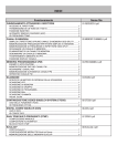
CONTENTS
Operation
OPERATING THROUGH REPEATERS
File name
01-REPEATER-E.pdf
Repeater Access............................................................................................1
Transmitting a 1750 Hz Tone.......................................................................2
REVERSE FUNCTION...........................................................................................3
Automatic Simplex Checker (ASC)............................................................3
Tone Frequency ID.........................................................................................3
MEMORY CHANNELS
02-MEMORY CHANNEL-E.pdf
SIMPLEX & REPEATER OR ODD-SPLIT MEMORY CHANNEL?........................1
Storing Simplex and Standard Repeater Frequencies..................1
Storing Odd-Split Repeater Frequencies...........................................2
Recalling a Memory Channel....................................................................2
Clearing a Memory Channel......................................................................2
Naming a Memory Channel..........................................................................3
Memory-TO-VFO Transfer............................................................................3
Channel Display Function..........................................................................3
PROGRAMMABLE MEMORY (PM)
03-PM CHANNEL-E.pdf
Application Examples...................................................................................1
Storing Data in PM Channels.....................................................................2
Recalling PM Channels................................................................................2
Auto PM Channel store...............................................................................2
PM Channel Reset...........................................................................................2
SCAN
04-SCAN-E.pdf
SELECTING a SCAN RESUME METHOD............................................................1
VFO SCAN.............................................................................................................1
MEMORY SCAN....................................................................................................2
GROUP SCAN.......................................................................................................2
PROGRAM SCAN..................................................................................................3
MHz SCAN.............................................................................................................3
CALL SCAN...........................................................................................................3
VISUAL SCAN........................................................................................................4
CONTINUOUS TONE CODED SQUELCH SYSTEM (CTCSS)
05-CTCSS-E.pdf
USING CTCSS.......................................................................................................1
CTCSS FREQUENCY ID.......................................................................................2
DIGITAL CODED SQUELCH (DCS)
06-DCS-E.pdf
USING DCS...........................................................................................................1
DCS CODE ID........................................................................................................1
DUAL TONE MULTI-FREQUENCY (DTMF)
07-DTMF-E.pdf
Manual Dialing.................................................................................................1
Automatic Dialer............................................................................................1
DTMF Key Lock..................................................................................................2
EchoLink®
What is EchoLink?...........................................................................................1
Setting Up EchoLink Sysop MODE.............................................................1
Storing EchoLink memory..........................................................................2
08-EchoLink-E.pdf
Operation
OTHER OPERATIONS
File name
09-OTHER OPERATIONS-E.pdf
POWER ON MESSAGE.........................................................................................1
DISPLAY ILLUMINATION......................................................................................1
Key Lock.............................................................................................................1
Key Beep..............................................................................................................2
External Speaker Configuration...........................................................2
Programmable VFO........................................................................................2
Changing the Frequency Step Size.........................................................3
Programmable Function Keys..................................................................3
Frequency Direct Entry.............................................................................3
AUTOMATIC POWER OFF (APO)........................................................................4
SWITCHING FM/AM MODE..................................................................................4
Advanced Intercept Point (AIP).................................................................4
S-Meter Squelch.............................................................................................4
SPEAKER MUTE...................................................................................................5
Beat Shift...........................................................................................................5
Selecting an Output Power.......................................................................5
TIME-OUT TIMER (TOT).......................................................................................5
Masking a Band................................................................................................5
Display Partition Bar....................................................................................6
Power On Password.....................................................................................6
PACKET OPERATION
PACKET MODE.....................................................................................................1
Data Band...........................................................................................................2
COM PORT Speed...............................................................................................2
Using EXTERNAL TNC........................................................................................2
TNC COMMANDS LIST.........................................................................................3
10-PACKET-E.pdf
Operation
APRS ®
File name
11-APRS-E.pdf
CONNECTING WITH A GPS RECEIVER OR WEATHER STATION....................2
ADJUSTING THE INTERNAL CLOCK...................................................................2
RECEIVING APRS DATA......................................................................................3
ACCESSING RECEIVED APRS DATA.................................................................3
Display Example..............................................................................................4
SORT FUNCTION..................................................................................................5
FILTER FUNCTION...............................................................................................5
RECEIVING A MESSAGE.....................................................................................6
ENTERING A MESSAGE.......................................................................................6
ACCESSING RECEIVED APRS MESSAGES.......................................................7
TRANSMITTING A MESSAGE..............................................................................7
BASIC SETTING....................................................................................................8
SETTING INTERNAL TNC.....................................................................................8
SETTING GPS PORT............................................................................................8
SETTING WAY POINT...........................................................................................9
PC PORT ON/OFF.................................................................................................9
PROGRAMMING POSITION DATA.......................................................................9
SETTING BEACON INFORMATION.....................................................................9
SELECTING A POSITION COMMENT................................................................10
STORING STATUS TEXT....................................................................................10
SETTING PACKET FILTER.................................................................................10
SELECTING YOUR STATION ICON...................................................................11
SETTING BEACON TX ALGORITHM..................................................................11
PROGRAMMING A PACKET PATH....................................................................12
NETWORK...........................................................................................................13
VOICE ALERT......................................................................................................13
WEATHER STATION DATA OUTPUT................................................................13
SETTING AS A DIGIPEATER..............................................................................14
STORING USER PHRASES................................................................................14
STORING AUTO MESSAGE REPLY..................................................................15
PROGRAMMING A message GROUP CODE..................................................15
SETTING SOUND................................................................................................15
SETTING INTERRUPT DISPLAY........................................................................16
SELECTING A DISPLAY UNIT (1).......................................................................16
SELECTING A DISPLAY UNIT (2).......................................................................16
SELECTING A NAVITRA GROUP.......................................................................16
STORING NAVITRA MESSAGE..........................................................................16
PACKET MONITOR DISPLAY.............................................................................17
DX PACKETCLUSTERS MONITOR....................................................................17
TROUBLESHOOTING.........................................................................................18
TRANSCEIVER RESET
12-RESET-E.pdf
Key Operation..................................................................................................1
Menu Mode.........................................................................................................1
VGS-1 (OPTIONAL) OPERATION
VOICE ANNOUNCEMENTS..................................................................................1
VOICE RECORDER...............................................................................................2
13-VGS-E.pdf
Operation
CROSS-BAND/ LOCKED-BAND OPERATION (K TYPE MODELS ONLY)
Repeater operation mode..........................................................................1
Repeater TX Hold...........................................................................................1
Repeater ID TX..................................................................................................1
WIRELESS OPERATION (K TYPE MODELS ONLY)
File name
14-CROSS BAND
(K TYPE)-E.pdf
15-WIRELESS (K TYPE)-E.pdf
REPARATION........................................................................................................1
CONTROL OPERATION........................................................................................1
WEATHER ALERT (K TYPE MODELS ONLY)
Weather Alert ON/ OFF.................................................................................1
SKY COMMAND II (K TYPE MODELS ONLY)
CONNECTING THE TRANSPORTER WITH THE HF TRANSCEIVER................1
PREPARATION FLOW..........................................................................................2
PROGRAMMING CALL SIGNS.............................................................................2
PROGRAMMING A TONE FREQUENCY.............................................................3
CONTROL OPERATION........................................................................................3
16-WEATHER ALERT
(K TYPE)-E.pdf
17-SKY COMMAND
(K TYPE)-E.pdf
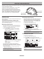
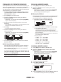
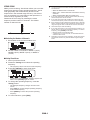
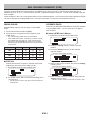
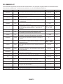
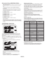
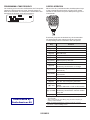
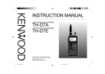
OPERATING THROUGH REPEATERS
Repeaters are often installed and maintained by radio clubs, sometimes with the cooperation of local businesses involved
in the communications industry.
Compared to simplex communication, you can usually
transmit over much greater distances by using a
repeater. Repeaters are typically located on mountain
tops or other elevated locations. They generally operate
at higher ERP (Effective Radiated Power) than a typical
station. This combination of elevation and high ERP
allows communications over considerable distances.
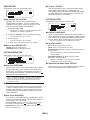
TX: 144.725 MHz
TX tone: 88.5 Hz
RX: 145.325 MHz
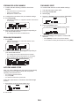
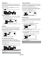
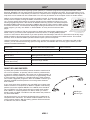
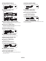
Repeater Access
nSelecting an Offset Frequency
Most repeaters use a receive and transmit frequency pair
with a standard or
non-standard offset (odd-split). In addition, some
repeaters must receive a tone from the transceiver in
order to gain access to the repeater. For details, consult
your local repeater reference.
The offset frequency is the value which the transmit
frequency will be offset from the receive frequency.
The default offset frequency on the 144 MHz band
is 600 kHz for all type versions. The default on the
430/440 MHz band is 5 MHz.
1 Select your desired band (A or B).
2 Enter Menu mode and access Menu 400.
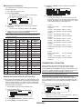
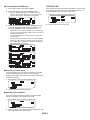
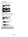
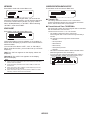
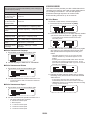
nSelecting an Offset Direction
TX: 144.725 MHz
TX tone: 88.5 Hz
RX: 145.325 MHz
The offset direction allows your transmit frequency to
be higher (+) or lower (–) than the receive frequency.
1 Select your desired band (A or B).
2 Press [F], [SHIFT] to select an offset direction.
3 Set the appropriate offset frequency value.
• Each time you press [SHIFT], the offset direction
changes as follows:
Simplex operation >> + >> – >> Simplex operation
• The selectable range is from 00.00 MHz to 29.95 MHz,
in steps of 50 kHz.
Note: After changing the offset frequency, the new offset
frequency will also be used by Automatic Repeater Offset.
n Activating the Tone Function
To turn the Tone function on:
1 Select your desired band (A or B).
2 Press [TONE] to turn the Tone function ON.
• If you are using an E type transceiver, when operating
on the 430 MHz band, the offset direction changes as
follows:
Simplex operation >> + >> – >> = (–7.6 MHz) >>
Simplex operation
• Each time you press [TONE], the selection changes as
follows:
Tone ( ) –> CTCSS ( ) –> DCS (
) –> Off (no
display).
• The icon appears on the display when the tone function is ON.
If the offset transmit frequency falls outside the
allowable range, transmitting is inhibited. Use one of
the following methods to bring the transmit frequency
within the band limits:
• Move the receive frequency further inside the band.
• Change the offset direction.
Note: While using an odd-split memory channel or transmitting,
you cannot change the offset direction.
Note: When accessing a repeater that requires a 1750 Hz tone,
you do not need to activate the Tone function. Simply press the
key assigned to the 1750 Hz tone {Menu 507 ~ 512} to transmit
the tone.
REPEATER-
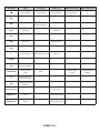
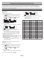
nSelecting a Tone Frequency
To select the tone frequency required to access your
desired repeater:
5 Rotate the Tuning control to select your desired
frequency.
1 Turn the Tone function ON.
2 Press [F], [T.SEL].
• The current tone frequency appears on the display.
The default frequency is 88.5 Hz.
6 Press [PTT] to start a call.
• You will be transmitting on an offset frequency value
determined from your offset setting value and an offset
direction depending on your selected frequency. Refer
to the settings below for offset directions:
K Type:
Under 145.100 MHz:
No offset (Simplex
operation)
145.100 ~ 145.499 MHz: Minus (–) offset
145.500 ~ 145.599 MHz: No offset (Simplex
operation)
146.000 ~ 146.399 MHz: Plus (+) offset
146.400 ~ 146.599 MHz: No offset (Simplex
operation)
146.600 ~ 146.999 MHz: Minus (–) offset
147.000 ~ 147.399 MHz: Plus (+) offset
147.400 ~ 147.599 MHz: No offset (Simplex
operation)
147.600 ~ 147.999 MHz: Minus (–) offset
148.000 MHz and higher:No offset (Simplex
operation)
3 Rotate the Tuning control to select your desired
frequency.
• To exit the tone frequency selection, press [ESC].
4 Press any key other than the Tuning control and
[ESC] to set the selected frequency.
Note: If you have set up a Memory channel with a tone setting,
simply recall the Memory channel instead of setting up the tone
frequency every time.
No.
Frequency
No.
(Hz)
Frequency
(Hz)
No.
Frequency
(Hz)
01
67.0
16
110.9
31
186.2
02
69.3
17
114.8
32
192.8
03
71.9
18
118.8
33
203.5
04
74.4
19
123.0
34
206.5
05
77.0
20
127.3
35
210.7
06
79.7
21
131.8
36
218.1
07
82.5
22
136.5
37
225.7
08
85.4
23
141.3
38
229.1
09
88.5
24
146.2
39
233.6
10
91.5
25
151.4
40
241.8
11
94.8
26
156.7
41
250.3
12
97.4
27
162.2
42
254.1
13
100.0
28
167.9
14
103.5
29
173.8
15
107.2
30
179.9
E Type:
Under 145.000 MHz:
No offset (Simplex
operation)
145.600 ~ 145.799 MHz: Minus (–) offset
145.800 MHz and higher:No offset (Simplex
operation)
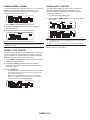
Transmitting a 1750 Hz Tone
Most repeaters in Europe require that a transceiver
transmit a 1750 Hz tone. On a E type model, simply
pressing Microphone [CALL] causes it to transmit a 1750
Hz tone. It is also possible to program [1750] on the front
panel as a PF key for transmitting a 1750 Hz tone.
Note: The transceiver continuously transmits a 1750 Hz tone until
you release Microphone [CALL] or PF key(1750).
n Automatic Repeater Offset (K and E Types Only)
This function automatically selects an offset direction and
activates the Tone function, according to the frequency
that you have selected. To obtain an up-to-date band
plan for repeater offset direction, contact your national
Amateur Radio association.
Some repeaters in Europe must receive continuous
signals for a certain period of time, following a 1750 Hz
tone. This transceiver is also capable of remaining in the
transmit mode for 2 seconds after transmitting a 1750 Hz
tone.
1 Enter Menu mode and access Menu 402.
1 Enter Menu mode and access Menu 401.
2 Set the ARO to ON.
2 Set the tone to ON or OFF.
• When set to ON, the 1750 Hz tone will transmit. When set
to OFF, the tone will not be transmitted.
3 Press [BAND SEL A] to select the A band.
4 Press [VFO] to select VFO mode.
Note: While remaining in the transmit mode, the transceiver does not
continuously transmit a 1750 Hz tone.
REPEATER-
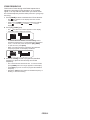
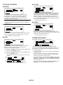
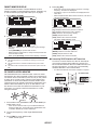
REVERSE FUNCTION
Tone Frequency ID
After setting a separate receive and transmit frequency,
you can exchange these frequencies using the Reverse
function. This allows you to manually check the strength
of signals you receive directly from other stations, while
using a repeater. If the station’s signal is strong, move to
a simplex frequency to continue the contact and free up
the repeater.
This function scans through all tone frequencies to identify
the incoming tone frequency on a received signal. You
can use this function to find which tone frequency is
required by your local repeater.
Press [REV] to turn the Reverse function ON or OFF.
2 Press [F], [T.SEL] (1s) to run the Tone Frequency ID
scan.
• When the Reverse function is ON, the
the display.
icon will appear on
Note:
u If the transmit frequency is outside the allowable transmit
frequency range when using Reverse, pressing [PTT] will cause
an error tone to sound and transmission will be inhibited.
u If the receive frequency is outside the receive frequency range
when using Reverse, an error tone will sound and Reverse will
not operate.
u The ARO (Automatic Repeater Offset) will not function when
Reverse is ON.
u You cannot switch Reverse ON or OFF while transmitting.
1 Press [TONE] to switch the Tone function ON.
• The
• The
icon appears on the display.
icon blinks and SCAN appears on the display.
• To reverse the scan direction, turn the Tuning control
clockwise (upward scan) or counterclockwise (downward
scan).
• To quit the function, press [ESC].
• When the tone frequency is identified, the identified
frequency appears on the display and blinks. Press any
key other than the Tuning control while the identified
frequency is blinking, to resume scanning.
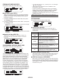
Automatic Simplex Checker (ASC)
While using a repeater, ASC periodically monitors the
strength of signals you receive directly from the other
stations. If the station’s signal is strong enough to allow
direct contact without a repeater, the icon blinks.
Press [REV] (1s) to turn the ASC ON.
• When the ASC is ON, the
icon will appear on the display.
3 Press the Tuning control to program the identified
frequency in place of the currently set tone frequency.
• The Tone function will remain ON. You can press [TONE]
to switch the Tone function OFF.
• Press [ESC] if you do not want to program the identified
frequency.
• While direct contact is possible, without the use of a repeater,
the icon will begin blinking.
• To exit ASC, press [REV].
Note:
Pressing [PTT] will cause the icon to stop blinking.
ASC does not function if you are using simplex operation.
ASC does not function while scanning.
Activating ASC while using Reverse will switch the Reverse
function OFF.
u If you recall a Memory channel or the Call channel, and those
channels are set up with the Reverse function switched ON, the
ASC will switch OFF.
u You cannot use ASC when the built-in TNC is turned ON.
u ASC causes received signals to be momentarily intermitted every
3 seconds.
u
u
u
u
REPEATER-
MEMORY CHANNELS
In Memory channels, you can store frequencies and related data that you often use. Then you need not reprogram the
data every time. You can quickly recall a programmed channel by simple operation. A total of 1000 Memory channels
are available for bands A and B.
SIMPLEX & REPEATER OR ODD-SPLIT MEMORY
CHANNEL?
Storing Simplex and Standard Repeater
Frequencies
You can use each memory channel as a simplex &
repeater channel or as an odd-split channel. Store only
one frequency to use as a simplex & repeater channel or
two separate frequencies to use as an odd-split channel.
Select either application for each channel depending on
the operations you have in mind.
1 Press [VFO] to enter VFO mode.
Simplex & repeater channels allow:
3 Set up any additional data desired for the frequency.
2 Rotate the Tuning control to select your desired
frequency.
• Additionally, you can press the microphone [UP]/[DWN]
keys to select a frequency.
• Offset direction, Tone ON/OFF, Tone frequency, CTCSS
ON/OFF, CTCSS frequency, DCS ON/OFF, DCS code,
etc.
• Simplex frequency operation
• Repeater operation with a standard offset (if an offset
direction is stored)
4 Press [F].
• A memory channel number appears.
Odd-split channels allow:
• Repeater operation with a non-standard offset
The data listed below can be stored in each Memory
channel:
Parameter
Receive frequency
Transmit frequency
Receive frequency
step size
Transmit frequency
step size
Simplex &
Repeater
Yes
Odd-split
Yes
5 Rotate the Tuning control to select your desired
channel number.
• Additionally, you can press the microphone [UP]/[DWN]
keys to select a channel.
Yes
Yes
6 Press [M.IN] to store the data in the selected Memory
channel.
Yes
Note: If you store the data in a Memory channel that already has
data stored in it, the old data will be cleared and the new data will be
stored.
Yes
Offset direction
Yes
No
Tone ON/OFF
Yes
Yes
Tone frequency
Yes
Yes
CTCSS ON/OFF
Yes
Yes
CTCSS frequency
Yes
Yes
DCS ON/OFF
Yes
Yes
DCS code
Yes
Yes
Reverse ON/OFF
Yes
No
Memory channel
lockout
Yes
Yes
Memory channel
name
Yes
Yes
Modulation/
Demodulation mode
Yes
Yes
n Call Channel Memory (Simplex)
The Call channel can be used to store any frequency
and related data that you will recall often. You may
want to dedicate the Call channel as an emergency
channel within your group.
To store a simplex frequency and related data as the
Call channel instead of in a Memory channel, after step
4 (above), press [C.IN].
Note: Storing new data in the Call channel will clear the old
data. (The Call channel itself cannot be cleared, but data can be
replaced with new data.)
MEMORY CH-
Storing Odd-Split Repeater Frequencies
Recalling a Memory Channel
Some repeaters use a receive and transmit frequency pair
with a non-standard offset. To access those repeaters,
store two separate frequencies in a memory channel. You
can then operate on those repeaters without changing the
offset frequency you stored in the menu.
1 Press [MR] to enter Memory Recall mode.
2 Rotate the Tuning control to select your desired
Memory channel.
• Additionally, you can press the microphone [UP]/[DWN]
keys to select a channel, or you can enter a channel
number using the microphone keypad.
1 Set up a simplex channel by following steps 1 to 6 of
“STORING SIMPLEX AND STANDARD REPEATER
FREQUENCIES”, above.
n Memory Recall Method
2 Press [VFO] to enter VFO mode.
3 Rotate the Tuning control to select your desired
transmit frequency.
• Additionally, you can press the microphone [UP]/[DWN]
keys to select a frequency.
The transceiver Menu also provides you with the option
to recall Memory channels with stored frequencies in
your current band, or all Memory channels:
1 Enter Menu mode and access Menu 201.
4 Set up any additional data desired for the transmit
frequency.
• Tone ON/OFF, Tone frequency, CTCSS ON/OFF, CTCSS
frequency, DCS ON/OFF, DCS code, etc.
2 Set the recall method to CURRENT (current band)
or ALL BANDS (all bands).
5 Press [F].
• A memory channel number appears.
• CURRENT allows you to recall only those memory
channels that have stored frequencies within the
current band. ALL allows you to recall all programmed
memory channels.
• When the recalled memory channel is an AM channel,
you cannot recall on the B band.
Frequency ranges:
• 118 MHz: 118 ~ 135.995 MHz
• 144 MHz: 136 ~ 199.995 MHz
• 220 MHz: 200 ~ 299.995 MHz
• 300 MHz: 300 ~ 399.995 MHz
• 430/440 MHz: 400 ~ 523.995 MHz
• 1200 MHz: 800 ~ 1299.990 MHz
6 Rotate the Tuning control to select your desired
channel number.
• Additionally, you can press the microphone [UP]/[DWN]
keys to select a channel.
7 Press [PTT], [M.IN] to store the data in the selected
Memory channel.
n Call Channel Memory (Odd-Split)
The Call channel can be used to store any frequency
and related data that you will recall often. You may
want to dedicate the Call channel as an emergency
channel within your group.
To store an odd-split frequency and related data as the
Call channel instead of in a Memory channel, after step
6 (above), press [PTT], [C.IN].
Note: You cannot store the transmit offset status and Reverse
status in an odd-split Call channel.
Clearing a Memory Channel
1 Press [MR] to enter Memory Recall mode.
2 Rotate the Tuning control to select your desired
Memory channel.
• Additionally, you can press the microphone [UP]/[DWN]
keys to select a channel, or you can enter a channel
number using the microphone keypad.
3 Turn the transceiver power OFF.
4 Press [MR] + Power ON.
• A confirmation message appears on the display.
5 Press the Tuning control to clear the Memory channel.
• To exit without clearing the channel, press [ESC].
MEMORY CH-
Naming a Memory Channel
Channel Display Function
You can name Memory channels using up to 8 characters.
When you recall a named Memory channel, its name
appears on the display. Names can be call signs,
repeater names, cities, people, etc.
Use this function when you want to use only Memory
channels. When this function is switched ON, the
transceiver displays only a Memory channel number
instead of a frequency.
1 Turn the transceiver power OFF.
2 Press [LOW] + Power ON to turn the channel display
ON or OFF.
1 Press [MR] to enter Memory Recall mode.
2 Rotate the Tuning control to select your desired
Memory channel.
3 Enter Menu mode and access Menu 200.
4 Enter your desired name for the channel.
Note: You can overwrite a Memory channel name by performing the
steps above. You can also clear a Memory channel name by clearing
the Memory channel.
Note:
u If no Memory channels have saved data in them, channel display
will not function.
u When using Channel Display, you cannot reset the transceiver.
While in Channel Display mode, the transceiver keys
function as shown next page:
Memory-TO-VFO Transfer
Transferring the contents of a Memory channel or the Call
channel to the VFO can be useful if you want to search
for other stations or a clear frequency, near the selected
Memory channel or Call channel frequency.
1 Press [MR] or [CALL] to enter Memory Recall mode or
select the Call channel.
2 Rotate the Tuning control to select your desired
channel. (This step is not necessary when selecting
the Call channel.)
3 Press [F], [M>V].
• The entire contents of the Memory channel or Call channel
are copied to the VFO, and VFO mode is selected after
the transfer is complete.
• When copying a transmit frequency from an odd-split
Memory or Call channel, you must first turn the Reverse
function ON before pressing [F], [M>V].
MEMORY CH-
Key Name
[KEY]
[F], [KEY]
[KEY] (1s)
While Transmitting
[KEY] + Power ON
Power ON/OFF
Power ON/OFF
Power ON/OFF
Power ON/OFF
X
PM
–
–
–
–
–
TNC
–
DX PacketClusters
Monitor ON/OFF
–
–
–
CALL
Call mode
–
Call Scan
–
–
VFO
–
–
–
–
–
MR
MR mode
–
Memory Scan
–
–
KEY
–
–
–
–
–
F
Function mode
Exit Function mode
Key Lock
–
–
TONE
–
–
–
–
–
REV
Reverse ON/OFF
–
–
–
–
LOW/ MUTE
Change output
power
Mute
–
Change output
power
Change channel
display
PF1
Select the Weather
channel (K type)
–
–
–
–
PF2
Change control band
(default)
–
–
–
–
Tuning control
–
–
Group Scan
–
–
BAND SEL A
A band
–
Change Single/Dual
–
–
BAND SEL B
B band
–
Change Single/Dual
–
–
MEMORY CH-
PROGRAMMABLE MEMORY (PM)
Programmable Memory (PM) stores virtually all settings currently set on the transceiver. This transceiver provides 5 PM
channels to store 5 sets of transceiver configurations. Later, you can quickly recall any one of these channels, depending
on the operations you have in mind or the operating environment.
The following programmable settings cannot be stored:
Application Examples
• Memory name
The following are examples of how you might use
Programmable Memory. These examples may not
represent applications useful to you, but you will
understand the flexibility of this function.
• Memory channel lockout
• Channel Display mode
• Locked-band/ Cross-band Repeater ON/OFF 1
• Repeater mode 1
• Repeater hold
1
• Repeater ID transmit 1
• Registered repeater ID 1
• Wireless remote control 1
• Answer back 1
• Remote control ID 1
• Key lock
• Power on password 2
• Memory channel/ Call channel/ Program scan memory
• Weather channel 1
• DTMF memory
• EchoLink memory
• COM port speed
• PC port speed
• 10 MHz mode 2
• Mic sensitivity
2
• SQC data output logic 2
1
2
K type only
Can be set only by using the MCP-2A software.
Situation: You share your transceiver with other
members in your family or club. However, each individual
has personal preferences for how they like to set various
functions. You have to keep changing many settings each
time you use the transceiver.
Solution: Because 5 PM channels are available, up to 5
persons can separately program the transceiver and store
their customized environment. Then each person can
quickly change to his or her favorite settings, simply by
recalling a PM channel. It is too much trouble to change
back the settings after somebody else has reconfigured
them. So this application may avoid having a feature-rich
transceiver but never using many useful features.
Situation: While operating mobile on the way to work
every morning, you prefer a silent transceiver that does
not interrupt the morning calm. In addition, you feel that
a bright display is useless in the sunlight. At night when
driving home, you realize the Beep function truly does
serve a purpose and you acknowledge it is nice to see a
bright display after dark.
Solution: In 2 PM channels, store the same operating
data such as frequency, offset, tone, etc, and store
different settings for the Display brightness and Beep
functions. Then you can quickly recall the best settings for
day or night operation.
Situation: You cannot figure out how to exit the current
transceiver mode.
Solution: Simply recall PM channel 1, which contains an
exact copy of the transceiver default environment. You
will not lose the contents of any memory channels.
Downloaded by
RadioAmateur.EU
PM-
Storing Data in PM Channels
PM Channel Reset
1 Confirm that the following conditions have been
satisfied:
To reset the PM channels to their default settings:
1 Turn the transceiver power OFF.
• The transceiver is in receive mode.
• Scan is not being used.
• Microphone Control is OFF.
2 Press [F] + Power ON.
3 Release [F].
4 Rotate the Tuning control and select PM RESET.
2 Configure the transceiver with your desired settings.
3 Press [F], [P.IN].
• PM channel numbers 1 to 5 appear and blink at the bottom
of the display.
5 Press the Tuning control.
• A confirmation message appears on the display.
4 Enter a channel number ([1] to [5]) corresponding to
your desired PM channel.
• The settings are stored in the PM channel.
Recalling PM Channels
6 Press the Tuning control again to reset the PM
channels.
• Press [BACK] to return to the previous display.
• To exit without resetting the PM channels, press [ESC].
1 Press [PM].
• PM channel numbers 1 to 5 and OFF appear on the
bottom of the display.
2 Enter a channel number ([1] to [5]) corresponding to
your desired PM channel.
• The settings stored in the PM channel are recalled.
• The selected channel number appears on the display.
• When selecting [OFF], the PM channels turn off.
Auto PM Channel store
After you recall a PM channel, this function automatically
overwrites the current PM channel with the present
operating environment when:
• You recall another PM channel.
• You press [PM].
• You switch the transceiver power OFF.
Follow the steps below to activate the Auto PM storage
function.
1 Enter Menu mode and access Menu 521.
2 Set to ON.
PM-
SCAN
Scan is a useful feature for hands-off monitoring of your favorite frequencies. Becoming comfortable with all types of
Scan will increase your operating efficiency.
This transceiver provides the following types of scans:
Scan Type
VFO Scan
Memory Scan
Group Scan
Program Scan
Scan Range
Scans all frequencies on the current band.
Scans all frequencies stored in the Memory channels.
Scans the frequencies in the Memory channels which belong to the group you have
specified.
Scans all frequencies within the programmed range, on the current band.
MHz Scan
Scans all frequencies within a 1 MHz range from the originating frequency.
Call Scan
Scans the Call channel as well as the currently selected VFO frequency or Memory
channel.
Note:
u Adjust the squelch level before using Scan. Selecting a squelch level too low could cause Scan to stop immediately.
u While using CTCSS or DCS, Scan stops for any signal received; however, you will hear audio only when the signal contains the same CTCSS
tone or DCS code that you selected.
u When using S-meter Squelch, Scan stops when the received signal strength matches or exceeds the S-meter setting. Scan resumes 2 seconds
after the signal level drops below the S-meter setting.
u Pressing and holding [PTT] causes Scan to temporarily stop if it is functioning on a non TX band.
u Starting Scan switches the Automatic Simplex Checker OFF.
SELECTING a SCAN RESUME METHOD
VFO SCAN
The transceiver stops scanning at a frequency or Memory
channel on which a signal is detected. It then continues
scanning according to which resume mode you have
selected. You can choose one of the following modes.
The default is Time-operated mode.
VFO Scan monitors all frequencies tunable on the band,
using the current frequency step size.
1 Select your desired band.
2 Press [VFO] (1s).
• Scan starts at the current frequency.
• The 1 MHz decimal blinks while scanning is in progress.
• To reverse the scan direction, turn the Tuning control
clockwise (upward scan) or counterclockwise (downward
scan). You can also press microphone [UP]/ [DWN].
• Time-Operated mode
The transceiver remains on a busy frequency or
Memory channel for approximately 5 seconds, and
then continues to scan even if the signal is still present.
• Carrier-Operated mode
The transceiver remains on a busy frequency or
Memory channel until the signal drops out. There is
a 2 second delay between signal drop-out and scan
resumption.
• Seek mode
The transceiver remains on a busy frequency or
Memory channel even after the signal drops out and
does not automatically resume scanning.
3 To quit VFO Scan, press [VFO] again.
Note: To temporarily stop scanning and monitor weak signals, press
the microphone PF key assigned to the Monitor function. Press the
PF key again to resume scanning.
1 Enter Menu mode and access Menu 514.
2 Set the Scan Resume mode to TIME (Time-Operated),
CARRIER (Carrier-Operated) or SEEK.
SCAN-
MEMORY SCAN
1 Press [MR], then rotate the Tuning control to select a
channel in your desired group.
Use Memory Scan to monitor all Memory channels
programmed with frequency data.
2 Press the Tuning control (1s).
• Scan starts at the current channel.
• The 1 MHz decimal blinks while scanning is in progress.
• To reverse the scan direction, turn the Tuning control
clockwise (upward scan) or counterclockwise (downward
scan). You can also press microphone [UP]/ [DWN].
1 Select your desired band.
2 Press [MR] (1s).
v Scan starts at the current frequency.
• The 1 MHz decimal blinks while scanning is in progress.
• To reverse the scan direction, turn the Tuning control
clockwise (upward scan) or counterclockwise (downward
scan). You can also press microphone [UP]/ [DWN].
3 To quit Group Scan, press the Tuning control again.
Note:
u At least 2 Memory channels in the selected group must contain
data and must not be locked out of scan.
u You can also start Memory Scan when in Channel Display mode.
While Scan is paused on a channel, the channel number blinks.
3 To quit Memory Scan, press [MR] again.
Note:
u At least 2 Memory channels must contain data and must not be
locked out of scan.
u The L0/U0 to L9/U9 Memory channels will not be scanned.
u You can also start Memory Scan when in Channel Display mode.
While Scan is paused on a channel, the channel number blinks.
n Memory Group Link
n Locking Out a Memory Channel
You can select Memory channels that you prefer not to
monitor while scanning.
1 Press [MR], then rotate the Tuning control to select
your desired channel.
2 Enter Menu mode and access Menu 202.
Memory Group Link provides you with the ability to
link 2 or more Memory channel groups together to act
as a single group when scanning. You can link up
to 10 separate groups together, or even add multiple
instances of the same group to the group link, to
ensure that one group is scanned more often than the
other groups.
1 Enter Menu mode and access Menu 203.
2 Press the Tuning control.
• The cursor will begin blinking.
3 Set the lockout to ON to lock the channel out of the
scanning sequence.
• To cancel lockout, set the lockout to OFF.
3 Rotate the Tuning control to select a group to link.
• The icon appears on the display for a channel
that has been locked out.
4 Press the Tuning control to set the group and move
the cursor to the right.
• Press [ ] to move the cursor back or [ ] to move the
cursor to the right.
5 Repeat steps 3 and 4 to link additional groups
together.
Note: The L0/U0 to L9/U9 Memory channels cannot be locked
out.
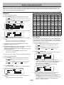
GROUP SCAN
6 When you have entered your desired groups, press
[ ] to move the cursor to the right, then press the
Tuning control to complete the entry and exit Menu
mode.
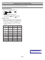
For the purpose of Group Scan, the 1000 Memory
channels are divided into 10 groups, with each group
containing 100 channels. Group Scan monitors only the
100 channels which belong to the specific group you are
scanning. The channels are grouped as follows:
Memory
Group
Channel
Range
Memory
Group
Channel
Range
0
0 ~ 99
5
500 ~ 599
1
100 ~ 199
6
600 ~ 699
2
200 ~ 299
7
700 ~ 799
3
300 ~ 399
8
800 ~ 899
4
400 ~ 499
9
900 ~ 999
• You can insert one space by pressing [SPACE].
• You can insert a character by pressing [INS].
• You can delete the selected character by pressing
[CLR].
• If you have entered the maximum of 6 groups, simply
press the Tuning control to complete the entry and exit
Menu mode.
SCAN-
PROGRAM SCAN
5 To quit Program Scan, press [VFO] again.
Note:
u If the step size differs between the lower limit and upper limit,
VFO scan will begin instead of Program Scan.
u If the current VFO frequency is within more than one Program
Scan range, the range stored in the smallest channel number
is used.
Program Scan is identical to VFO Scan except that you
select a frequency range for the scan.
n Setting Scan Limits
You can store up to 10 scan ranges in Memory
channels L0/U0 to L9/U9.
1 Press [VFO].
MHz SCAN
2 Select your desired band.
MHz Scan monitors a 1 MHz segment of the band, using
the current frequency step size. The current 1 MHz digit
determines the limits of the scan. For example, if the
current frequency is 145.400 MHz, then the scan range
would be from 145.000 MHz to 145.995 MHz (the exact
upper limit depends on the current frequency step size).
3 Rotate the Tuning control to select your desired
frequency for the lower limit.
1 Select your desired band.
2 Press [VFO].
4 Press [F].
• A memory channel number appears and blinks.
5 Rotate the Tuning control to select a channel from
L0 to L9.
5 To quit MHz Scan, press the Tuning control again.
• The lower limit is stored in the channel.
7 Rotate the Tuning control to select your desired
frequency for the lower limit.
CALL SCAN
8 Press [F].
Use Call Scan to monitor both the Call channel and either
the currently selected VFO frequency or the currently
selected Memory channel.
9 Rotate the Tuning control to select a matching
channel number from U0 to U9.
• For example, if you select channel L3 in step 5, select
channel U3 here.
• The upper limit is stored in the channel.
4 Press and hold the Tuning control for 1 second to start
scanning.
• Scan starts at the current frequency.
• The 1 MHz decimal blinks while scanning is in progress.
• To reverse the scan direction, turn the Tuning control
clockwise (upward scan) or counterclockwise (downward
scan). You can also press microphone [UP]/ [DWN].
6 Press [M.IN] to set the channel number.
10Press [M.IN] to set the channel number.
3 Rotate the Tuning control to select a frequency within
your desired 1 MHz range.
1 Select your desired VFO frequency or Memory
channel.
2 Press [CALL] (1s) to start Call Scan.
• The 1 MHz decimal blinks while scanning is in progress.
• When scanning a Memory channel, the Call channel on
the same band as the selected Memory channel is used
for scan.
• To confirm the stored scan limits, press [MR],
then select the L and U channels.
Note:
u The lower limit must be lower in frequency than the upper
limit.
u The lower and upper frequency step sizes must be equal.
u The lower and upper limits must be selected on the same
band.
3 To quit Call Scan, press [CALL] again.
Note: The Memory channel selected is scanned even if it has been
locked out of scan.
n Using Program Scan
1 Select your desired band.
2 Press [VFO].
3 Rotate the Tuning control to select a frequency
within your desired scan range.
4 Press [VFO] (1s).
• Scan starts at the current frequency.
• The 1 MHz decimal blinks while scanning is in
progress.
• To reverse the scan direction, turn the Tuning
control clockwise (upward scan) or counterclockwise
(downward scan). You can also press microphone
[UP]/ [DWN].
SCAN-
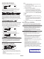
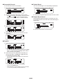
VISUAL SCAN
While you are receiving, Visual Scan allows you to monitor
frequencies near the current operating frequency. Visual
Scan graphically and simultaneously shows how all
frequencies in the selected range are busy. You will see
up to 21 segments, for each channel, that represent 7 Smeter levels (3 segments per level).
S-meter level
Determine the scan range by selecting the center
frequency and the number of channels. The default
number of channels is 61.
Cursor
n Selecting the Number of Channels
1 Enter Menu mode and access Menu 515.
2 Set the number of channels to MODE 1 (31ch),
MODE 2 (61ch), MODE 3 (91ch), or MODE 4
(181ch).
n Using Visual Scan
1 Select your desired band.
2 Rotate the Tuning control select the operating
frequency.
• This frequency will be used as the center frequency.
3 Press [F], [VISUAL] to start Visual Scan.
• To halt Scan, press [PAUSE]. “PAUSE” appears and
blinks. Press [PAUSE] again to resume.
4 To change the operating frequency, rotate the
Tuning control.
• The displayed frequency changes and the cursor
moves.
• Press [SET] to use the changed operating frequency
as the center frequency.
• Press [RESET] to restore the previous operating
frequency.
5 To exit Visual Scan, press [ESC].
SCAN-
Note:
u You cannot use the Visual Scan Function under the following
circumstances:
• When the Built-in TNC is turned ON.
• When only 1 channel has been stored in the memory
channels.
• When using Weather Alert (K models only).
u If you start Visual Scan in Memory Recall mode, the memory
channel frequencies will be scanned.
u If you start Visual Scan after recalling the Call channel, the
Call channel frequency will be used as the center frequency.
u If the frequency range specified for Program Scan or Program
VFO is narrower than the range specified for Visual Scan, the
range for Program Scan or VFO will be used for Visual Scan.
u Visual Scan stops while transmitting.
u If you start Visual Scan in one of the following conditions, you
cannot receive in the current operating frequency. To use this
frequency, press [PAUSE] to halt Scan.
• Memory Recall or Call Channel mode.
• A frequency in the 118, 220, 300, or 1200 MHz band was
selected in VFO mode.
u Depending on the transceiver conditions, Visual Scan and the
conventional S-meter may indicate different signal strength
levels.
CONTINUOUS TONE CODED SQUELCH SYSTEM (CTCSS)
You may sometimes want to hear calls only from specific persons. The Continuous Tone Coded Squelch System
(CTCSS) allows you to ignore (not hear) unwanted calls from other persons who are using the same frequency. To do
so, select the same CTCSS tone as selected by the other persons in your group. A CTCSS tone is subaudible and is
selectable from among 42 tone frequencies.
Note: CTCSS does not cause your conversation to be private. It only relieves you from listening to unwanted conversations.
USING CTCSS
1 Select your desired band.
2 Press [TONE] 2 times to activate the CTCSS function.
• The
icon appears on the display when the CTCSS
function is ON.
• Each press of [TONE] changes the selection as follows:
Tone ( ) –> CTCSS ( ) –> DCS (
) –> Off (no
display).
5 Enter a frequency reference number (01 ~ 42) using
the microphone keypad.
• Refer to the table below for frequencies and their
reference numbers.
No.
Frequency
No.
(Hz)
Frequency
(Hz)
No.
Frequency
(Hz)
01
67.0
16
110.9
31
186.2
02
69.3
17
114.8
32
192.8
03
71.9
18
118.8
33
203.5
04
74.4
19
123.0
34
206.5
05
77.0
20
127.3
35
210.7
06
79.7
21
131.8
36
218.1
07
82.5
22
136.5
37
225.7
08
85.4
23
141.3
38
229.1
09
88.5
24
146.2
39
233.6
10
91.5
25
151.4
40
241.8
5 Press any key other than the Tuning control and
[ESC] to complete the setting.
11
94.8
26
156.7
41
250.3
12
97.4
27
162.2
42
254.1
6 When you are called: The transceiver squelch opens only
when the selected CTCSS tone is received.
When you make a call: Press and hold [PTT], then speak
into the microphone.
13
100.0
28
167.9
14
103.5
29
173.8
15
107.2
30
179.9
3 Press [F], [T.SEL].
• The current CTCSS frequency appears on the display and
blinks.
4 Rotate the Tuning control to select your desired
CTCSS frequency.
• Refer to the table below for the available frequencies.
• To exit the CTCSS frequency selection, press [ESC].
• To cancel CTCSS, press [TONE] until CT no longer
appears on the display.
You can also select a CTCSS frequency by using the
microphone:
1 Select your desired band.
2 Press [TONE] 2 times to activate the CTCSS function.
• The
icon appears on the display when the CTCSS
function is ON.
• Each press of [TONE] changes the selection as follows:
Tone ( ) –> CTCSS ( ) –> DCS (
) –> Off (no
display).
3 Press [F], [T.SEL].
• The current CTCSS frequency appears on the display and
blinks.
4 Press the key programmed as [ENTER].
CTCSS-
CTCSS Frequency ID
This function scans through all CTCSS frequencies to
identify the incoming CTCSS frequency on a received
signal. You may find this useful when you cannot recall
the CTCSS frequency that the other persons in your group
are using.
1 Press [TONE] 2 times to activate the CTCSS function.
• The
icon appears on the display when the CTCSS
function is ON.
• Each press of [TONE] changes the selection as follows:
Tone ( ) –> CTCSS ( ) –> DCS (
) –> Off (no
display).
2 Press [F], [T.SEL] (1s).
• The
icon blinks and “SCAN” appears on the display.
• Scan starts when a signal is received.
• To reverse the scan direction, turn the Tuning control
clockwise (upward scan) or counterclockwise (downward
scan). You can also press microphone [UP]/ [DWN].
• To quit the scan, press [ESC].
• When a CTCSS frequency is identified, the identified
frequency appears on the display and blinks.
3 Press the Tuning control to program the identified
frequency in place of the currently set CTCSS
frequency.
• The CTCSS function will remain ON. To cancel CTCSS,
press [TONE] until CT no longer appears on the display.
• Press [ESC] if you do not want to program the identified
frequency.
• Rotate the Tuning control while an identified frequency is
blinking, to resume scanning.
CTCSS-
DIGITAL CODED SQUELCH (DCS)
Digital Code Squelch (DCS) is another application which allows you to ignore (not hear) unwanted calls. It functions the
same way as CTCSS. The only differences are the encode/ decode method and the number of selectable codes. For
DCS, you can select from 104 different codes.
USING DCS
DCS Code
1 Select your desired band.
023
025
026
031
032
036
043
047
2 Press [TONE] 3 times to activate the DCS function.
051
053
054
065
071
072
073
074
114
115
116
122
125
131
132
134
143
145
152
155
156
162
165
172
174
205
212
223
225
226
243
244
245
246
251
252
255
261
263
265
266
271
274
306
311
315
325
331
332
343
346
351
356
364
365
371
411
412
413
423
431
432
445
446
452
454
455
462
464
465
466
503
506
516
523
526
532
546
565
606
612
624
627
631
632
654
662
664
703
712
723
731
732
734
743
754
• The
icon appears on the display when the DCS
function is ON.
• Each press of [TONE] changes the selection as follows:
Tone ( ) –> CTCSS ( ) –> DCS (
) –> Off (no
display).
3 Press [F], [T.SEL].
• The current DCS code appears on the display and blinks.
DCS Code ID
4 Rotate the Tuning control to select your desired DCS
code.
This function scans through all DCS codes to identify the
incoming DCS code on a received signal. You may find it
useful when you cannot recall the DCS code that the other
persons in your group are using.
• Refer to the table below for the available codes.
• To exit the DCS code selection, press [ESC].
5 Press any key other than the Tuning control and
[ESC] to complete the setting.
1 Press [TONE] 3 times to activate the DCS function.
• The
icon appears on the display when the DCS
function is ON.
• Each press of [TONE] changes the selection as follows:
Tone ( ) –> CTCSS ( ) –> DCS (
) –> Off (no
display).
6 When you are called: The transceiver squelch opens only
when the selected DCS code is received.
When you make a call: Press and hold [PTT], then speak
into the microphone.
• To cancel DCS, press [TONE] until DCS no longer
appears on the display.
2 Press [F], [T.SEL] (1s).
• The
icon blinks and “SCAN” appears on the display.
• Scan starts when a signal is received.
You can also select a DCS code by using the microphone:
1 Select your desired band.
2 Press [TONE] 3 times to activate the DCS function.
• The
icon appears on the display when the DCS
function is ON.
• Each press of [TONE] changes the selection as follows:
Tone ( ) –> CTCSS ( ) –> DCS (
) –> Off (no
display).
• To reverse the scan direction, turn the Tuning control
clockwise (upward scan) or counterclockwise (downward
scan). You can also press microphone [UP]/ [DWN].
• To quit the scan, press [ESC].
• When a DCS code is identified, the identified code
appears on the display and blinks.
3 Press [F], [T.SEL].
• The current DCS code appears on the display and blinks.
4 Press the key programmed as [ENTER].
3 Press the Tuning control to program the identified
code in place of the currently set DCS code.
5 Enter your desired DCS code using the microphone
keypad.
• Refer to the table below for DCS codes.
DCS-
• The DCS function will remain ON. To cancel DCS, press
[TONE] until DCS no longer appears on the display.
• Press [ESC] if you do not want to program the identified code.
• Rotate the Tuning control while an identified code is
blinking, to resume scanning.
DUAL TONE MULTI-FREQUENCY (DTMF)
The keys on the microphone keypad function as DTMF keys; the 12 keys found on a push-button telephone plus 4
additional keys (A, B, C, D). This transceiver provides 10 dedicated memory channels. You can store a DTMF code with
up to 16 digits.
Some repeaters in the U.S.A. and Canada offer a service called Autopatch. You can access the public telephone network
via such a repeater by sending DTMF tones. For further information, consult your local repeater reference.
Manual Dialing
Automatic Dialer
Manual Dialing requires only two steps to send DTMF
tones.
There are 10 dedicated DTMF Memory channels available
to store DTMF codes. You can store up to 16 digits in
each channel.
1 Press and hold the microphone [PTT].
n Storing a DTMF Code in Memory
2 Press the keys in sequence on the keypad to send
DTMF tones.
• The corresponding DTMF tones are transmitted.
• If the DTMF Hold function is activated, you need not hold
down [PTT] while pressing keys. After transmitting the
first tone (by pressing [PTT] and the first key), pressing
additional keys will keep the transceiver in transmit mode
for 2 seconds.
Frequency (Hz)
1209
1336
1447
1633
697
[1]
[2]
[3]
[A]
770
[4]
[5]
[6]
[B]
852
[7]
[8]
[9]
[C]
941
[ ]
[0]
[#]
[D]
1 Enter Menu mode and access Menu 301.
2 Rotate the Tuning control to select a channel
number.
3 Press the Tuning control to set the selected
channel number.
• The name entry display appears.
n DTMF Hold
Activate this function to remain in transmit mode, after
beginning to press keys when making a call.
1 Enter Menu mode and access Menu 300.
2 Set DTMF Hold to ON to continue transmitting when
pressing keys.
• Set this menu to OFF to stop the 2 second continuous
transmission.
DTMF-
4 Enter a name for the channel, the press the Tuning
control to set it.
• The code entry display appears.
5 Enter a DTMF code for the channel, then press the
Tuning control to set it.
• When a space is entered, it becomes a “Pause” code.
DTMF Key Lock
n Transmitting Stored DTMF Codes
1 Press and hold the microphone [PTT].
This function will lock the DTMF transmission keys so that
they will not transmit if they are accidentally pressed. To
lock the DTMF keys, turn this function ON.
2 While transmitting, press the Tuning control.
• The last called DTMF Memory channel name and
number appear on the display. If no name has been
saved for the channel, the DTMF code appears.
1 Enter Menu mode and access Menu 304.
3 While still transmitting, rotate the Tuning control to
select your desired DTMF Memory channel, then
press the Tuning control to set the channel.
2 Set the key lock to ON or OFF.
• Additionally, you can press a DTMF key corresponding
to your desired channel ([0] ~ [9]) to select the channel
and begin transmission.
• The stored DTMF code scrolls across the display and
is transmitted.
• The code will be transmitted even if you release [PTT]
before the entire code has scrolled across the display.
• If no DTMF code is stored in the selected channel, the
frequency display is restored.
n Selecting a Transmit Speed
Some repeaters may not respond correctly if a DTMF
code is transmitted at fast speed. If this happens,
change the DTMF code transmission speed from FAST
(default) to SLOW.
1 Enter Menu mode and access Menu 302.
2 Set the speed to FAST or SLOW.
n Selecting a Pause Duration
You can change the pause duration stored in DTMF
Memory channels; the default is 500 msec.
1 Enter Menu mode and access Menu 303.
2 Select a speed (in msec) from the available list: 100/
250/ 500/ 750/ 1000/ 1500/ 2000.
DTMF-
EchoLink®
What is EchoLink?
EchoLink allows you to communicate with other amateur radio stations over the internet, using VoIP (voice-over-IP)
technology. The EchoLink software program allows worldwide connections to be made between stations, or from
computer to station, greatly enhancing your communications capabilities.
To use EchoLink, you must register using your call sign on their website and download the EchoLink software program
(free of charge). Refer to the website for PC hardware and other requirements.
Official EchoLink Website: http://www.echolink.org
Note: EchoLink is a registered trademark of Synergenics, LLC.
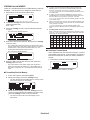
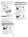
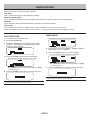
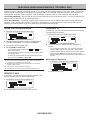
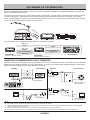
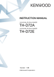
Setting Up EchoLink Sysop MODE
Connect the TM-D710 to a personal computer to use
the system as a base station (link bureau) for EchoLink
relaying.
When connecting to a personal computer and using the
EchoLink Sysop mode, the hard flow control operation
RTS and CTS computer terminals operate the same as
and are changed with the SQC (squelch control signal
output to the computer) and PKS (transmit control signal
input from the computer) data terminals.
The current band becomes the same as the data band
which is selected in menu No. 517, regardless of the
transmission band and operation band.
Note:
u You cannot use EchoLink Sysop mode when the built-in TNC is
turned ON.
u We recommend you set Menu 520’s SQC output setting to SQL
when using EchoLink Sysop mode.
u When a noise or other such signal is sent from the link bureau
to the internet when using CTCSS and DCS, set the EchoLink
“RX Monitor” function to “Busy only” (this can only be set with the
MCP-2A) to verify the usage condition of the operating frequency.
Because of this, when EchoLink Sysop mode is ON, all received
signals on the EXT.DATA band side are output through the
speaker, regardless of a CTCSS and DCS mismatch. (When
CTCSS and DCS matches, only the voice signal is output from
the data terminal.)
u When EchoLink Sysop mode is ON, it cannot communicate with
the MCP-2A. When using the MCP-2A, be sure to turn EchoLink
Sysop mode OFF.
Use the PG-5H (interface cable kit) when connecting to a
personal computer.
1 Turn the transceiver power OFF.
2 Press [PF2] + Power ON to turn EchoLink Sysop
Mode ON.
• The
icon appears on the display when EchoLink Sysop
mode is ON.
• When the MCP-2A “EchoLink RX Monitor” is turned ON
and an audio signal is output to the PC side, the
icon
blinks.
• To turn EchoLink Sysop Mode OFF, press [PF2] + Power
ON again.
EchoLink Sysop Mode
ON
PC
terminal
EchoLink Sysop Mode
OFF
PC
PC
terminal
PC
TxD
–>
RxD
TxD
–>
RxD
RxD
<–
TxD
RxD
<–
TxD
SQC
–>
CTS
RTS
–>
CTS
PKS
<–
RTS
CTS
<–
RTS
GND
<–>
GND
GND
<–>
GND
EchoLink-
Storing EchoLink memory
Note:
u In step 2, press the microphone [C] key before pressing the
Tuning control, to transmit the converted DTMF code of the
EchoLink “Connect by Call” function. (example: JA1YKX)
“C” “51 21 10 93 52 92 #” (# is automatically added to the end of
the DTMF code)
u In step 2, press the microphone [0] [7] keys before pressing
the Tuning control, to transmit the converted DTMF code of the
EchoLink “Query by Call” function. (example: JA1YKX)
“0” “7” “51 21 10 93 52 92 #” (# is automatically added to the end
of the DTMF code)
u When only the EchoLink memory name has been registered, the
EchoLink “Connect Call” function transmits the converted DTMF
code. (example: JA1YKX)
“C 51 21 10 93 52 92 #” (C is automatically added to the
beginning of the DTMF code and # is automatically added to the
end)
u Call Sign/ DTMF Code Conversion Table
When a character other than an alphanumeric character is used
(such as “-” and “/”), the DTMF conversion stops at the character
before that non-standard character.
There are 10 dedicated EchoLink DTMF Memory channels
available. You can store up to 8 digits in each channel.
1 Enter Menu mode and access Menu 204.
2 Rotate the Tuning control to select an EchoLink
channel number from
EL0 ~ EL9.
3 Press the Tuning control to set the selected channel
number.
• The name entry display appears.
1
4 Enter the name for the channel, then press the Tuning
control to set it.
• The call sign and conference name (for board rooms that
can do round QSO) of the other station which is connected
via EchoLink, or the control command name, etc., are
entered into the EchoLink memory name.
• The code entry display appears.
2
3
4
5
6
7
8
• The node number of the other station and conference
which are connected via EchoLink, or the DTMF code of
the control command, etc., are entered into the EchoLink
code.
0
0
0
1
2
3
4
5
6
7
8
9
1
Q
A
D
G
J
M
P
T
W
2
Z
B
E
H
K
N
R
U
X
C
F
I
L
O
S
V
Y
3
nSelecting a Transmit Speed
Some repeaters may not respond correctly if a code is
transmitted at fast speed. If this happens, change the
EchoLink transmission speed from FAST (default) to
SLOW.
1 Enter Menu mode and access Menu 205.
5 Enter a DTMF code for the channel, then press the
Tuning control to set it.
9
2 Set the speed to FAST or SLOW.
nTransmitting EchoLink Memory
1 Press and hold the microphone [PTT].
2 While transmitting, press the Tuning control.
• The last called EchoLink DTMF Memory channel name
and number appears on the display.
3 While still transmitting, rotate the Tuning control to
select your desired EchoLink Memory channel, then
press the Tuning control to set the channel.
• The stored code scrolls across the display and is
transmitted.
EchoLink-
OTHER OPERATIONS
POWER ON MESSAGE
n Display Contrast
Each time you switch the transceiver ON, “HELLO”
(default) appears on the display for approximately 2
seconds. You can program your favorite message in
place of the default message.
The display visibility changes depending on the
ambient conditions, for example between daytime and
night. When you find the display is not clear, use this
function to select the optimum display contrast.
1 Enter Menu mode and access Menu 504.
1 Enter Menu mode and access Menu 500.
2 Set your desired contrast level from 1 to16.
2 Enter your desired message.
• Press [CLR] to clear the entire message, if necessary.
DISPLAY ILLUMINATION
You can manually change the display illumination to suit
the lighting conditions where you are operating.
Note: The display contrast may be affected by a change in
temperature. Adjust the contrast as necessary.
n Positive/ Negative Reversal
1 Enter Menu mode and access Menu 501.
You can change the display status between Negative
and Positive (default).
1 Enter Menu mode and access Menu 505.
2 Set your desired brightness level from 1 to 8, or OFF.
2 Set the backlight color to NEGATIVE or POSITIVE.
n Auto Display Brightness
When Auto Brightness is activated, the display will light
up every time a key is pressed.
1 Enter Menu mode and access Menu 502.
Key Lock
The Key Lock function ensures that your transceiver
settings will remain unchanged if you accidentally press a
key. When activated, the following functions can still be
used:
• [ ]
• [PTT]
To turn Key Lock ON or OFF, press [F] (1s).
2 Set the Auto Brightness function to ON or OFF.
• When Key Lock is activated, the
display.
n Backlight Color
icon will appear on the
You can manually change the display illumination to
suit the lighting conditions where you are operating.
1 Enter Menu mode and access Menu 503.
n Microphone Key Lock
2 Set the backlight color to AMBER or GREEN.
The Microphone Key Lock function will lock the
microphone PF (Programmable Function) keys.
1 Enter Menu mode and access Menu 513.
2 Turn the Microphone Key Lock function ON or OFF.
OTHER OP-
Key Beep
You can turn the transceiver beep function ON or OFF as
desired.
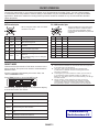
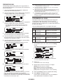
Mode
1 Enter Menu mode and access Menu 000.
External
SP1
External
SP2
A, B
–
–
SP1 only
x
A, B
–
SP2 only
A
–
B
SP1, SP2
x
A
B
A, B
–
–
SP1 only
x
A, B
–
SP2 only
B
–
A
SP1, SP2
x
B
A
None
2 Turn the beep function ON or OFF.
• Even with the beep function turned OFF, the transceiver
will emit a beep tone under the following conditions:
1)When Auto Power Off is activated, the transceiver will
beep 1 minute before the power turns off.
2)After transmitting for the maximum time duration
according to the Time-out Timer, the transceiver will
beep
MODE 2
Band Output
Internal
Speaker
None
MODE 1
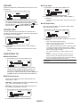
Programmable VFO
Each time you press a key, the beep tone will sound.
If you have left the beep function turned ON, you may
wish to adjust the volume level of the beep.
If you always check frequencies within a certain range,
you can set upper and lower limits for frequencies that are
selectable. For example, if you select 144 MHz for the
lower limit and 145 MHz for the upper limit, the tunable
range will be from 144.000 MHz to 145.995 MHz.
1 Enter Menu mode and access Menu 001.
1 Select your desired VFO frequency.
n Beep Volume
Speaker
Setup
2 Enter Menu mode and access Menu 100.
(Example: E type)
2 Set the beep volume to a level from 1 to 7.
• The default is level 5.
3 Press the Tuning control.
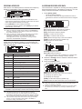
External Speaker Configuration
This transceiver has two speaker jacks for external
speakers, as well as an internal speaker. You can enjoy
a variety of speaker configurations by using one or two
external speakers. Received signals on bands A and B
are output depending on how you want the internal and/or
external speakers to function.
1 Enter Menu mode and access Menu 002.
• The lower frequency limit blinks.
4 Rotate the Tuning control to select your desired lower
frequency limit, then press the Tuning control to set
the selected value.
• The upper frequency limit blinks.
2 Set the speaker mode to MODE 1 or MODE 2.
• Refer to the table below for configurations based on the
mode selected.
5 Rotate the Tuning control to select your desired upper
frequency limit, then press the Tuning control to set
the selected value.
6 Press [ESC] to exit Menu mode.
Note: You cannot program the 100 kHz and subsequent digits. The
exact 100 kHz and subsequent digits of the upper limit depend on the
frequency step size you are using.
OTHER OP-
Changing the Frequency Step Size
Choosing the correct frequency step size is essential in
selecting your exact frequency. The default step size on
the 144 MHz band is 5 kHz (K type) or 12.5 kHz (E, M4
types). The default on the 430/440 MHz band is 25 kHz
(K, E types) or 10 kHz (M4 type) .
1 Press the left or right [BAND SEL] to select band A or
B, then press [VFO].
2 Enter Menu mode and access Menu 101.
2 Set your desired function for the key.
Programmable functions available are: WX CH
(Weather Channel)/ FRQ.BAND (Frequency bands)/
CTRL (Control)/ MONITOR (Monitor)/ VGS (Voice
recorder)/ VOICE (Voice announcement)/ GROUP
UP (Memory group up)/ MENU (Menu mode)/
MUTE (Speaker Mute)/ SHIFT (Shift)/ DUAL (Dual
Mode)/ M>V (Memory to VFO Copy)/ VFO/ MR/
CALL/ MHz/ TONE/ REV (Reverse)/ LOW/ LOCK/
A/B (Band Select A/ Band Select B)/ ENTER/ 1750
(1750 Hz Tone).
Frequency Direct Entry
3 Set the step size to 5.0*, 6.25*, or 8.33 kHz (118 MHz
band only) or to 10.0, 12.5, 15.0*, 20.0, 25.0, 30.0,
50.0, or 100.0 kHz.
* These step sizes are not available for the 1200 MHz band.
Note: Changing between step sizes may correct the displayed
frequency. For example, if
144.995 MHz is displayed with a 5 kHz step size selected, changing
to a 12.5 kHz step size corrects the displayed frequency to 144.9875
MHz.
If the desired operating frequency is far from the current
frequency, using the microphone keypad is the quickest
way to change the frequency. One of the microphone PF
keys must first be programmed as [ENTER],
1 Press the left or right [BAND SEL] to select band A or
B, then press [VFO] or [CALL].
2 Press the key programmed as [ENTER].
• The Direct Frequency Entry display appears.
Programmable Function Keys
n Transceiver Front Panel
There are 2 PF (Programmable Function) keys on the
transceiver front panel: PF1 and PF2. You can assign
your own desired functions to these 2 keys.
1 Enter Menu mode and access Menu 507 (PF1)
and/or Menu 508 (PF2).
2 Set your desired function for the key.
Programmable functions available are: WX CH
(Weather Channel)/ FRQ.BAND (Frequency bands)/
CTRL (Control)/ MONITOR (Monitor)/ VGS (Voice
recorder)/ VOICE (Voice announcement)/ GROUP
UP (Memory group up)/ MENU (Menu mode)/
MUTE (Speaker Mute)/ SHIFT (Shift)/ DUAL (Dual
Mode)/ M>V (Memory to VFO Copy)/ 1750 (1750
Hz Tone).
3 Press the microphone keys ([0] ~ [9]) to enter your
desired frequency.
4 To set the entered frequency, press [ENTER] or
[VFO].
• Pressing [ENTER] before entering all of the digits will set
the remaining digits to 0.
• Pressing [VFO] before entering all of the digits will leave
the remaining digits at their previous values.
• Entering all digits for a frequency will automatically set the
frequency without pressing [ENTER] or [VFO].
• If you need to only change the MHz digit, press the
Tuning control, then enter the new value.
n Microphone Keys
There are 4 microphone PF (Programmable Function)
keys: [PF] (PF1), [MR] (PF2), [VF0] (PF3) and [CALL]
(PF4). You can assign your own desired functions to
these 4 keys.
1 Enter Menu mode and access Menu 509 (MIC.
PF1) and/or Menu 510 (MIC. PF2) and/or Menu 511
(MIC. PF3) and/or Menu 512 (MIC. PF4).
OTHER OP-
AUTOMATIC POWER OFF (APO)
S-Meter Squelch
Automatic Power Off is a background function that
monitors whether or not any operations have been
performed (keys pressed, Tuning control turned, etc.),
and turns the transceiver power OFF if it has not been in
use.
S-meter Squelch causes the squelch to open only when
a signal with the same or greater strength than the Smeter setting is received. This function relieves you from
constantly resetting the squelch when receiving weak
stations that you have no interest in.
1 Enter Menu mode and access Menu 516 (APO).
1 Enter Menu mode and access Menu 105.
2 Set the APO time limit to 30, 60, 90, 120, 180 minutes,
or OFF.
2 Set the S-Meter squelch to ON or OFF.
• After the time limit passes with no operations (default is
OFF), APO turns the transceiver power OFF. However, 1
minute before the power turns OFF, “APO” appears on the
display and blinks, and a warning tone sounds.
Note: If any settings are changed during while APO is ON, the
timer resets. When you stop changing the settings, the timer begins
counting again from 0.
3 To select the desired S-meter setting, rotate the left
(band A) or right (band B) SQL control depending on
which band you have selected.
• The squelch will open only at the level you have selected
(for example, level 9).
n Squelch Hang-up Time
SWITCHING FM/AM MODE
This transceiver is also capable of receiving (not
transmitting) in AM on band A. The default mode on the
118 MHz band is AM while the default on the 144, 220,
300, or 430/440 MHz band is FM.
When using S-meter Squelch, you may want to adjust
the time interval between when the received signals
drop and when the squelch closes.
1 Enter Menu mode and access Menu 106.
1 Enter Menu mode and access Menu 102.
2 Set the hang-up time to 125, 250 or 500 ms, or
OFF.
2 Set the mode to AM, FM, or NFM.
Note: You cannot switch between FM and AM to receive on band B.
Advanced Intercept Point (AIP)
The VHF/UHF band is often crowded in urban areas. AIP
helps eliminate interference and reduce audio distortion
caused by inter modulation. You can use this function
only while operating on the VHF/UHF band.
1 Enter Menu mode and access Menu 103 (VHF.AIP)
and/or Menu 104 (UHF.AIP).
2 Set the AIP to ON or OFF.
OTHER OP-
SPEAKER MUTE
TIME-OUT TIMER (TOT)
While receiving or transmitting on the TX band, you may
not want to hear audio received on the other band. Use
this function to mute the speaker allocated to that band
(not the TX band).
It is sometimes necessary or desirable to restrict a single
transmission to a specific maximum time. You may use
this function to prevent repeater time-outs when accessing
repeaters, or to conserve battery power.
While receiving, press [F], [MUTE] to switch the mute
function ON or OFF.
When TOT times out (default is 10 minutes), the
transceiver generates beeps and automatically returns to
receive mode. To resume transmitting, release and then
press the microphone [PTT] again.
• The
ON.
icon appears on the display when the function is
1 Enter Menu mode and access Menu 109.
n Mute Hang-up Time
When using Speaker Mute, you may want to adjust the
time interval between when you receive a signal and
when the speaker is muted.
1 Enter Menu mode and access Menu 107.
2 Set the timer to 3, 5, or 10 minutes.
Masking a Band
If you have no plans to use band A or B, you can hide the
frequency display on the unused band. This saves power
consumption and makes it simpler to read the information
you need.
1 Turn the transceiver power OFF.
2 Set the hang-up time to 125, 250, 500, 750, or 1000
ms.
2 Press the left or right [BAND SEL] + Power ON.
• The band mask display appears.
Beat Shift
Since the transceiver uses a microprocessor to control
various transceiver functions, the CPU clock oscillator’s
harmonics or image may appear on some spots of the
reception frequencies. In this case, we recommend you
turn the Beat Shift function ON.
1 Enter Menu mode and access Menu 108.
3 Rotate the Tuning control to select the band you want
to hide (or return to normal).
4 Press the Tuning control to set the selected band.
5 Rotate the Tuning control to set the band to select
USE or MASK.
• USE allows you to see and use the band as normal.
MASK hides the band on the display.
2 Set the Beat Shift to ON or OFF.
Selecting an Output Power
It is a good idea to select lower transmit power if
communications is still reliable. This lowers the risk of
interfering with others on the band. When operating from
battery power, you will enjoy more operating time before a
recharge is necessary.
6 Press the Tuning control to set the selection.
7 Press the [ESC] to exit.
Note: You cannot operate the masked band nor use it to receive or
transmit.
Press [LOW] to select high (H) (K, E types only), medium
(M), or low (L) power.
• You can program different power settings for bands A and B.
When the transceiver overheats because of
ambient high temperature or continuous transmission,
the protective circuit may function to lower transmit
output power.
Note:
OTHER OP-
Display Partition Bar
The partition bar that appears between bands A and B can
be removed if desired.
1 Enter Menu mode and access Menu 527.
2 Set the partition bar display to ON or OFF.
Power On Password
If power on password is activated, you cannot operate
the transceiver without first entering your password, after
turning the transceiver power ON. Your password can be
changed using the MCP-2A software, and can contain up
to 6 digits.
1 Enter Menu mode and access Menu 998.
2 Set the power on password to ON or OFF.
• When set to ON, “PASSWD” appears on the display.
3 Enter your password.
4 After entering up to 6 digits, press the Tuning control
to set the password.
Note: Even with Menu 998 turned ON, the power on password
function will not be activated unless you first program a password
using the MCP-2A software.
OTHER OP-
PACKET OPERATION
Connect this transceiver to your personal computer via a Terminal Node Controller (TNC). You can send messages
or commands to far away stations, obtain a variety of information via your local bulletin boards, or enjoy other Packet
applications. Reference material for starting Packet operation should be available at any store that handles Amateur
Radio equipment.
Note: When the distance between the radio antenna and your personal computer is too close, interference may occur.
PC/ COM terminal pins
DATA terminal pins
• The PC terminal is on the rear of the
TX/RX unit and the COM terminal is
on the rear of the Operation panel.
Connect these terminals to a personal
computer.
• When using the built-in TNC, the DATA
terminal is not used.
No.
Name
I/O
Audio signal for packet transmission
q
RTS
O
Request to Send
PKD terminal ground
w
CTS
I
Clear to Send
I
‘L’ is transmitted and the microphone
is muted
e
TXD
O
Transmit Data
r
GND
—
Ground
PR9
O
Detected 9600 (bps) data
t
RXD
I
Receive Data
PR1
O
Detected 1200 (bps) data
y
NC
—
Non Connect
u
NC
—
Non Connect
O
Squelch control signal; Closed: ‘L’,
Open: ‘H’
(The default settings can be changed
in Menu 520)
i
NC
—
Non Connect
No.
Name
I/O
q
PKD
I
w
DE
—
e
PKS
r
t
SQC
y
Function
PACKET MODE
This transceiver has a built-in TNC which conforms to the
AX.25 protocol. This protocol is used for communications
between TNCs.
For the commands supported by the built-in TNC, see
“TNC COMMANDS LIST”.
Press [TNC] 2 times to enter PACKET mode.
Function
Note:
u Not all functions available via conventional TNC’s are supported
by the TNC built in this transceiver.
u The built-in TNC could be automatically reinitiated when
its malfunction is detected; this does not designate that the
transceiver is defective.
u To distinguish your various stations or nodes, you can have up
to 15 Secondary Station Identifiers (SSIDs); ex. W6DJY-1 to
W6DJY-15. You always have to put a dash between your call sign
and SSID number.
u Packet operation, easily affected by transmit and receive
conditions, requires a full-scale S-meter reading for reliable
communication. When the S-meter reads less than maximum
during 9600 bps operation, communication errors are frequent.
The following indicators appear on the transceiver display
to show the current TNC status:
Indicator
PACKET
Status
The TNC is in Packet mode.
STA
Packets to be transmitted still remain in the buffer.
CON
The TNC is in connection with the target station.
MBOD
MAIL
The mailbox in the TNC is being accessed or
connected by the other station.
The mailbox in the TNC holds mail addressed to
you.
12
1200 bps transfer rate selected
96
9600 bps transfer rate selected
Downloaded by
RadioAmateur.EU
PACKET-
Data Band
n PC Port Speed
1 Enter Menu mode and access Menu 519.
Select how data will be transmitted and received on your
transceiver.
1 Enter Menu mode and access Menu 529.
2 Set the PC port speed to 9600, 19200, 38400, or
57600 bps.
2 Set the data band to A-BAND (A band receives and
transmits), B-BAND (B band receives and transmits),
TX:A-BAND RX:B-BAND (A band transmits ( ) and
B band receives ( )), or RX:A-BAND TX:B-BAND (A
band receives ( ) and B band transmits ( )).
• Turning the power ON/OFF will change the port speed
setting.
n SQC Output Setting
You can set the condition for which the SQC output
terminal becomes active.
1 Enter Menu mode and access Menu 520.
COM PORT Speed
You can adjust the speed at which the computer and
transceiver exchange information, when the transceiver is
connected to your computer.
1 Enter Menu mode and access Menu 528.
2 Set the SQC output activation method to one of the
following:
• OFF: SQC output remains inactive.
• BUSY: When a signal is received on the data band,
the SQC output becomes active.
• SQL: While CTCSS/DCS is ON and a matching signal
is received, the SQC output becomes active. While
CTCSS/DCS is OFF, the SQC output becomes active
when a busy signal is received.
• TX: While transmitting, the SQC output becomes
active.
• BUSY.TX: When the conditions of BUSY and TX
(above) are met, the SQC output becomes active.
• SQL.TX: When the conditions of SQL and TX (above)
are met, the SQC output becomes active.
2 Set the COM port speed to 9600, 19200, 38400, or
57600 bps.
• Turning the power ON/OFF will change the port speed
setting.
Using EXTERNAL TNC
n External Data Band
1 Enter Menu mode and access Menu 517.
Note: The activation type (logic) can be changed using the MCP2A software.
2 Set the data band to A-BAND (A band receives
and transmits), B-BAND (B band receives and
transmits), TX:A-BAND RX:B-BAND (A band
transmits and B band receives), or RX:A-BAND TX:
B-BAND (A band receives and B band transmits).
n DATA Terminal Speed
Select 1200 or 9600 bps for the data transfer rate,
depending on TNC.
1200 bps: Transmit data input (PKD) sensitivity is 40
mVp-p, and input impedance is 10 kΩ.
9600 bps: Transmit data input (PKD) sensitivity is 2
Vp-p, and input impedance is 10 kΩ.
1 Enter Menu mode and access Menu 518.
2 Set the data speed to 1200 or 9600 bps.
PACKET-
TNC COMMANDS LIST
The commands supported by the built-in TNC are listed below. You must enter a space between a command name (or
short-form) and a parameter, or between two parameters; ex. AU OFF, BEACON EVERY 18.
Command Name
Short
Parameter
Default
When ON, handles one character using 8 bits in Converse
mode. When OFF, handles one character using 7 bits.
Description
ON/ OFF
ON
8BITCONV
8
AFILTER
AF
Specifies up to 4 control codes to be removed from received
packets when in Converse mode.
$00 ~ $80
$00
AUTOLF
AU
When ON, sends a line feed (LF) to the computer after each
carriage return (CR).
ON/ OFF
ON
AXDELAY
AXD
Specifies the delay time to be added to TXDELAY between
PTT ON and start of transmission. The unit of the parameter
is 10 milliseconds.
0 ~ 120
0
AXHANG
AXH
Specifies the voice repeater hang time. The unit of the
parameter is 100 milliseconds.
0 ~ 250
0
EVERY/ AFTER n
(n = 0 ~ 250)
EVERY 0
BEACON
B
If set to EVERY, sends a beacon packet at intervals of the
specified period (n). If set to AFTER, sends a beacon packet
only once after the specified period (n). The unit of n is
10 seconds.
BTEXT
BT
Specifies the content of the data portion of a beacon packet.
0 ~ 159 characters
−
CALIBRAT
CAL
Sends a space/mark square wave (50/50 ratio). Enter Q to
exit Calibrate mode and restore the Command mode.
−
−
CHECK
CH
Specifies the interval from signal drop-out until execution of
disconnection. The unit of the parameter is 10 seconds.
0 ~ 250
30
CONMODE
CONM
With NOMODE set to OFF, causes the TNC to automatically
enter Converse or Transparent mode when connection is
completed.
C/ T
C
CONNECT
C
Sends a connect request. Call1 is the call sign of the station
to be connected to. Call2 to call9 are call signs of stations to
be digipeated through.
Call1 (VIA call2,
call3, ... call9)
−
CONOK
CONO
When ON, accepts a connect request and returns a UA
packet. When OFF, rejects a connect request and returns a
DM packet.
ON/ OFF
ON
CONSTAMP
CONS
When ON, displays the current date and time when
connection is completed. The correct date and time must be
set using DAYTIME.
ON/ OFF
OFF
CONVERSE
CONV
or K
Causes the TNC to enter Converse mode. Press [Ctrl]+[C]
to restore the Command mode.
−
−
CPACTIME
CP
When ON and in Converse mode, sends a packet at
intervals of the period determined by PACTIME.
ON/ OFF
OFF
CR
CR
When ON, appends a carriage return (CR) to all packets to
be sent.
ON/ OFF
ON
DAYSTAMP
DAYS
When ON, pressing [Ctrl]+[T] in Converse mode causes the
TNC to send date data in addition to time data.
ON/ OFF
OFF
DAYTIME
DA
Sets the current date and time. Enter YYMMDDhhmmss.
Sets 00 as the second if entry of the second is omitted.
−
−
DAYUSA
DAYU
When ON, displays the date like MM/DD/YY. When OFF,
displays the date like DD-MM-YY.
ON/ OFF
ON
DIGIPEAT
DIG
When ON, allows the TNC to function as a digipeater.
ON/ OFF
ON
DISCONNE
D
−
−
Sends a disconnect request.
PACKET-
Command Name
Short
Description
Parameter
Default
DISPLAY
DISP
Causes the TNC to display the current status of all the
commands. You can also specify a class identifier A, C, H, I,
L, M, or T to display the status of only the desired command
class. Enter a space between the command name and a
class identifier; ex. DISPLAY H.
A (ASYNC): RS-232C port parameters
C (CHAR): Special TNC characters
H (HEALTH): Counter parameters
I (ID): ID parameters
L (LINK): TNC-to-TNC link status
M (MONITOR): Monitor parameters
T (TIMING): Timing parameters
−
−
DWAIT
DW
Specifies the interval from no carrier detection until
execution of transmission. The unit of the parameter is 10
milliseconds.
0 ~ 250
30
ECHO
E
When ON, causes the TNC to echo received characters to
the computer.
ON/ OFF
ON
EPATH
EPATH
Specifies digipeater call signs to be added when the
UISSID parameter in a received packet is 10 or 14.
Call1, ... call7
−
EXTCLR
EXTC
Clears the contents of the TNC mailbox.
−
−
FILE
FI
Displays the list of all messages in the TNC mailbox.
−
−
ON/ OFF
OFF
FIRMRNR
FIR
The other station sends a notice (packet) to you if it is
not ready to receive data. When ON, receiving such a
notice causes the TNC to suspend transmission until it
receives a “ready” notice.
FLOVER
FL
Specifies the time deday from when the TNC buffer
becomes full until the TNC buffer is cleared. The unit
of the parameter is 1 minute.
0 ~ 120
0
FLOW
F
When ON, starting key entry causes the computer to
stop displaying received packets.
ON/ OFF
ON
FRACK
FR
Specifies the interval from one transmission until
retry of transmission. The unit of the parameter is 1
second.
0 ~ 15
3
FULLDUP
FU
When ON, allows the TNC to function in full duplex.
When OFF, allows it to use data carrier detect signals
to avoid packet collision.
ON/ OFF
OFF
GBAUD
GB
Selects 4800 or 9600 bps as the transfer rate between
the TNC and the GPS receiver.
2400/ 4800/ 9600
4800
GPSSEND
GPSS
Specifies the content of data to be output to the GPS
receiver; this data is used to program the default
settings on the receiver. The output data is not stored
in memory.
0 ~ 159
characters
−
GPSTEXT
GPST
Specifies the type of a message to be determined by
LTEXT.
0 ~ 6 characters
$PNTS
HBAUD
HB
Selects 1200 or 9600 bps as the transfer rate between
packet stations.
1200/ 9600
1200
HEALLED
HEAL
Determines whether or not normal operations of the
ROM are checked. When ON and if normal operations
are detected, “STA” and “CON” appear and blink
alternately.
ON/ OFF
OFF
HID
HI
When ON, causes the TNC to send an ID packet every
9.5 minutes after digipeating.
ON/ OFF
ON
ID
I
Causes the TNC to send an ID packet.
−
−
KILL
KI
Deletes specific messages in the TNC mailbox.
−
−
PACKET-
Command Name
Short
KISS
KISS
LCSTREAM
LCS
LIST
LI
Description
Parameter
Default
When ON, switching the power OFF then ON causes
the TNC to enter (or exit) KISS mode.
ON/ OFF
OFF
When ON, changes a small letter (a through z) entered
as a stream designator, to a capital letter (A through
Z). A stream designator must be entered immediately
after STREAMSW.
ON/ OFF
ON
−
−
EVERY/ AFTER
n
(n = 0 ~ 250)
EVERY 0
−
−
Call1 (VIA call2,
call3, ... call9)
GPS
0 ~ 159
characters
−
0 ~ 250
0
Displays the list of messages, in the TNC mailbox,
other than those addressed to other stations.
LOCATION
LOC
If set to EVERY, sends GPS data at intervals of the
specified period (n). If set to AFTER, sends GPS data
only once after the specified period (n). The unit of n
is 10 seconds.
LOG
LOG
Displays the list of stations which have connected to
the TNC mailbox.
LPATH
LPA
Specifies call signs to send GPS data. Call1 is the call
sign of the destination. Call2 to call9 are call signs of
stations to be digipeated through.
LTEXT
LT
Specifies the content of a message to be included in
GPS data.
LTMON
LTM
Specifies the interval for displaying a message
determined by LTEXT on the screen; a message
appears like a received beacon packet. The unit of the
parameter is 1 second.
MAIL
MAI
When ON and the TNC mailbox holds a message
addressed to you, outputs “Low” to the MAILLED
terminal.
ON/ OFF
OFF
MAXFRAME
MAX
Specifies the maximum number of packets to be
transmitted at one time.
1~7
4
MBOD
MB
When ON, allows the TNC mailbox to be used.
ON/ OFF
OFF
MCOM
MCOM
When ON, causes the TNC to also monitor control
packets. When OFF, causes it to monitor only
information packets.
ON/ OFF
OFF
MCON
MC
When ON, causes the TNC to monitor other stations
while in connection with the target station.
ON/ OFF
OFF
MINE
MI
Displays the list of messages, in the TNC mailbox,
addressed to you and messages that you sent.
−
−
MONITOR
M
When ON, causes the TNC to monitor packets.
ON/ OFF
ON
MRPT
MR
When ON, causes the TNC to display the entire
digipeat list for monitored packets.
ON/ OFF
ON
MSTAMP
MS
When ON, causes the TNC to display data and time
information for monitored packets.
ON/ OFF
OFF
MYALIAS
MYA
Specifies a call sign for using your station as a
digipeater.
6 characters +
SSID
−
MYCALL
MY
Specifies your call sign.
6 characters +
SSID
−
MYMCALL
MYM
Specifies a call sign to be assigned to your TNC
mailbox.
6 characters +
SSID
−
NEWMODE
NE
When ON, entering a CONNECT command causes
the TNC to immediately enter the other mode.
ON/ OFF
OFF
NO
When ON, does not cause the TNC to automatically
enter the other mode. When OFF, causes it to
automatically enter the other mode as specified by
NEWMODE.
ON/ OFF
OFF
NOMODE
PACKET-
Command Name
Short
Parameter
Default
NPATH
NPATH
Call1, ... call7
−
NTSGRP
NTSGRP
Specifies a group code to be used for making a
$PNTS sentence.
0 ~ 3 characters
−
NTSMRK
NTSMRK
Specifies a mark number to be used for making a
$PNTS sentence.
0 ~ 14
0
NTSMSG
NTSMSG
Specifies a message to be used for making a $PNTS
sentence.
0 ~ 20 characters
−
OVERKILL
OVE
Specifies the number of old messages to be deleted
when the TNC mailbox does not accept a new
message because the memory is full.
0 ~ 255
0
PACLEN
P
Specifies the maximum length of the data portion of a
packet.
0 ~ 255
128
PACTIME
PACT
If set to EVERY, sends a packet at intervals of the
specified period (n). If set to AFTER, sends a packet
only once after the specified period (n). The unit of n
is 100 milliseconds.
EVERY/ AFTER n
(n = 0 ~ 250)
AFTER 10
PERSIST
PE
Specifies a parameter to calculate probability for the
PERSIST/SLOTTIME method.
0 ~ 255
128
PPERSIST
PP
Causes the TNC to use the PERSIST/SLOTTIME
method when ON, or the DWAIT method when OFF.
ON/ OFF
ON
−
−
Specifies one or more message numbers to be read
from the TNC mailbox.
−
−
Restores the default status for all the commands.
−
−
0 ~ 250
5
−
−
0 ~ 15
10
ON/ OFF
ON
RAMTEST
Description
Specifies digipeater call signs to be added when the
UISSID parameter in a received packet is 8 or 12.
RAMTEST Checks the RAM after clearing it.
READ
R
RESET
RESET
RESPTIME
RES
RESTART
RESTART
RETRY
RE
ROUTE
ROU
SENDPAC
SE
Specifies a character which forces a packet to be sent.
0 ~ $7F
$0D
SLOTTIME
SL
Specifies the period of random number generation
intervals for the PERSIST/SLOTTIME method. The
unit of the parameter is 10 milliseconds.
0 ~ 250
3
SPATH
SPATH
Specifies digipeater call signs to be added when the
UISSID parameter in a received packet is 9 or 13.
Call1, ... call7
−
ON/ OFF
ON
Specifies the acknowledgment packet transmission
delay. The unit of the parameter is 100 milliseconds.
Causes the TNC to function as if it is switched OFF
then ON.
Specifies the number of transmission retries.
When ON and receiving a packet forwarded by a
PBBS, leaves the included route information.
STREAMCA
When ON and multiple connections take place,
STREAMC receiving a packet causes the TNC to display the call
sign.
STREAMDB
STREAMD
When ON, causes the TNC to display a stream switch
character included in a received packet.
ON/ OFF
OFF
STREAMSW
STR
Specifies a character to be used for switching streams.
0 ~ $7F
$01
TOUT
TOUT
Specifies the time-out time of the TNC mailbox. When
no packet is received within the specified time, a
disconnect takes place. The unit of the parameter is
10 seconds.
0 ~ 250
30
TRACE
TRAC
When ON, causes the TNC to display all received
packets in their entirety.
ON/ OFF
OFF
TRANS
T
−
−
Causes the TNC to exit Command mode and enter
Transparent mode. To restore Command mode, press
and hold [Ctrl], then press [C] three times.
PACKET-
Command Name
Short
Parameter
Default
TRFLOW
TRF
When ON, causes the TNC to respond to software
flow control from the computer in Transparent mode.
ON/ OFF
OFF
TRIES
TRI
Specifies the number of transmission retries
programmed in the retry counter.
0 ~ 15
0
TXDELAY
TX
Specifies the time delay between PTT ON and start
of transmission. The unit of the parameter is 10
milliseconds.
0 ~ 120
50
TXFLOW
TXF
When ON, allows the TNC to send a software
flow control (XON and XOFF) to the computer in
Transparent mode.
ON/ OFF
OFF
UICHECK
UIC
Does not forward the same UI packet as one received
within the time specified by this command. The unit of
the parameter is 1 second.
0 ~ 250
28
UI
When receiving a UI packet which includes the
parameter specified by this command, replaces the
parameter with the MYCALL parameter and forwards
the packet.
UIDIGI
OFF/
ON Call1, ...
call14
OFF
UIDWAIT
UIDW
When ON and digipeating, causes the TNC to use the
DWAIT and PPERSIST settings.
ON/ OFF
OFF
UIFLOOD
UIF
Specifies how received UI packets, which include
WIDEN-N or TRACEN-N parameters, are processed.
Enter WIDE or TRACE before ID, NOID, or FIRST; ex.
WIDE,FIRST. With ID selected, deletes the relayed
digipeaters and adds the MYCALL parameter. With
NOID, merely decrements N-N; ex. 4-3 to 4-2. With
FIRST, adds the MYCALL parameter only when
serving as the first digipeater.
ID/ NOID/ FIRST
NOID
UISSID
UIS
When ON, causes the TNC to process received UI
packets depending on included destination SSIDs.
ON/ OFF
OFF
UIT
The command name must be followed by up to 5
alphanumeric characters; normally WIDE or TRACE.
Causes the TNC to forward received UI packets which
include WIDEN-N or TRACEN-N parameters.
−
−
Call1 (VIA call2,
call3
CQ
0 ~ 10
1
−
−
ON/ OFF
ON
UITRACE
Description
Specifies call signs to send a packet in Unprotocol
mode. Call1 is the call sign of the destination. Call2
to call9 are call signs of stations to be digipeated
through.
UNPROTO
U
USERS
US
Specifies the number of channels available to connect
requests.
WRITE
W
Allows the TNC mailbox to store your message.
In order to permit only a specific station to read
your message, enter a call sign after the command
name; ex. W JA1YKX. To complete message entry,
press [Enter] (or [Return]), [Ctrl]+[C], then [Enter]
(or [Return]). For a subject, you can enter up to 30
alphanumeric characters.
XFLOW
X
Causes the TNC to perform software flow control when
ON, or hardware flow control when OFF.
PACKET-
APRS®
The Automatic Packet/ Position Reporting System (APRS®) is a software program and registered trademark of Bob
Bruninga, WB4APR. He has made packet communications much more exciting than before. This program allows you to
track mobile stations on a map which you recall on a computer screen. Imagine seeing one mobile station moving on the
map which can be scaled from 0.5 to 2000 miles. You also may be tracked on the computer screen of another station.
Stations to be tracked must transmit beacons at certain intervals. To track other stations, you
usually need a computer running the APRS, a transceiver, and a TNC. To have them track
you, you also need a GPS receiver. It receives signals from the satellites to inform you of your
current geographical position. GPS stands for Global Positioning System. The APRS interprets
the National Marine Electronics Association (NMEA) data strings coming from the GPS receiver.
For further information, consult Internet Web pages relating to the APRS. On one of the Internet
search engines, you may use “APRS” or “Packet Radio” as a key word to find those Web
pages.
This transceiver includes a TNC and a program for dealing with data formats supported by the
APRS. That is, you need no other equipment to transmit, receive, or display APRS packets. You do not need even a GPS receiver if you enter position data manually to transmit. For hams who want to fully enjoy
APRS operations, this transceiver has connection ports with a personal computer and a GPS receiver. This manual,
however, does not describe APRS operations which require a personal computer.
Using this transceiver, you can transmit a station icon, position data, position comment, and status text. With a GPS
receiver, you can also transmit moving speed, moving direction, and altitude data. From any type of station you will
receive information listed below:
Station icon
Position data/ Grid square locator
Position comment
Status text
Distance from station
Direction of station
Depending on the types of stations, you will also receive the following information:
Mobile station
Moving direction/ Moving speed
Fixed station
Transmit power/ Height of antenna/ Antenna gain/ Antenna directivity
Fixed station (using compressed
APRS data format)
Transmit range/ Altitude
Weather station
Wind direction/ Wind speed/ Temperature/ Rainfall in last hour
PACKET PATH AND DIGIPEATER
A packet path specifies how APRS packets should be transferred via
one or more repeaters. A repeater, which is used for packet transfer,
is commonly called a digipeater. This came from a “digital repeater”. A
digipeater is usually located on a mountain top or high building. Unlike
a voice repeater, it operates on a simplex frequency. Each volunteer
who installs a digipeater programs it either as a WIDE or RELAY type.
Generally a WIDE transmits packets over much greater distances
than a RELAY.
In any given area, there should be only one WIDE not to cause extra
traffic or collisions on frequencies. A WIDE is capable of transferring
packets from and to adjacent WIDEs. Like a WIDE, there should be
only one RELAY in a given area; that area is usually much smaller
than a WIDE. So, transmit packets to a RELAY when you cannot
directly reach any WIDE. The RELAY then will transfer the packets to
any accessible WIDE.
On this transceiver, you can edit a packet path using a maximum of
79 alphanumeric characters. The default is“RELAY,WIDE” hat is one
of the common settings. With this setting, packets will be transferred
to a RELAY first, then to a WIDE.
APRS-
WIDE-type
RELAY-type
CONNECTING WITH A GPS RECEIVER OR WEATHER
STATION
5 Press [ESC] to exit Menu mode.
Note:
u When used at room temperature (25°C), the error of the internal
clock in a month is within one minute.
u The internal clock is effective until December 31, 2099.
The GPS jack on this transceiver accepts a 2.5 mm
(1/10") 3-conductor plug. If necessary, use the supplied
cable to modify the cable end of your GPS receiver or
Weather Station.
GPS receiver
n Setting Time
1 Enter Menu mode and access Menu 525.
• The first 2 digits blink.
Weather Station
2 Rotate the Tuning control to enter the current hour,
then press the Tuning control.
To GPS jack
• To set 1 o'clock PM for example, select 13.
• The next 2 digits blink.
3 Rotate the Tuning control to enter the current
minute, then press the Tuning control.
4 Press [ESC] to exit Menu mode.
Shield
(to GND on GPS/ WX)
Red
(to DATA OUT on GPS/ WX)
White
(to DATA IN on GPS/ WX)
n Setting UTC Offset
1 Enter Menu mode and access Menu 526.
2 Rotate the Tuning control to select the appropriate
UTC offset, then press the Tuning control.
• In order to use the connected GPS receiver, access Menu
602 (GPS PORT - INPUT) to select “GPS”, “WEATHER
((Davis) )” or “WEATHER (PeetBros. )”.
• The selectable range is from +12:00 to –12:00 in steps
of 15 minutes.
3 Press [ESC] to exit Menu mode.
ADJUSTING THE INTERNAL CLOCK
This transceiver has a clock to manage information on
when APRS packets are received. Use Menu Set-up to
correct the current time, date, and if necessary the UTC
offset; UTC stands for Universal Time Coordinated.
Note: The battery for the clock backup is built into the unit. When
the power source is connected, the battery begins to charge. It takes
approximately 12 hours to become fully charged.
n Setting Date
1 Enter Menu mode and access Menu 524.
• The first 2 digits blink.
2 Rotate the Tuning control to enter the current
month (K type) or day, then press the Tuning
control.
• The next 2 digits blink.
3 Rotate the Tuning control to enter the current day
(K type) or month, then press the Tuning control.
• The last 2 digits blink.
4 Rotate the Tuning control to enter the current year,
then press the Tuning control.
APRS-
RECEIVING APRS DATA
ACCESSING RECEIVED APRS DATA
Each time a new APRS packet is received, the frequency
display is interrupted to show information as below:
This transceiver is capable of receiving and storing APRS
data received from up to 100 stations in memory. You can
easily recall the information of the desired station.
1 Press [KEY], [LIST].
Position comment (or status text)
• The received APRS packet may include information on an
object such as a hurricane or tornado. In this case, the name
of the object appears instead of a call sign.
• Press [DETAIL] to access further information.
• To restore the frequency display, press [ESC] or just wait for
approximately 10 seconds.
Note:
u When you receive an APRS packet including an “EMERGENCY”
comment, a different format of display from the above will appear
and a different beep will sound.
u When you receive an APRS position packet that you transmitted,
the frequency display is not interrupted. “MY POSITION”
will appear on the display. This could happen when one or
more digipeaters are used. If you receive a message that you
transmitted, “MY MESSAGE” will appear.
If a received packet does not include new (or proper)
APRS data, the frequency display is not interrupted. An
indicator such as “dP” appears depending on the types of
data. See the table.
Indicator
Duplicate position comment
nP
New position data
oP
Other position
>P
Beyond position limit
aM
ACK message
dM
Duplicate message data
nM
New message data
oM
To other stations message data
rM
Rejected Message
dS
Duplicate status text
nS
Q?
1
3 Press the Tuning control.
• The information of the selected station appears.
Packet that cannot be decoded
dD
Duplicated DX cluster data
nD
New DX cluster data
[BACK]: Restores the list of stations.
[MSG]: Allows message entry to the current station.
[←]: Displays the previous page.
[→]: Displays the next page.
[TUNE]: Set the QSY frequency (APRS only).
[CLR]: Deletes the entire information of the current station.
Request for sending information
??
• Press [F].
2 Rotate the Tuning control to select the desired station
using the cursor ( ).
New status
1
[TOP]: Displays the list of the fast 5 stations.
[5↑]: Displays the list of the previous 5 stations.
[5↓]: Displays the list of the next 5 stations.
[ESC]: Restores the frequency display.
[SORT]: To select the sort function
[FILTER]: To select the filter function
[MSG]: Allows message entry to the current station.
[TUNE]: Set the QSY frequency (APRS only).
[CLR]: Deletes the current station.
[POS.RQ]: Request position.
[ALLCLR]: Deletes all stations.
• When you press [ALLCLR], “CLEAR ALL?” appears with
the message. Press the Tuning Control to clear all.
Meaning
dP
• The list of stations appears.
• The numbers beside the call signs indicate the order in
which data is received. The data received last is assigned
1.
The transceiver automatically transmits the appropriate
information in approximately 2 minutes after receiving a request.
Note:
u When data from the 101st station is received, the oldest data in
memory is replaced by that data.
u Each time a new APRS packet is received from the same station,
the old data from that station (in memory) is replaced by new
data.
Note:
u The APRS programs for PCs have entry fields for a position
comment and status text. The data entered to these two fields are
transmitted as separate packets. This transceiver, however, includes
both of a position comment and status text in one packet to transmit.
u This transceiver beeps each time it receives any type of APRS
packet. You may access Menu 624 (AUDIO - RX BEEP) to
change this setting. The default is “ALL”.
APRS-
Display Example
Page 3
Page 1
q: Position data
q: Station icon
w: Status text
e: Call sign
r: Date
t: Time (packet received)
y: Situation
u: Direction of station
i: Distance from station (mile or km)
o: Position comment 1
1
For packets received from Mic-encoder stations including
TM-D710s, TM-D700s and TH-D7s, position comments
are displayed in the fourth line.
(Object)
w: Grid square locator
(Packet path)
q: Call sign
This transceiver is capable of displaying the following
icons as station IDs.
<APRS>
<NAVITRA>
q: Call sign
Page 2
(Mobile station)
Some icons may appear with overlay characters as below
if the received icon data includes them.
The following icons show the directions of stations relative
to your position. For example, “ ” indicates the other
station is located at the northeast relative to your position.
q: Moving direction
w: Moving speed (m: Mile/hour or k: km/hour)
e: Altitude (' :Feet or M: Meter)
(Weather station)
q: Rainfall (" or mm)
w: Air temperature
e: Wind direction
r: Wind velocity (mph: Mile/hour or kph: km/hour)
t: Atmospheric pressure
y: Humidity
(Fix station)
0.0 to 9999 miles (or km) are shown for distances from
other stations. “xxxxmi” (or “xxxxkm”) is shown for
distances over 9999 miles (or km). If you do not change
the position data in Menu 626 (DISPLAY UNIT 1 - SPEED,
DISTANCE) from the default, “----mi” (or “----km”) is
shown.
The default units for distance and temperature differ
depending on market versions; mile/ °F for the U.S.A./
Canada version, and kilometer/ °C for the other market
versions. If necessary, access Menu 626 (DISPLAY UNIT
1 - SPEED, DISTANCE) and/or Menu 626 (DISPLAY
UNIT 1 - TEMPERATURE) to change the setting(s).
Note: Some stations transmit APRS packets through TNCs
connected to GPS receivers. If you receive packets from those
stations, “GOOD” (satellites tracked) or “LAST” (satellites not tracked)
will be shown as the situation, with GLL, GGA, or RMC which
designates $GPGLL, $GPGGA, or $GPRMC format.
q: Transmit power
w: Height of antenna (elevation) (' : Feet or M: Meter)
e: Antenna gain
r: Antenna directivity omni : Omnidirectional
APRS-
SORT FUNCTION
FILTER FUNCTION
This function allows you to sort the station list according to
the call sign, date time, or distance.
This function allows you to select only the specified types
of data from the station list.
1 Display the station list.
1 Display the station list.
2 Press [SORT].
2 Press [FILTER].
• The sort type list appears on the display.
• The filter type list appears on the display.
3 Select a sort type.
3 Select a filter type.
• “SORTING” appears on the display and sorting begins.
• “FILTERING” appears on the display and filtering begins.
CALLSIGN
All call signs are compared and
arranged in ascending order.
DATE/TIME
All received dates and times are
compared and arranged in descending
order, with the last received message
listed first.
DISTANCE
The distance between the other
station and My station when selecting
the sorting method is calculated, then
compared and arranged in ascending
order, with the closest station listed
first.
4 The newly sorted station list appears on the display.
• After sorting, when new station data is received, it is added to
the station list without resorting.
DIGIPEATER
All icons are searched and those for
digipeaters are displayed.
WEATHER
All icons are searched and those for
the weather bureau are displayed.
MOBILE
All icons are searched and those for
mobile bureaus are displayed.
OBJECT
DTI information is verified and only
object bureaus are displayed.
KENWOOD
DTI information is verified and only
Kenwood TH-D7, TM-D700, and TMD710 bureaus are displayed.
NAVITRA
Received data is verified and only
Navitra bureaus are displayed,
starting from $PNTS.
FREQUENCY
(QSY)
The status list is searched and only
bureaus containing frequency (QSY)
information are displayed.
OTHERS
Bureaus other than those listed
above are displayed.
ALL(OFF)
The filtering function is cancelled.
4 The newly filtered station list appears on the display.
• After the filter function is turned ON, received data is added
to the list but will on be displayed if it matches the filter type
selected.
• For example, with the station list displayed and the filter
selection set to “WEATHER”, all bureaus not relating to
weather are no longer displayed. If mobile station data is
received at this time, the new data will also not be displayed
as long as the weather filter is active.
• DTI (Data Type Identifier) is a 1 byte code which shows the
packet data classification.
APRS-
RECEIVING A MESSAGE
ENTERING A MESSAGE
Each time a proper message is received, the frequency
display is interrupted to show information as below:
To transmit a message, first enter the call sign of the
target station. To transmit a bulletin, enter “BLN#” instead;
where # must be 0 to 9 or A to Z. When the length of your
bulletin exceeds 64 digits, you may transmit more than
one packet to send the entire bulletin. Use # to indicate
the sequence of the bulletin portions. For example, enter
“BLN0” (or “BLNA”) to send the first packet, then “BLN1”
(or “BLNB”) to send the second packet.
q: Indicator
w: Call sign (TX)
e: Receive time
r: Message
t: TX/RX date
y: Line number
• The display shows up to 67 characters of the message.
• “ 01” will appear to indicate the number of messages not yet
read.
• The following indicators appear depending on the types of
received messages:
Indicator
1 Press [KEY], [MSG].
2 Press [NEW] or [REPLY].
• The display for entering a call sign appears; the first digit
blinks. (When you press [REPLY], not necessarily)
Meaning
Message addressed to you
B
Bulletin
!
Report by the National Weather Service
Reception acknowledgment (or rejection) to
your message
G
Message group
To restore the frequency display after reading the
message, press the Tuning control “ 01” will disappear. If
you do not read the message at this time, press [ESC]. “
01” will remain on the restored frequency display.
[BACK]: Cancels entry of a call sign.
[←]: Causes the cursor to move backward.
[INS]: Inserts the currently selected character.
[CLR]: Deletes the digit at which the cursor is blinking.
3 Rotate the Tuning control to select the first digit.
• You can enter 0 to 9, A to Z, and –.
4 Press [→].
5 The cursor moves to the next digit.
6 Rotate the Tuning control to complete the setting.
• The display for entering a message appears; the first digit
blinks.
• The number increments if you press [ESC] for newly received
messages. Checking them with the List function causes the
number to decrement. If “01” was shown, both the number
and message icon disappear.
When a duplicate message from the same station
is received, an error beep sounds; however, an
acknowledgment is returned. “dM” and a call sign appear
on the display.
• When a message to other stations is received, “oM” appears.
Note:
u This transceiver allows you to receive a message also when
the SSID does not match. However, it will not return a reception
acknowledgment.
u The dedicated memory is used for storing both incoming and outgoing
messages. Receiving a new message when the memory is full causes
the oldest message to be deleted. A message not yet transmitted 5
times may be unexpectedly deleted. If the oldest message has not
been accessed using the List function when memory is full, a new
message does not replace the oldest message. This transceiver will
return a reject command and display “rM”.
u This transceiver beeps each time it receives any type of APRS packet.
You may access Menu 624 (SOUND-RX BEEP) to change this
setting. The default is “ALL”.
[SPACE]: Inserts a space
• To copy a message, enter message compilation mode,
press [F] to enter function mode, then press [PASTE1],
[PASTE2], [PASTE3], or [PASTE4] to copy the message
that has been set up for each key.
[ALLCLR]: Clears all digits and backs the cursor to the first
digit.
7 Rotate the Tuning control to select the first digit.
• You can enter alphanumeric characters plus special ASCII
characters.
8 Press [→].
• The cursor moves to the next digit.
9 Repeat steps 7 and 8 to enter up to 67 digits.
10 Press the Tuning control to complete the setting.
The keypad on the microphone also is available to enter
alphanumeric characters in steps 3 and 7.
APRS-
ACCESSING RECEIVED APRS MESSAGES
The table below shows the meanings of the symbols to be
shown in step 2.
This transceiver is capable of storing a maximum of 100
messages in memory. You can easily access one of
those.
1 Press [KEY], [MSG].
Not-yet-read
indicator
• The newer message the smaller number assigned; the
latest message is assigned 1.
[POS]: Displays the latest position data of the current station,
if stored in memory.
Sequence
Time (message received)
q Meaning
Message addressed to you
2 Rotate the Tuning control to select the desired
message using the cursor (s).
B
Bulletin
!
Report by the National Weather Service
w RX or TX?
3 Press the Tuning control.
• If you select an incoming message, the following display
appears:
←
Received message (or bulletin)
→
A message (or bulletin) for transmitting
e Status
n1
[BACK]: Restores the list of messages.
[NEW]: Create a new message.
[REPLY]: Responds to the party from whom you received.
Enters into message setting.
[SEND]: Messages in the list that have not been sent are
transmitted.
[POS]: The position data of the transmitting station is
displayed (if the station data is available).
[CLR]: Deletes the current message.
• If you select one of your outgoing messages, the following
display appears:
[BACK]: Restores the list of messages.
[NEW]: Create a new message.
[EDIT]: Responds to the party from whom you received.
Enters into message setting.
[SEND]: All messages which can be transmitted will be sent 1
time.
[RE-TX]: When pressed for a message assigned a period (.),
resets the retry counter to 5 more transmissions.
[CLR]: Cancels further transmissions of the current message.
1
.1
1
“n” indicates the remaining number of times
for transmitting the message (or bulletin).
A message for which a reception
acknowledgment was returned
A message (or bulletin) transmitted
5 times (For a message, a reception
acknowledgment was not returned.)
These indicators appear for outgoing messages (or bulletins).
TRANSMITTING A MESSAGE
When you press [SEND] on the “MESSAGE LIST” display,
the remaining messages on the Message List will be
transmitted.
After entering a message on the message display,
pressing the Tuning Control will cause it to transmit every
minute.
APRS-
BASIC SETTING
n TX delay <TX DELAY>
Enter Menu mode and access Menu 600.
nMy Call Sign <MY CALLSIGN>
SETTING GPS PORT
Enter Menu mode and access Menu 602
Program your call sign using a maximum of 9
alphanumeric characters. You may include SSID
characters in the string. Unless you program a call
sign, you cannot transmit APRS packets.
This function allows you to set a transmission delay
time between transmitting the APRS data and
transmitting a flag code prior to the APRS data. When
the other station has activated their Save Mode, the
selected delay time is increased.
1 Select MY CALLSIGN.
• The display for entering a call sign appears; the first
digit blinks. The default is “NOCALL”.
n Baud Rate <BAUD RATE>
2 Rotate the Tuning control to select the first digit.
• You can enter 0 to 9, A to Z, and –.
3 Press the [→].
• The cursor moves to the next digit.
• It does not correspond to the Gamin-TXT format.
4 Repeat steps 2 and 3 to enter up to 9 digits.
n Input Type <INPUT>
n Beacon Type <BEACON TYPE>
[OFF]: When using the GPS receiver
[GPS]: When not using the GPS receiver
[WEATHER (Davis)]: When using the weather observation
device (Davis).
• Operation verification model (currently July 2007)
Vantage PRO2
[WEATHER (PeetBros. )]: When using the weather
observation device (PeetBros.).
• Operation verification model (currently July 2007)
ULTIMETER® 2100 (Packet mode)
[APRS]: Select to APRS beacon.
[NAVITRA]: Select to NAVITRA beacon.
SETTING INTERNAL TNC
Enter Menu mode and access Menu 601.
n Differential Information Output <OUTPUT>
n Data Band <DATA BAND>
On this transceiver you can select data band for APRS
mode independent of the selection for Packet mode.
Select band A or B as the data band for receiving or
transmitting APRS packets. The default is band A. “ ”
indicates the current data band.
Note: In Menu 601, the selection switches among A-BAND, BBAND, TX:A-BAND RX:B-BAND, and RX:A-BAND TX:B-BAND.
Select TX:A-BAND RX:B-BAND or RX:A-BAND TX:B-BAND if
APRS networks which use two separate frequencies become
available in the future.
n Packet Transfer Rate <DATA SPEED>
The default APRS packet transfer rate set on the builtin TNC is 1200 bps which is the standard among the
current APRS networks. If APRS networks which use
9600 bps transfer rate become available in the future,
select “9600 bps”
n DCD Sense <DCD SENSE>
Set the communication speed of the external GPS or
other equipment that is connected to the GPS terminal.
The speed is set to 4800 bps (NMEA)/ 9600 bps (IPS
format: SONY) when a GPS receiver is connected.
You can also select the method for inhibiting the built-in
TNC from transmitting. Select one of the two methods.
The default is “D or Rxd Band”.
[D or Rxd Band]: The TNC does not transmit when signals
are present on the data band ( ) or RX data band ( )
[Both Band]: The TNC does not transmit when signals are
present on band A or B.
APRS-
When set to ON, can send the differential information
from the GPS terminal to the GPS receiver.
SETTING WAY POINT
PROGRAMMING POSITION DATA
Enter Menu mode and access Menu 603.
Enter Menu mode and access Menu 605.
n Way Point Format <FORMAT>
n Select Position channel
Select the type of Way point Format that is sent.
[NMEA]: The data which is output from the GPS terminal
using the NMEA-0183 "$GPWPL" format.
[MAGELLAN]: The data which is output from the GPS
terminal using the " $PMGNWPL" format.
[KENWOOD]: The data which is output from the GPS
terminal using the " $PKWDWPL" format.
This transceiver has 5 memory channels for storing position
data. Program latitude and longitude data for up to 5 locations
from which you will often transmit APRS packets. You can
also name the 5 memory channels.
n Way Point Name <NAME>
n Latitude Entry <LATITUDE>
n Name Entry <NAME>
You can enter alphanumeric characters plus special ASCII
characters (up to 8 digits).
Select the length of the Way Point Name. The length can be
set as [6-CHAR], [7-CHAR], [8-CHAR] or [9-CHAR].
The north/ south latitude is entered.
n Longitude Entry <LONGITUDE>
n Way Point Output <OUTPUT>
[ALL]: All Way point information is sent.
[LOCAL]: If the position limit is ON, all the data within the
position limit is sent. If the position limit is OFF, all Way point
data is sent.
[FILTERED]: Information that is permitted using the packet
filter is output as Way point information.
The east/ west longitude is entered.
Note: When selecting GPS in Menu 602 (GPS PORT), the position
information where it is set is not used.
SETTING BEACON INFORMATION
Enter Menu mode and access Menu 606.
COM PORT ON/OFF
Enter Menu mode and access Menu 604.
n Speed Information <SPEED>
Select whether or not to transmit speed information when
using APRS data communications.
n Output <OUTPUT>
This function outputs data from the COM port after receiving
packet and TNC command data from the APRS data
communications. Use this function to verify the received data
from the transceiver.
n Altitude Information <ALTITUDE>
Select whether or not to transmit altitude information when
using APRS data communications.
• When the beacon type is “NAVITRA”, this information will
not appear on the display.
n Position Ambiguity <POSITION AMBIGUITY>
There may be cases where you do not know or do not want to
report your precise locations. For position data, you can select
the number of digits not to be included in your packets. Select
1 to 4, or OFF (default). The table shows how the digits are
cleared.
OFF
1-DIGIT
2-DIGIT
35°31.84
35°31.8
35°31.
139°37.42
139°37.4 139°37.
3-DIGIT
4-DIGIT
35°3 .
35° .
139°3 .
39° .
• When the beacon type is “NAVITRA”, this information will
not appear on the display.
APRS-
SELECTING A POSITION COMMENT
n Operation when Receiving a QSY
Enter Menu mode and access Menu 607.
When QSY (frequency) information is received, the station list
appears (list summary and details) with the verified frequency.
Press the Tuning control.
The APRS data which you transmit always includes one
of the 15 predetermined position comments. Select an
appropriate comment depending on your situation.
• The QSY (frequency) is set to the non data band.
• When using 6.5 kHz or 12.5 kHz step values, the display
does not indicate values for 100 Hz and lower.
The selectable comments are listed below:
[Off Duty] [Enroute] [In Service] [Returning] [Committed]
[Special] [PRIORITY] [CUSTOM 0 ~ CUSTOM 6]
[EMERGENCY!]
SETTING PACKET FILTER
Enter Menu mode and access Menu 609.
• If you select “Emergency!”, a confirmation message appears.
Press the Tuning control again.
n Position Limit <POSITION LIMIT>
If APRS is popular in your area, you may receive too many
APRS packets for a short period. If this disturbs your APRS
activities, specify a distance from your location. You will not
receive APRS packets from stations beyond this distance.
Select the range from 10 to 2500 in steps of 10, plus OFF
(default). The unit is mile or kilometer depending on the
selection in Menu 626 (DISPLAY UNIT 1).
STORING STATUS TEXT
Enter Menu mode and access Menu 608.
n Packet Filter Type <TYPE>
The APRS position data is filtered.
• Check the type(s) you want to receive.
• If all types are checked, you will receive all types of data.
Status text is another comment to transmit with position
data. Unlike a position comment, you can make any
desired comment using a maximum of 42 alphanumeric
characters. This transceiver has 5 memory channels for
preprogramming.
Note: Attaching a long comment can double the size and length of the
packet. Transmit a comment only if necessary.
n Text Transmit Frequency <TX RATE>
Select the frequency on which to transmit the status text when
the APRS beacon is transmitted. You can select [OFF], or
[1/1] ~ [1/8] (APRS only).
• 1/X means the status text will be transmitted X number of
times.
n QSY Function
This function imbeds the frequency of the audio channel to the
first character of the status text message.
n Operation when Receiving a QSY
1 Select text setting number 5.
• Frequency information is imbedded to the first 10
characters of the status text message.
2 Enter the status text message.
APRS-10
SELECTING YOUR STATION ICON
[PTT]:
1 Press [KEY], [BCON] to switch the function ON.
Enter Menu mode and access Menu 610.
• “BCON” appears and blinks.
2 Press and hold the microphone [PTT], then speak
into the microphone.
3 Release the microphone [PTT].
• Releasing the switch transmits your APRS packet.
• You cannot retransmit an APRS packet unless the
time selected in <TX INTERVAL > passes. Wait until
“BCON” starts blinking to indicate transmitting is ready.
Select an icon which will be displayed on the monitors
of other stations as your ID. You may select an icon
depending on your current location.
• The following 29 icons are selectable for APRS:
4 To switch the function OFF, press [KEY], [BCON]
again.
[AUTO]:
KENWOOD/ Home/ Portable / Sailboat/ SSTV/ Aircraft/
Boat/ Car/ Motorcycle/ Jeep/ RV/ Truck/ Van/ Truck(18wheeler)/ Digipeater/ GATEway/ WX/ Person/ Triangle/
Fire/ Eyeball/ Police/ DF station/ Mic-E Repeater/ QSO
Repeater/ Big Question Mark/ IRLP/EchoLink/ Speedpost/
Wreck
1 Press [KEY], [BCON] to switch the function ON.
• “BCON” appears.
• Switching the function ON transmits your APRS packet
once. After that, APRS packets are automatically
transmitted at intervals of the period selected in <TX
INTERVAL >.
• The following 15 icons are selectable for NAVITRA:
2 To switch the function OFF, press [KEY], [BCON]
again.
APRS supports approximately 200 icons. It allows users to
select each icon by specifying a combination of two ASCII
codes, for example, ! and /. One is a symbol code, and
the other is a table identification code (either /or \). If you
select “OTHERS”, use the following procedures:
1 Rotate the Tuning control to select a symbol code,
then press the Tuning control.
n TX Interval Time <TX INTERVAL>
You can change the interval for automatically transmitting
APRS packets. Access <TX INTERVAL > and select 0.2, 0.5,
1, 2, 3, 5, 10, 20, or 30 minutes. The default is 3 minutes.
Note:
u With “AUTO” in < METHOD > and Beacon ON, pressing the
Tuning control to complete the setting causes the APRS packet
to be immediately transmitted. After that, APRS packets are
transmitted at intervals of the selected period.
u While signals are present, an APRS packet is not transmitted
after the interval. Approximately 2 seconds after signals drop,
transmitting is executed.
n Decay Algorithm <DECAY ALGORITHM>
2 Rotate the Tuning control to select a table
identification code, then press the Tuning control.
Note: Because the icon code table is occasionally revised, download
the latest icon code table from Mr. Bruninga's Web page (http:// web.
usna.navy.mil/~bruninga/aprs.html). Click on “DOWNLOAD APRS” on
its home page, then download APRSnnn.zip from the FTP directory
where nnn is a 3-digit number. After uncompressing the zip file, you
will find a created README directory. Open and see Symbols.txt
under this directory.
SETTING BEACON TX ALGORITHM
Enter Menu mode and access Menu 611.
This function continuously extends the packet transmission
interval in the case that there is no change of position
information.
• When the set time elapses and transmission is performed
but a busy signal is present, the transceiver does not
transmit. When there is no longer a busy signal, the
transceiver attempts to transmit after 2 seconds.
• While transmitting by pressing the [PTT] switch, beacon
transmission is reserved.
• If My station call sign is not set, My station data will not be
transmitted.
• Depending on this interval, the transmission of the
message will become a 1 minute interval.
• When My station position data changes, the data is
transmitted using an interval time based on the set Initial
Interval or Proportional Pathing. When the position data
does not change, the data is transmitted based on a
Decay Algorithm (1 minute, 2 minutes, 4 minutes, 8
minutes, 16 minutes, 32 minutes, 32 minutes, 32 minutes,
etc.)
n Packet Transmit Method <METHOD>
Select the operation method for transmitting APRS packets.
The table concludes how operations differ depending on the
selection.
[MANUAL]:
Each press of [KEY], [BCON] transmits your APRS packet.
APRS-11
Downloaded by
RadioAmateur.EU
n Propotional Pathing <PROPOTIONAL PATHING>
This function automatically changes the transmit packet path
with the elapsed time.
Operation example for when PROPORTIONAL PATHING =
ON
Transmission interval is 1 minute. (When the DECAY
ALGORITHM = ON, the decay transmission interval takes
precedence.)
The packet path changes with each transmission as shown
below (when the packet path is set as WIDE1-1,WIDE2-2).
[1 minute] : DIRECT
[2 minutes] : WIDE1-1 (1 Hop)
[3 minutes] : DIRECT
[4 minutes] : WIDE1-1, WIDE2-1 (2 Hops)
[5 minutes] : DIRECT
[6 minutes] : WIDE1-1 (1 Hop)
[7 minutes] : DIRECT
[8 minutes] : WIDE1-1, WIDE2-2 (3 Hops)
This is repeated.
When jointly using a Decay Algorithm, if the speed is 1 knots
or slower, a Decay Algorithm pattern is used for transmitting,
but if the speed is 3 knots or faster, it changes to Proportional
Pathing.
Method 2 (Generic Path):
Program RELAY and/or WIDE; ex. “RELAY,WIDE” (or simply
“R,W”). In this example, your APRS packet is transferred to
any RELAY digipeater near your position first, then to any
WIDE digipeater. You can also program more than one WIDE.
If you enter “WIDE,WIDE” for example, your APRS packet will
be transferred to any WIDE near your position first, then to
another WIDE.
Method 3 (WIDEN-N Path):
Program WIDEN-N, where N-N indicates the number of WIDE
digipeaters to be used for relay. If you enter “WIDE3-3” (or
simply W3) for example, your APRS packet will be relayed by
three WIDEs in any direction.
Method 4 (TRACEN-N Path):
The operation is the same as WIDEN-N except that
digipeaters add their call signs to your packet before
forwarding. You may program “TRACE3-3” (or simply T3) for
example.
Method 5 (SSID Path):
Program a single number 1 to 15. You can easily specify the
number of digipeaters that will be used for relay. You can also
specify which directions of digipeaters relative to your position
will be used. Refer to the following table.
PROGRAMMING A PACKET PATH
Enter Menu mode and access Menu 612.
Select the packet path type from [New-N PARADIGM],
[RELAY PARADIGM], [STATE/SECTION/REGION], or
[OTHERS].
When you press [USE], the “ ” indicator appears on the
left side of the packet path type, showing the current used
information.
• [TOTAL HOPS]: You can select 1 to 7.
• [ABBR]: You can enter up to 5 characters for abbreviated
state names, etc.
Number of
digipeaters
Parameter
Direction
1
1
All
2
2
All
3
3
All
4
4
All
5
5
All
6
6
All
7
7
All
8
2 (or more) 1
North
9
2 (or more)
1
South
10
2 (or more)
1
East
11
2 (or more)
1
West
12
Many
2
North
13
Many
2
South
14
Many
2
East
15
Many
2
West
The first digipeater which receives your APRS data specifies
the entire route to the destination before forwarding; often 2
digipeaters are used in total.
2
The digipeater which receives your APRS data specifies
the call sign of the next digipeater before forwarding. This is
repeated until your APRS data reaches the destination.
1
• When selecting [OTHERS], enter a packet path.
• You can enter 0 to 9, A to Z, , (comma), and –.
• Below are five basic methods for editing a packet path.
Methods 3 to 5 are supported only by advanced APRS
networks.
Method 1 (Specific Path):
Program the call signs of one or more digipeaters in the
sequence of transfer relay; ex. “KD6ZZV,KF6RJZ”.
APRS-12
NETWORK
WEATHER STATION DATA OUTPUT
Enter Menu mode and access Menu 613.
Enter Menu mode and access Menu 615.
To transmit the meteorological data, you must set the
unprotocol. Using this setting, you can limit the data that
is received. Use this when you are in a group. Select
either “APRS(APK102)” or “ALTNET”. When selecting
“ALTNET”, enter the ALTNET.
n Transmit <TX>
VOICE ALERT
Enter Menu mode and access Menu 614.
This function alerts you as to whether or not a station is
active when attempting to perform voice communications
with that station.
You can set Voice Alert to “OFF”, “ON”, or “RX ONLY”.
When using this function, you must also set up a CTCSS
frequency.
[ON]: The “VA” icon appears on the display, above the
frequency.
[RX ONLY]: The “VAR” icon appears on the display,
above the display.
This setting determines whether or not to transmit the
meteorological data obtained from the weather observation
device, with the APRS data communication.
n Transmit Interval Time <TX INTERVAL>
Set the interval at which the meteorological data is transmitted
with the APRS data communication.
The interval can be set to 5, 10, or 30 minutes.
• The weather observation device outputs the
meteorological data at a time interval of approximately 5
minutes.
• The following meteorological data is transmitted:
• Rainfall
• Air temperature
• Wind direction
• Wind velocity
• Atmospheric pressure
• Humidity
• This data is transmitted with the APRS standard format
(latitude/longitude and time information).
• You can verify the meteorological data being output by
viewing My station weather observation device icons.
Note:
u When the built-in data band is set to cross band, the Voice Alert
function does not operate.
u Voice alert takes precedence even when TONE, CTCSS and
DCS are set.
u When Voice alert is ON, TONE or CTCSS frequency scan and
DCS code scan will not operate.
u When Voice alert is ON, you cannot perform TONE or CTCSS
frequency selection and DCS code selection.
APRS-13
SETTING AS A DIGIPEATER
n UIFLOOD
Enter Menu mode and access Menu 619.
n DIGIPEAT
Enter Menu mode and access Menu 616.
This transceiver with a built-in TNC may also be used
as a digipeater. As described in “PACKET PATH AND
DIGIPEATER”, a volunteer who installs a digipeater
is supposed to program it either as a RELAY or WIDE
depending on various conditions.
Note: This transceiver is capable of setting up to 4 path segments
(aliases); each path segment must have less than 10 characters.
However, it is common to program either “RELAY” or “WIDE” as
mentioned above.
Specifies how received UI packets, which include WIDEN-N
or TRACEN-N parameters, are processed. Enter WIDE or
TRACE before ID, NOID, or FIRST; ex. WIDE,FIRST. With
ID selected deletes the relayed digipeaters and adds the
MYCALL parameter. Using NOID decrements N-N; ex. 4-3
to 4-2. Using FIRST adds the MYCALL parameter only when
serving as the first digipeater.
• You can enter 0 to 9, A to Z.
n UITRACE
Enter Menu mode and access Menu 620.
n UICHECK
Enter Menu mode and access Menu 617.
Does not forward the same UI packet as one received within
the time specified. The unit of the parameter is 1 second.
• The counterpart of UIDIGI is valid.
n UIDIGI
STORING USER PHRASES
Enter Menu mode and access Menu 618.
Enter Menu mode and access Menu 621.
When receiving a UI packet which includes the parameter
specified, replaces the parameter with the MYCALL
parameter and forwards the packet.
1 Rotate the Tuning control to switch the function ON,
then press the Tuning control.
2 Rotate the Tuning control to select “ALIASES”, then
press the Tuning control.
• The display for entering a path appears; the first digit
blinks.
• You can enter 0 to 9, A to Z, , (comma), and –.
The command name must be followed by up to 5
alphanumeric characters; normally WIDE or TRACE. This
causes the TNC to forward received UI packets which include
WIDEN-N or TRACEN-N parameters.
• You can enter 0 to 9, A to Z.
This function (clipboard image) allows you to paste
phrases into the APRS message compilation mode. You
can create up to 4 phrases each of which can consist of
up to 32 characters.
• The user phrase function can only be used in the message
compilation mode.
• Before a message is copied, the number of letters cannot
be guaranteed. Only the number of letters available will be
copied, the remainder will be truncated.
• To copy a message, enter message compilation mode, press
[F] to enter function mode, then press [PASTE1], [PASTE2],
[PASTE3], or [PASTE4] to copy the message that has been
set up for each key.
• If the user messages [PASTE1], [PASTE2], [PASTE3], and
[PASTE4], are not set up, they cannot be used.
APRS-14
• You can enter 0 to 9, A to Z, , (comma), and –. For messages,
“ ” is also selectable.
• The keypad on the microphone also is available to enter
alphanumeric characters.
• In order to include a message group code in your outgoing
packet, enter a group code in place of a call sign. To include
a bulletin group code, enter it following BLN#; for example,
“BLN#ABC” where ABC is a group code. Use up to 9
characters for a message group code or up to 4 characters for
a bulletin group code.
STORING AUTO MESSAGE REPLY
Enter Menu mode and access Menu 622.
n Auto Answer Reply <REPLY>
While you are driving, for example, you cannot immediately
answer to received messages. On this transceiver, you can
program the message to be automatically returned when a
message is received.
Note: Unlike a message, a bulletin including a group code will be
received by stations who do not program any bulletin group code.
SETTING SOUND
1 Rotate the Tuning control to select “ON”, then press
the Tuning control.
Enter Menu mode and access Menu 624.
2 Rotate the Tuning control to select “TEXT”, then press
the Tuning control.
• The display for entering a message appears; the first digit
blinks.
n RX Beep Type <RX BEEP>
• You can enter alphanumeric characters plus special ASCII
characters.
This transceiver beeps each time it receives any type of
APRS packets for further description, refer to “RECEIVING
APRS DATA”.
Selection
Operation
OFF
The APRS/NAVITRA beep tone does not
sound.
n Reply To Call Sign <REPLY TO>
When there is a message you would like to reply to for
the specific call sign, preset that call sign for automatic
responses.
MESSAGE
ONLY
Beep sounds only when a message is
received at your station address.
MINE
Beep sounds when a message is
received at your station address and
your transmitted data is received by a
digipeater.
PROGRAMMING A message GROUP CODE
ALL NEW
Beep sounds when a message is
received at your station address and new
packet data is received.
ALL
Beep sounds when a message is
received at your station address and
duplicate data or invalid data is received.
Enter Menu mode and access Menu 623.
n Special Call Sound <SPECIAL CALL>
Use a message group code to exchange messages only
among your group members. With one or more message
group codes programmed, you will receive messages
that include the same group code(s), besides messages
addressed to you. If you program one or more bulletin
group codes, you will not receive bulletins addressed
to other specific groups. You can program any desired
code using alphanumeric characters; up to 9 characters
for messages, and up to 4 characters for bulletins. You
can also program up to 6 codes at the same time; each
code must be separated by a comma (,). If you program
3 message group codes, for example, you will receive all
messages that include one of the 3 codes. If you program
3 bulletin group codes, you will reject bulletins addressed
to specific groups which do not use any of the 3 codes.
This function emits a special call sound when data is received
at My station address. Set the call sign of the stations from
which you want to receive special call notifications.
n APRS Voice Announce <APRS VOICE>
When using an optional VGS-1 unit, you may select ON. Each
time you receive a message addressed to you, the transceiver
announces the call sign of the sender. If the initial character of
the message is %, the transceiver announces the subsequent
characters one by one.
APRS-15
SETTING INTERRUPT DISPLAY
SELECTING A NAVITRA GROUP
Enter Menu mode and access Menu 625.
Enter Menu mode and access Menu 628.
n Display Area <DISPLAY AREA>
n Group Mode <GROUP MODE>
Selects the Display area.
[ENTIRE]:
Select to Group mode ON or OFF.
n Enter Group Code <GROUP CODE>
• You can enter 0 to 9, A to Z.
STORING NAVITRA MESSAGE
[HALF]:
Enter Menu mode and access Menu 629.
n Automatic Brightness <AUTO BRIGHTNESS>
You can create up to 5 phrases each of which can consist
of up to 20 characters.
When ON is selected and My station address message is
received, the backlight turns on.
n Change Color <CHANGE COLOR>
When ON is selected and My station address message is
received, the backlight color changes.
SELECTING A DISPLAY UNIT (1)
Enter Menu mode and access Menu 626.
n Speed, Distance <SPEED, DISTANCE>
Select to [mi/h, mile], [km/h, km], or [knots, nm] .
n Altitude, Rainfall <ALTITUDE, RAIN>
Select to [feet/inch] or [m/ mm].
n Temperature <TEMPERATURE>
Select to [°F] or [°C].
SELECTING A DISPLAY UNIT (2)
Enter Menu mode and access Menu 627.
n Latitude longitude <POSITION>
Select to [dd°mm. mm’], or [dd°mm’ ss. s”] .
n Grid Format <GRID FORMAT>
Select to [MAIDENHEAD GRID], [SAR GRID (CONV)], or
[SAR GRID (CELL)] .
APRS-16
PACKET MONITOR DISPLAY
4 Press [F], [DX].
• Each time new DX cluster data is received, a call sign,
frequency, and time are displayed.
• Information of up to 5 DX stations are displayed at the
same time.
• When a duplicate DX cluster data is received, “dD” and a
call sign are displayed.
This transceiver presents Terminal Window mode to
display raw data of received APRS packets. It displays up
to 155 characters per page and holds up to 10 pages.
1 Press [KEY], [P.MON].
• To enter Terminal Window mode.
[TOP]: Displays the list of the fast 5 stations.
[5↑]: Displays the list of the previous 5 stations.
[5↓]: Displays the list of the next 5 stations.
[ESC]: Restores the frequency display..
[TUNE]: Outputs the PCT data.
[CLR]: Deletes the current DX station.
• DX station detailed display mode
2 To access old pages, press [HOLD].
• Rotate the Tuning control or press [↑] or [↓] to change
the page.
• Press [RESUME] to quit the Hold function.
• While using the Hold function, newly received packets will
not be stored in buffer.
• When press [ALLCLR], packet monitor display is cleared.
Note:
u The terminal window is not available for sending a command to
the TNC.
u The terminal window is available in APRS mode (not in Packet
mode).
u The data in buffer is cleared when the transceiver power is turned
OFF.
[ESC]: Restores the frequency display.
[BACK]: Returns to the DX station list
[TUNE]: Outputs the PCT data.
[CLR]: Deletes the current DX station.
n Connecting TM-D710 with the HF Transceiver
• A D-SUB female/male conversion adapter is required.
DX PACKETCLUSTERS MONITOR
DX PacketClusters are networks which consist of nodes
and stations who are interested in DXing and contesting. If
one station finds a DX station on the air, he (or she) sends
a notice to his (or her) node. Then this node passes the
information to all its local stations besides another node.
This transceiver can display received DX information and
hold the latest information on up to 10 DX stations. Use
this function to monitor the latest DX information in your
local area. You cannot send DX information to a node,
using the function.
Node
In order to connect TM-D710 to the HF transceiver,
you need to prepare three cables by yourself. For
the connection between the PC/ COM connectors on
the two transceivers, you may use a commercially
available RS-232-C cross-wired cable.
Node
Node
Station
1 Access Menu 601 (INTERNAL TNC - DATA BAND) to
select band A or B.
• If the common transfer rate in your local PacketCluster
network is 9600 bps, access Menu 601 (INTERNAL TNC
- PACKET SPEED) and select “9600 bps”.
2 Tune to the frequency of the target PacketCluster
node.
3 Press [TNC] to enter APRS mode.
• “APRS” should appear.
APRS-17
HF transceiver
TM-D710
(f)
PG-5G
(m)
COM connector on HF
transceiver
TROUBLESHOOTING
Problem
Packet operation results in no
connects with other stations.
Probable Cause
Corrective Action
1 The squelch is open.
1 Select the correct squelch level so
that the squelch is opened only when
2 You did not correctly set the data length
signals are present.
and parity bit.
2 Use HBAUD command to select the
appropriate transfer rate.
You did not receive any DX cluster
data.
You did not select the APRS mode.
Press [TNC] to enter APRS mode; “APRS”
should appear.
You cannot transmit any APRS
data.
1 Beacon is OFF.
1 Press [KEY], [BCON] to switch Beacon
ON.
2 The squelch is open.
3 The data band is inactive.
4 You did not select APRS mode.
5 You selected Packet mode.
6 You did not correctly program your call
sign.
2 Select the correct squelch level so
that the squelch is opened only when
signals are present.
3 If you have blanked the data band,
press the appropriate [BAND SEL] (1
s) to active it.
4 Press [TNC] to enter APRS mode;
“APRS” should appear.
5 Press [TNC], then [TNC] again;
“APRS” should appear.
6 Use Menu 600 (BASIC SETTING
– CALLSIGN) to correctly program
your call sign.
You did not receive any APRS
packet.
1 You did not correctly set the data length 1 Select Packet mode, send the following
and parity bit.
commands to the TNC, then select
APRS mode: AW 8 [ENTER], PAR 0
2 You did not select the appropriate
[ENTER], then RESTART [ENTER].
packet transfer rate.
2 Use Menu 601(INTERNAL TNC
– DATA SPEED) to select the
appropriate packet transfer rate
(generally 1200 bps).
When using a GPS receiver
with “AUTO” selected in Menu
611 (BEACON TX ALGORITHM
- METHOD), you did not transmit
any position data.
The GPS receiver did not yet start
correct measurement.
With “AUTO” selected, the transceiver
must first receive any NMEA data in
order to transmit your position data.
You cannot activate Visual Scan,
Remote Control (K type), nor
Repeater (K type).
You selected APRS or Packet mode.
Press, [TNC] repeatedly so neither
“APRS” nor “PACKET” is visible.
APRS-18
TRANSCEIVER RESET
There are 4 types of transceiver reset available:
VFO Reset
Use to initialize the VFO and accompanying settings.
PARTIAL (Partial) Reset
Use to initialize all settings other than the Memory channels, the DTMF memory, and the PM channels.
PM Reset
Use to reset only the Programmable Memory channels to their default values.
FULL Reset
Use to initialize all transceiver settings that you have customized. (Date and time are not reset.)
There are 2 ways to perform a reset on the transceiver: by key operation and by accessing Menu mode.
Key Operation
Menu Mode
1 Turn the transceiver power OFF.
1 Enter Menu mode and access Menu 999.
2 Press [F] + Power ON.
3 Rotate the Tuning control and select your desired
reset type: VFO RESET, PARTIAL RESET, PM
RESET, or FULL RESET.
2 Set the reset type to VFO RESET, PARTIAL RESET,
PM RESET, or FULL RESET.
3 Press the Tuning control to set the reset type.
• A confirmation message appears on the display.
4 Press the Tuning control to set the reset type.
• A confirmation message appears on the display.
• Press [BACK] to return to the previous display or [ESC]
to cancel the reset.
• Press [BACK] to return to the previous display or [ESC]
to cancel the reset.
4 Press the Tuning control again to perform the reset.
5 Press the Tuning control again to perform the reset.
Note: When the Channel Display function or Key Lock function is
ON, the transceiver reset cannot be performed.
Note: When in Remote Control or Repeater mode, you cannot reset
the transceiver using the Key Operation method.
RESET-
VGS-1 (OPTIONAL) OPERATION
When using the optional VGS-1 voice guide & storage unit, you gain access to the voice recorder and voice
announcement functions. <The VGS-1 is sold depending upon area.>
Voice Announcements
When changing modes, frequencies, settings, etc., an audio
voice will announce the new information.
Operation
1 Enter Menu mode and access Menu 003.
2 Set the announcement function to MANUAL, AUTO, or
OFF.
• Refer to the tables below for announcements based on
settings.
MANUAL:
A microphone PF key must be programmed as [VOICE] to
use MANUAL voice announcement.
Operation
While in VFO
mode
Announcement
Press [VOICE]:
Operating band frequency
Press [VOICE]:
While in MR mode “Channel” + Channel number +
operating band frequency
While in Call
mode
Press [VOICE]:
“Call channel” + operating band
frequency
While in Menu
mode
Press [VOICE]:
Menu number or setting value
(some selections have no voice
announcement)
Tone frequency
setup
“Tone frequency” + frequency value
CTCSS frequency
setup
“CTCSS frequency” + frequency value
DCS code setup
“DCS” + code value
AUTO:
Announcements are made automatically when changing a
mode/frequency/setting.
Announcement
Press [VFO]
“VFO”
Press [MR]
“MR”
Press [CALL]
“Call”
Press [MENU]
“Menu” + menu number
Press [F]
“Function”
Press [PM]
“PM”
Press [ENT]
“Enter”
“A”/“B” + “Channel” (for MR only) +
Change the
“Call”/channel number + “Channel”
operating band/
(for CALL only) + operating band
turn the power ON
frequency + output power level
Change the
frequency band
New receive frequency
Setting up the PM
Channel number/“Off”
Frequency direct
entry
Entered key number
Memory Direct
Entry mode
Channel number
Press [F], rotate
Tuning control
On stored channel
“Memory in” + channel number +
frequency
On blank channel
Press [F], [M.IN] in
“Memory in” + channel number +
VFO mode
“Blank”
Press [A/B] in
VFO mode
“A”/“B” + frequency + output power
level
Press [F] and then “Menu” + “Mode” + The main Menu
the Tuning control number corresponds to the first digit.
in VFO mode
(For example, “5” is Menu No. 5xx.)
Select Menu
number in
category
“Menu” + menu number
Select setting
value in Menu
mode
Setting value
Clearing a
memory channel
“Memory”+ channel number + “Clear”
Perform a Full
Reset
“Full reset?”
Perform a Partial
Reset
“Partial reset?”
Perform a VFO
Reset
“VFO reset?”
Perform a PM
Reset
“PM reset?”
VGS-
AUTO:
Announcements are made automatically when changing a
mode/frequency/setting.
Operation
Announcement
Press [LOCK]
(to turn the Lock
function ON)
“Lock on”
Press [LOCK]
(to turn the Lock
function OFF)
“Lock off”
Tone frequency
setup
“Tone frequency” + frequency value
CTCSS frequency
setup
“CTCSS frequency” + frequency value
DCS code setup
“DCS” + code value
MHz step
frequency setup
“MHz Step” + frequency value
10 MHz setup
“10” + “MHz setup” + frequency value
Output power
setup
“TX Power” + power level
Receiving APRS
message
Call sign +“Message” + APRS
message
Voice Recorder
The voice recorder provides you with 3 VGS channels for
recording voice memos, along with a single VGS channel
for recording conversations. You can also prepare
automated message responses to received calls.
Each recording can last for up to 30 seconds.
■ Voice Memos
To record a voice memo, for later playback:
1 Press the PF key programmed as [VGS].
2 Press and hold the key for the VGS channel number
you want to store the memo in: [1], [2], or [3].
• A beep will sound and the transceiver will enter
Recording mode.
3 Press and hold the VGS channel number key again
(the same key you pressed in the previous step),
then speak into the microphone to record your
memo.
■ Voice Announcement Language
1 Enter Menu mode and access Menu 004.
• Recording begins as soon as you press the VGS
channel number key, and a timer appears on the
display.
• Pressing the microphone PTT switch at this time will
transmit your message as well as record it. Do not
press the microphone PTT switch if you do not want to
transmit your message.
2 Set the language to ENGLISH or JAPANESE.
■ Voice Announcement Volume
1 Enter Menu mode and access Menu 005.
4 Release the VGS channel number key to end the
recording at any time and store it into the selected
VGS channel.
2 Set the announcement volume level from 1 to 7.
• If the memory becomes full, recording will stop
automatically and store the voice memo to memory.
• “WRITING” appears on the display while the recording
is being stored to memory.
• To turn the volume OFF, turn the announcement
function OFF.
■ Voice Announcement Speed
1 Enter Menu mode and access Menu 006.
2 Set the announcement speed level from 0 to 4.
•
The speed settings are as follows:
0: 0.85 times normal speed
1: Normal speed
2: 1.15 times normal speed
3: 1.30 times normal speed
4: 1.45 times normal speed
VGS-
■Conversation Recorder
■ Playback Repeat
To record a 30 second conversation:
You can set messages to be repeatedly played back.
1 Enter Menu mode and access Menu 009.
1 Enter Menu mode and access Menu 007.
2 Set the Conversation Recorder to ON (or OFF).
2 Set the the Playback Repeat function to ON or OFF.
• The
icon appears on the display when this function
is activated. The
icon does not appear during
playback, in Repeater mode, or in Remote Control
mode.
■ Playback Repeat Interval
If the Playback Repeat function is activated, you can
set a time interval for how often the memo/message is
played back.
1 Enter Menu mode and access Menu 008.
3 Press the PF key programmed as [VGS].
2 Set the interval from 0 to 60 seconds.
4 Press [4] (1s) to store the conversation in VGS
channel 4.
■ Playback
1 Press the PF key programmed as [VGS].
• You can transmit the recording by pressing the [PTT]
switch. (Continue holding the [PTT] switch until the
entire recording is transmitted.)
2 Press the key for the VGS channel number you
want to play back: [1], [2], [3], or [4] (when the
Conversation Recorder is ON).
• The recording saved in the channel you selected is
played back.
• To end playback at any time, press [CLR].
• To exit, press [VGS] again.
• During playback, you can switch to any of recordings
1, 2, 3, or 4 by pressing the appropriate key.
VGS-
CROSS-BAND/ LOCKED-BAND OPERATION (K TYPE MODELS ONLY)
This transceiver is capable of receiving signals on one band and retransmitting signals on the other band. This function
repeats signals originating from one band, using the other band. For example, a signal received on band A (VHF) is
retransmitted on band B (UHF). Similarly, a signal received on band B (UHF) is retransmitted on band A (VHF).
Locked-band Repeater: The transceiver uses the same band to receive or transmit a signal. You can set either the A
band (A-TX) or B band (B-TX) as the transmit band.
Cross-band Repeater: If receiving a signal on the TX band, the transceiver switches the current RX only band to the
TX band. This is useful when joining in a group talk. Participants in a group talk need to set a receive and transmit
frequency on different bands so as not to miss any conversation within the group.
Repeater operation mode
Repeater ID TX
1 Enter Menu mode and access Menu 403.
If necessary, you can set the transceiver to transmit your
call sign every 10 minutes.
1 Enter Menu mode and access Menu 406.
2 Set the Repeater operation mode to CROSS BAND,
LOCKED TX:A-BAND, or LOCKED TX:B-BAND.
2 Set the ID Transmit function to OFF, MORSE, or
VOICE.
3 Turn the transceiver power OFF.
4 Press [TONE] + Power ON.
• The Repeater mode is ON and the
and
icons
blink on the display.
• You are unable to perform any transceiver functions while
in Repeater mode.
• To return to normal operation, turn the transceiver power
OFF, then press [TONE] + Power ON.
Note:
u You cannot activate the Repeater function while in single band
operating mode or Weather Channel mode.
u Activating the Repeater function switches OFF the Automatic
Simplex Checker (ASC).
u The Time-Out Timer is locked at 3 minutes.
u Resetting the transceiver will not cancel the Repeater mode.
• To use VOICE transmission, you must have the VGS-1
option installed. When using the VGS-1 option, the ID
Transmit function will use VGS channel 3 as the call sign .
• When selecting MORSE, the call sign stored in Menu
405 {see below} will be transmitted at 20 wpm (words per
minute).
n Entering your Repeater ID
1 Enter Menu mode and access Menu 405.
2 Enter your call sign.
Repeater TX Hold
If necessary, you can set the transceiver to remain in the
transmit mode for 500 ms after a signal drops.
1 Enter Menu mode and access Menu 404.
2 Set the Repeater Hold function to ON or OFF.
CROSS BAND REP-
WIRELESS OPERATION (K TYPE MODELS ONLY)
If you also have a compatible Kenwood handy transceiver, you may use it as a remote control for this mobile transceiver.
You will control one band on the mobile while sending DTMF tones to the other band from the handheld. This function is
useful, for example, when you want to control the mobile from a location outside your vehicle.
Note:
u As a remote control, you can also use a handy transceiver which does not have a remote control function but a DTMF function. However, you
must manually send DTMF tones for control code strings. Skip steps 1 and 3 in “PREPARATION”.
u The FCC rules permit you to send control codes only on the 440 MHz band.
REPARATION
CONTROL OPERATION
Let us assume band A (VHF) of the mobile transceiver will
be controlled.
While in Remote Control mode, the DTMF keys of the
handheld will function as shown in the table below.
Each time you press the desired key, the handheld
will automatically enter transmit mode and send the
corresponding command to the mobile.
On the handy transceiver:
1 Program a 3-digit secret number.
• For the programming method, see the instruction manual
for the handheld.
2 Select the transmit frequency on the UHF band.
3 Make the handheld enter Remote Control mode.
Note: If using a handheld without a remote control function, manually
send “AXXX#YA#” where “XXX” is a 3-digit secret number and “Y” is
a single-digit control command. If you do not add ”A#” to the end, you
can skip sending “AXXX#” next time; however, the mobile may be
accidentally controlled by other stations.
• For the method, see the instruction manual for the
handheld. If not described, consult your dealer.
On the mobile transceiver:
4 Enter Menu mode and access Menu 522.
Operation
DTMF
Command
Access your mobile via the remote unit
(where *** is your 3-digit secret number)
A *** #
End access of your mobile via the
remote unit
A#
DCS ON
1
Tone ON
2
CTCSS ON
3
DCS OFF (all signalling OFF)
4
Tone OFF (all signalling OFF)
5
CTCSS OFF (all signalling OFF)
6
7 Select band A (VHF) as the TX band or Control band.
Call mode ON
7
8 To cause the mobile to send a control acknowledgment
to the handheld, enter Menu 523 and set it to ON.
VFO mode ON
8
Memory mode ON
9
Transmit power (press to toggle
between High, Medium, and Low)
0
5 Set the ID code to the same secret number you set on
the handy transceiver.
6 Select the receive frequency on band B (UHF).
• Match this frequency with the transmit frequency on the
handheld.
• DTMF tones which represent the secret number will be
used as an acknowledgment.
Frequency (in VFO mode) or Memory
channel (in Memory mode) directy entry
9 Turn the transceiver power OFF.
10Press [REV] + Power ON to enter Remote Control
mode.
• The
and
icons appear on the display.
• To exit Remote Control operation, turn the transceiver
power OFF, then press [REV] + Power ON again.
DCS code (when DCS is ON), Tone
frequency (when Tone is ON), or
CTCSS frequency (when CTCSS is ON)
setup
A XXXXXXX
B XXX
(DCS code)
BA XXX
(Tone/ CTCSS
frequency
Repeater (Cross-band or Locked-band)
ON
C
Repeater OFF
D
Step the frequency or Memory channel
down
Step the frequency or Memory channel
up
WIRELESS OP-
#
WEATHER ALERT (K TYPE MODELS ONLY)
The Weather Alert is available only in the USA and Canada. When activated, this function will check for a received NOAA
1050 Hz tone. When the tone is received, the weather alert tone will sound.
Weather Alert ON/ OFF
1 Enter Menu mode and access Menu 110.
2 Set the Weather Alert to ON or OFF.
• When activated, the
icon appears on the display.
• When a signal is being received, the
icon blinks.
n Weather Channel
Whether or not the Weather Alert is activated, you can
still access the weather channels. The Weather Alert
simply notifies you of activity on the weather channels.
1 Press the key programmed with the WX function.
2 Rotate the Tuning control to select your desired
channel.
Channel
No.
Frequency
(MHz)
Memory
Name
Location
A1
162.550
WX 1
NOAA/
Canada
A2
162.400
WX 2
NOAA/
Canada
A3
162.475
WX 3
NOAA/
Canada
A4
162.425
WX 4
NOAA
A5
162.450
WX 5
NOAA
A6
162.500
WX 6
NOAA
A7
162.525
WX 7
NOAA
A8
161.650
WX 8
Canada
A9
161.775
WX 9
Canada
A10
163.275
WX 10
–
Downloaded by
RadioAmateur.EU
WX-1
SKY COMMAND II (K TYPE MODELS ONLY)
The Sky Command II allows remote control of a TS-2000, TS-2000X, TS-B2000, TS-480HX, TS-480SAT, TS-570D, TS570S, or TS-870S HF transceiver.
You will use one transceiver as a control station called “Commander”. The transceiver connected with the HF transceiver
is called “Transporter”. It will function as an interface between the Commander and the HF transceiver. This system
allows you, for example, to watch for and hunt DX while washing your car, or to operate the HF transceiver while relaxing
in your car, living room, or patio, instead of in your shack.
VH
FF
UH
req
FF
.
req
.
The Commander and Transporter transfer audio and commands as below:
VHF freq.
Audio
Commander
Audio
UHF freq.
Audio >
Control commands >
< Response
Control commands >
< Response
Transporter
(TM-D710/ TM-D700/ TH-D7)
HF transceiver
(TM-D710/ TM-D700/ TH-D7)
CONNECTING THE TRANSPORTER WITH THE HF TRANSCEIVER
In order to connect the transporter to the HF transceiver, you need to prepare three cables by yourself. For the connection
between the PC/ COM connectors on the two transceivers, you may use a commercially available RS-232-C cross-wired
cable (A D-SUB female/male conversion adapter is required.)
TM-D710
HF transceiver
TM-D710
(f)
(m)
MIC
To 3.5 mm (1/8")
speaker jack
COM connector on
HF transceiver
PG-5G
HF transceiver
GND (MIC)
MIC connector on
HF transceiver
TM-D710
HF transceiver
To 3.5 mm (1/8")
speaker jack
GND (MIC)
MIC
To EXT SP jack
GND (MIC)
MIC
MIC connector on
HF transceiver
Note:
u Switch OFF both the Transporter and HF transceiver before making the connection.
u The Transporter automatically transmits its call sign in Morse at regular intervals because of legal requirements; therefore, transmit side tone
must be output from the HF transceiver.
u When the Transporter is too close to the HF transceiver, unwanted feedback may cause malfunction.
u Do not share a regulated power supply between the Transporter and the HF transceiver. Unwanted feedback may cause malfunction.
SKY CMD-
PREPARATION FLOW
Note:
u Unless you program call signs, you cannot select “COMMANDER”
or “TRANSPORTER” using Menu 703.
u On the HF transceiver, select 9600 bps and 1 stop bit (default)
using the Menu Set-up function.
u Adjust the audio level on both the Transporter and HF transceiver
while listening to audio output from the Commander. An
appropriate position of the AF control on the HF transceiver might
be in the range, 8:30 to 9:00.
u To distinguish your various stations or nodes, you can have up
to 15 Secondary Station IDentifiers (SSIDs); ex. W6DJY-1 to
W6DJY-15. You always have to put a dash between your call sign
and SSID number.
The following steps should guide you to a good start of
Sky Command operation. First connect the Transporter to
the HF transceiver.
1 <On the Commander and Transporter> Select the
same VHF and UHF frequencies.
2 <On the Commander> Access Menu 700 to program a
call sign (9 digits max.) for the Commander.
• You may enter your exact call sign; ex. W6DJY.
PROGRAMMING CALL SIGNS
3 <On the Commander> Access Menu 701 to program a
call sign (9 digits max.) for the Transporter.
• This call sign must be different from the one for the
Commander. So you may add SSID characters; ex.
W6DJY-1.
The built-in TNCs of the Commander and Transporter
communicate each other when you send a control
command from the Commander. So you must program
different call signs (9 digits max.) on these transceivers as
the IDs of the TNCs.
Use the following Menu Nos. to program call signs:
On Commander
4 <On the Transporter> Access Menu 700 to program
the same call sign as you entered in step 2.
700
COMMANDER
CALLSIGN
Call sign for Commander
701
TRANSPORTER
CALLSIGN
Call sign for Transporter
On Transporter
5 <On the Transporter> Access Menu 701 to program
the same call sign as you entered in step 3.the same
call sign as you entered in step 2.
6 <On the Commander and Transporter> Access Menu
702 and select the tone frequency.
700
COMMANDER
CALLSIGN
Call sign for Commander
701
TRANSPORTER
CALLSIGN
Call sign for Transporter
• Select the same tone frequency on both transceivers.
1 Access Menu 700 or 701, then press the Tuning
control.
• The callsign entry field appears; the first digit blinks.
7 <On the Commander> Access Menu 703 and select
“COMMANDER”.
• “Push [ 0 ] key to start Commander!!” appears.
2 Rotate the Tuning control to select a character.
• You can enter 0 to 9, A to Z, and –.
3 Press [→].
• The cursor moves to the next digit.
8 <On the Transporter> Access Menu 703 and select
“TRANSPORTER”.
4 Repeat steps 2 and 3 to enter up to 9 digits.
[BACK]: Cancels entry of a call sign.
[<-]: Causes the cursor to move backward.
[INS]: Inserts the currently selected character.
[CLR]: Deletes the digit at which the cursor is blinking.
Now the Commander and Transporter are in Sky Command
mode. For operations in this mode, see “CONTROL
OPERATION”. First switch ON the HF transceiver and press
[SYNC] on the Commander. To exit the Sky Command mode,
access Menu 703 and select “OFF”.
5 Press the Tuning control to complete the setting.
6 Press [ESC] to exit Menu mode.
The keypad on the Microphone also is available to
enter alphanumeric characters in step 2.
SKY CMD-
PROGRAMMING A TONE FREQUENCY
CONTROL OPERATION
On receiving a tone from the Commander, the Transporter
causes the HF transceiver to enter Transmit mode. On
both the Commander and Transporter, access Menu 702
and select the desired, same tone frequency.
When in the Sky Command mode, the Microphone keys
of the Commander will function as below. First switch
ON the HF transceiver and press Microphone [0] on the
Commander.
Each time you press the desired key, the Commander
will automatically enter transmit mode and send the
corresponding control command to the Transporter.
Key
[1] (PWR)
[2] (RX)
[3] (MODE)
Function
Power ON/ OFF
HF frequency receive ON/ OFF
Modulation mode switch
[4] (RIT)
RIT ON/ OFF
[5] (XIT)
XIT ON/ OFF
[6] (CLR)
RIT offset or XIT offset clear
[7] (SPLIT)
Split-frequency ON/ OFF
[8] (M>V)
Transfer from Memory to VFO
[9] (A/B)
In VFO mode: VFO A/ VFO B switch
In Memory Recall mode: no change
[0] (SYNC)
Current settings retrieve (from HF
transceiver)
[A] (MONI)
To monitor the UHF band on the
Commander
[B] (M/V)
VFO/ Memory Recall mode switch
[C] (RX)
XIT/ RIT offset frequency increase
[D] (RX)
XIT/ RIT offset frequency decrease
[ ] 1 (UP)
In LSB, USB, or CW mode: 10 Hz/ 1 kHz
switch
In FM or AM mode: 1 kHz/ 10 kHz switch
In VFO mode: frequency entry ON
[#] 2 (DOWN) In Memory Recall mode: channel number
entry ON
[PTT]
To transmit audio on an HF frequency
“FS” appears when you select 1 kHz step (LSB/ USB/ CW) or 10 kHz
step (FM/ AM).
2
After pressing Mic [#], press Mic [0] to [9] to enter a frequency or
memory channel number.
1
Downloaded by
RadioAmateur.EU
Note: To change the frequency or memory channel on the HF
transceiver, rotate the Tuning control.
SKY CMD-