1
™
Aistin
Firmware User Guide
Version 0.8.0
2013-07-19
TABLE OF CONTENTS
1. INTRODUCTION
4
2. AISTIN PROTOCOL
5
DATA FIELDS AND CHARACTER ALLOCATION
MESSAGE STRUCTURE
PROTOCOL CONFIGURATION OPTIONS
MESSAGE TYPES
COMMENT CHARACTER
5
6
6
7
10
3. SOFTWARE DEVICES
11
REGISTER TYPES
11
MASTER REGISTER SET
12
EXAMPLE USE CASES
INCLUDE TIME STAMP TO DATA MESSAGES
14
14
14
14
ANALOG INPUTS REGISTER SET
15
EXAMPLE USE CASES
READING ANALOG INPUT CHANNELS #0 AND #1 TEN TIMES PER SECOND
16
16
16
VIRTUAL MACHINE REGISTER SET
17
EXAMPLE USE CASES
START UPLOADING A NEW PROGRAM FOR THE VM
18
18
18
18
VIRTUAL MACHINE PROGRAM REGISTER SET
19
EXAMPLE USE CASES
19
19
20
READING REAL-TIME CLOCK
SETTING REAL-TIME CLOCK
READING BATTERY VOLTAGE CHANNEL ONCE PER SECOND
START TO RUN USER’S VM PROGRAM
STOP RUNNING THE PROGRAM
START UPLOADING A NEW PROGRAM
UPLOAD AN EMPTY PROGRAM THAT HAS DEVICE ADDRESS ABH
Aistin Firmware 0.8.0 User Guide
© 2013 iProtoXi – www.iprotoxi.fi
2
VIRTUAL MACHINE "RAM" REGISTER SET
21
EXAMPLE USE CASES
CHANGE RAM AREA’S DEVICE ADDRESS
21
21
21
VIRTUAL MACHINE PROGRAM INSTRUCTION SET
22
SOME EXAMPLE PROGRAMS
HELLOWORLD . AIS
TRAFFICLIGHTS . AIS
25
25
25
WRITE A STRING INTO RAM AREA
Aistin Firmware 0.8.0 User Guide
© 2013 iProtoXi – www.iprotoxi.fi
3
1. INTRODUCTION
iProtoXi Aistin firmware is the software provided with the iProtoXi Micro controller board. It is
designed to support easy use of add-on boards, such as accelerometer sensor and gyro, as well as
temperature and humidity sensors, or the RGB-LED board. To achieve this, firmware has ability to
communicate with outer world using a specifically designed human-readable protocol, called Aistin
Protocol.
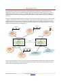
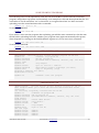
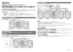
In more complicated configurations there may be several boards connected to a server – Aistin Server
– which in turn may be connected to some clients, such as specific Web pages. Furthermore, there
might be several servers connected together, to enable variety of networking configurations. This
makes possible to network sensors even over the internet. Below is an example picture of a possible
complex networked system configuration.
Sensors
Sensors
Aistin
Controller
#2
I2C-bus
Aistin
Controller
#1
Actuator
I2C-bus
I2C-bus
Aistin
Controller
#3
USB-link
USB-links
Personal Computer
#1
Personal Computer
#2
IP-link
Aistin
Server #1
Aistin
Server #2
IP-link
Aistin
Controller
#4
Bluetooth links
Sensors/Actuators
I2C-bus
Aistin
Controller
#5
Client #1
Plain Terminal
Client #2
Web Page
Aistin protocol makes it possible to access all the networked sensors and actuators from the clients,
with a single unified way. In current implementation, I2C-types of devices are supported, but other
common buses may be implemented later on.
Aistin Firmware 0.8.0 User Guide
© 2013 iProtoXi – www.iprotoxi.fi
4
2. AISTIN PROTOCOL
The Aistin protocol is designed to work using any 7- or 8-bit ascii bearer, and is based on ASCII
characters only. One of its main principles is to be both human- and machine-readable, so it can be
used with just a simple terminal program, such as Windows Hyper Terminal. However, the protocol
has a clear, fixed format to enable other software applications on top of it.
Another important aspect is a small memory footprint, thus instead of having large set of different
command words, there are only few one-letter commands. The needed command divergence is
achieved by using numerical codes, called "addresses". This thinking is derived from the world of
hardware I2C bus, and people familiar with such kind of things will feel the system very pleasing.
Third thing provided by the protocol is "node-addressing". It is possible to address an individual
iProtoXi controller board in a network, even though the board itself doesn't implement a TCP/IP stack.
DATA FIELDS AND CHARACTER ALLOCATION
The protocol is based on data fields that are preceded by a single special character. The characters are
allocated as follows:
>X
Beginning of a message and a message code (X) when it is the first character in a
line, after a carriage return and/or a linefeed
LF
Line feed (ascii code 10), end of a message
CR
Carriage return (ascii code 13), alternative end of a message
@DaRa
Target identifier (targetID): device address (Da), 8-bit register address (Ra)
@DaRaNb
Target identifier: device address (Da), 8-bit register address (Ra), number of bytes
(Nb)
@DaRaraNb
Target identifier: device address (Da), 16-bit register address (Rara), number of
bytes
:D0D1D2..
Data bytes in hexadecimal format, no spaces between bytes
$string
Human readable data – a text string or e.g. a signed 16-bit integer
%time
Time value in decimal, most often in microseconds
~senderID
Identifier string (nodeID) of the sender of a message, maximum length is 12
characters
^receiverID
Identifier string (nodeID) of the receiver of a message, maximum length is 12
characters
'
Comment
In case of 16-bit register address, the byte order is lo-hi: low-order byte comes before the high-order
byte (so called big-endian).
Aistin Firmware 0.8.0 User Guide
© 2013 iProtoXi – www.iprotoxi.fi
5
The protocol aims to be stateless, two-way and symmetric. This means that both sides can send a
message at any time, and they must be prepared to receive a message at any time. Because of
symmetricy, both sides can behave as a "client" and as a "server" – all message types are available for
both sides. There are a few configurable protocol parameters described later.
The overall system is based on idea of "writing" and "reading" data to and from a connected iProtoXi
system. There is also a concept of device address that is used to route messages into the correct place
within the system. The iProtoXi Master Device has a fixed device address, namely hex 80, but there can
be several other "devices" within the same node, each having their unique address. Furher, each
device has one or more registers which are accessed using unique register address.
In case of real I2C devices connected to the main board, they can be accessed "transparently" as
specified in their data sheets. This is a very useful feature.
In outcoming messages receiverID field (^) is a copy of latest incoming message's senderID field (~).
This makes possible to track where an outcoming received message should be forwarded, in case of
multi-client configuration. However, these fields are both optional and may or may not exist. Existence
of senderID in outcoming messages can be configured via Master Register Set.
MESSAGE STRUCTURE
All messages have the following logical structure – the corresponding characters as described in the
previous chapter are shown. All fields may or may not be present. Also, the time field (%) may be
configured to appear before the data.
[ begin-code | message-code | sender | receiver | location | data
>
X
~
^
@
| time | end-code ]
: $
%
(LF/CR)
Where X is one of the following message codes:
R - Read
W - Write
D - Data
S - Scan
A - Acknowledge
Some examples of valid messages could be:
>W@343603:5B23AF
>A@343603
>R@1D2901
>D@1D2901:8D
PROTOCOL CONFIGURATION OPTIONS
Protocol has three configuration bytes that are available through system registers (see Master Register
Set). Configuration options affect also to virtual machine output. Shortly, they are as follows:
Aistin Firmware 0.8.0 User Guide
© 2013 iProtoXi – www.iprotoxi.fi
6
"positiveAck" option controls whether or not acknowledge message is sent as a reply to all received
messages (except the acknowledge message itself, indeed). If it is set ON (value is one), then positive
acknowledge is sent always. The default value is OFF (zero). Note: negative acknowledge i.e. error is
sent always independent of this option.
"messageFields" option is for performance reasons to control if outcoming messages will have
optional targetID field (@) and/or senderID field (~).
"dataTimestamp" option is also for performance reasons to control whether or not outcoming data
messages will have timestamp field or not (%). Default value (zero) is OFF, whereas 01h corresponds
to ON, and the field is positioned before the data. Value 81h is ON, and the field is positioned after the
data. The timestamp precision is fixed to 10-digits, in microseconds.
MESSAGE TYPES
Write – "W"
Write message takes one of the following forms when writing binary data in hexadecimal format:
>W@DaRa:D0D1D2...
8-bit register address
>W@DaRaNb:D0D1D2...
8-bit register address, Nb given
>W@DaRaraNb:D0D1D2... 16-bit register address, Nb is always needed
Where Da is the device address, Ra is the register address, Nb is the number of bytes and D0, D1, D2 ..
are data bytes that will be send into the device Da and written into the register Ra. All numbers are in
two-character hexadecimal format, in other words, a value between 00...FF. Thus, a leading zero is
required if the number is less than hex 10. Spaces are not allowed. If the value of Nb is not zero but
does not match to the given data, an error is returned (negative acknowledge). If Nb is zero, then any
number of data bytes is allowed. Leaving Nb away (first form) equals to setting it to zero. Note that in
case of 16-bit register address, Nb must always be given. Alternative formats for text type of data are
as follows:
>W@DaRa$my text
8-bit register address, Nb is zero
>W@DaRaNb$my text
8-bit register address, Nb given
>W@DaRaraNb$my text
16-bit register address, Nb is always needed
In this case, the data to be written is given as a string and the number of bytes (Nb) is set to either zero
or to match the length of the string. In case of zero, end of string is indicated with linefeed. If protocol
specific characters, linefeed and single quote ('), are included into the string, Nb must be set to
indicate the total length of the string.
Read – "R"
Read message gets one of the following forms:
>R@DaRa
8-bit register address, Nb is zero
>R@DaRaNb
8-bit register address, Nb given
Aistin Firmware 0.8.0 User Guide
© 2013 iProtoXi – www.iprotoxi.fi
7
>R@DaRaraNb
16-bit register address, Nb is always needed
Again, Da and Ra are device and register addresses, whereas Nb is the number of bytes that we want
to read. If Nb is not given or is zero, it indicates that we want to get the Ra in "readable" format. Thus,
the result will be returned as a text instead of hexadecimal byte values. In case of e.g. 16-bit register
the string may be a decimal integer whereas in case of date/time it is a string containing year, month,
day and time. The actual number of bytes that will be read from the register Ra is register-dependent
and may or may not be shown in the responded data message (within the @-field as Nb value).
Read message can be put to repeat itself by giving a time field with a value that sets the period
between reads. For example, the following code reads a register 24h from a device 80h once a second.
Reading stops whenever a new message is send or started.
>R@8024%1000000
Charactes ’m’ and ’s’ can be used to indicate milliseconds and seconds, correspondingly. This avoids
using long microsecond numbers. The previous command can thus be replaced with either of the
following forms:
>R@8024%1000m
>R@8024%1s
Data – "D"
Data message appears normally as a response to a read message as follows:
>D@DaRaNb:D0D1D2..
or
>D@DaRaraNb:D0D1D2..
or
>D@DaRaNb$string
or
>D@DaRaraNb$string
The target ID -field (@) may or may not be included depending on the related configuration option. In
the first case, Nb corresponds to the number of bytes, whereas in the latter case it will be either zero
or the length of the string. Further, if timestamp was requested, then there will be more information
as follows:
>D@DaRaNb%timestamp:D0D1D2..
or
>D@DaRaraNb%timestamp:D0D1D2..
or
>D@DaRaNb%timestamp$string
or
>D@DaRaraNb%timestamp$string
Now, the additional %-character indicates that the following number is a timestamp for the data when
it was read. The value is always in microseconds.
Aistin Firmware 0.8.0 User Guide
© 2013 iProtoXi – www.iprotoxi.fi
8
Scan – "S"
This message is an alias to reading "scan" register from the device 80h. So, the following two messages
do the same thing:
>R@8038ff
or
>S
The 38h is the address of scan register, see register tables at the end of this document. Note that “ff” is
used to indicate we want to read as many bytes as there is available. After a scan command, a
sequence of hexadecimal numbers corresponding to the available device addresses is returned as a
data message, e.g. as follows:
>D@803808:1D203480818D9091
Acknowledge – "A"
If configuration option "positiveAcknowledges" is ON, then the positive acknowledge message takes a
form:
>A@DaRaNb
or
>A@DaRaraNb
Where @DaRaNb has the same contents that was used in the message that caused the
acknowledgment. This field may or may not be present depending on the "includeAddress"
configuration option. Negative acknowledge is sent always and takes a form:
>A@DaRaNb:ER
or
>A@DaRaraNb:ER
Where ER is a non-zero hexadecimal error code. Note that Nb will be the value that was used in the
message that caused this negative acknowledge. It does not tell the number of data bytes in this
message (which is always one, the error code).
Version – "V" or an empty message
A "V" message or an empty message can be used to see some system information, i.e. by giving only
">" character and hitting enter on terminal:
>
Version information is then shown and will be something like the following:
>D@80140C$ipxdevice-01
>D@800805$0.8.0
>D@800C05$1.2.0
>D@800E0C$27EB142B0000
>D@802413$2013-04-05 15.27.48
>D@803806:5D80818D9092
Aistin Firmware 0.8.0 User Guide
Node ID
Software version
Hardware version
Board UID
Real time clock
Scan result: available "devices"
© 2013 iProtoXi – www.iprotoxi.fi
9
COMMENT CHARACTER
Linefeed or carriage return character (ascii 10 or 13) is always used to detect end of message line.
Because messages may be taken from a script file, system also accepts human readable comment
string after the actual message. Comment is separated from the message with a single quote ('), ending
quote is not needed. For example:
>R@802400 'read real time clock as a text
There is a special exception related to this: a comment character can be used to start a message that
contains only a comment, as follows:
'This is a comment only
That kind of message is just ignored by the Aistin system. The lines that do not begin with > or singlequote, will be handled as off-message data and forwarded to a possible connected "raw device", such
as a Bluetooth module.
Note: Because copy-pasting of single-quote from different kind of documents sometimes produces varying
ascii-code, the system interprets all character codes equal to or higher than 80h similar way as the singlequote character.
Aistin Firmware 0.8.0 User Guide
© 2013 iProtoXi – www.iprotoxi.fi
10
3. SOFTWARE DEVICES
In addition to the real I2C devices, the system has a few "software devices" used to access software
features. Those devices have their own register sets described in the following sections. Register set is
a set of parameters that can be read or written by the protocol. There are different types of
parameters, such as bytes, words and strings. It must be noted that words (two bytes) and longs (four
bytes) are in big-endian format, i.e. low-order byte becomes always first.
Each device has its unique device address that is used to address the corresponding register set. In
addition, each register set has a version number to distinguish between possible different versions of
register sets. The version number and total size of the related register set can be read from the first
four bytes of each register set. These four bytes have always fixed, version-independent order, making
possible to deal with different versions.
If register set version byte has its most significant byte set (i.e. the value is equal to or greater than
80h), it means that the register set has additional four control bytes in the beginning. These bytes are
used to control software devices, that are continuously run by the CPU.
REGISTER TYPES
There are the following possible register types:
byte
word
long
string Null-terminating character array
byteff
Hidden byte array – reading ”ff” bytes returns all available data.
One or more of the following operations are possible:
R
Read
W
Write
R$
Readable also as a formatted string, using Nb=00
W$
Writable also as a formatted string, using $ instead of colon (:)
Rff
Arbitrary number of bytes available, can be read using Nb=ff, or maximum amount that is
needed
Reading and writing of several registers with a single command is possible only for the basic register
types: byte, word and long. Even in these cases it might be that all data is not updated, so the safest way is
always to access a single register at a time.
Aistin Firmware 0.8.0 User Guide
© 2013 iProtoXi – www.iprotoxi.fi
11
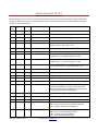
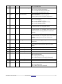
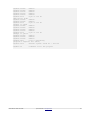
MASTER REGISTER SET
Software Device 80h, Version 81h
Master Register Set is used to control basic features of the iProtoXi Aistin firmware. Most important
things are board's ID, protocol options and access to on-board real time clock. Detailed descriptions
are listed in the table below.
Address
Type
R/W
Name
Values / purpose
00h
byte
R
deviceAddress
80h, identifies this device, "iProtoXi Master"
01h
byte
R
regsVersion
81h, identifies this register set version
02h
word
R
regsSize
0046h, total size of this register set
04h
byte
R
deviceState
State of this device: 0 = stopped, 1 = running
05h
byte
RW
deviceControl
Write to control this device: 01h = reset to
defaults, 02h = stop, 03h = run
06h
byte
RW
debugLevel
Debug messages: 00h = no, 01h = show all
07h
byte
-
(reserved)
Reserved for future purposes
08h
word
R
softwareVersion
Version of iProtoXi Aistin firmware, in
hexadecimal – e.g. 0080h equals to 0.8.0
0Ah
word
R
arduinoVersion
Version of used Arduino build environment, in
hexadecimal – e.g. 0104h equals to 1.0.4
0Ch
word
R
hardwareVersion
Version of iProtoXi Micro board we are running
on, in hexadecimal – e.g. 0120h means 1.2.0
0Eh
6 bytes
RW
boardUID
Six-byte unique board identifier
14h
13 bytes
RW
nodeID
Null-terminated board ("node") identifier string
21h
byte
-
(reserved)
Even-byte alignment
22h
byte
RW
i2cBaseAddress
00h, offset for I2C addresses (not implemented)
23h
byte
RW
virtualI2cBaseAddr
80h, offset for virtual I2C addresses (not impl.)
24h
long
R$W$
datetime
Real time clock, value is in seconds when read as
hexadecimal binary. For text-format date and
time, read zero bytes instead. For setting, send a
string as $YYYY-MM-DD HH.MM.SS
28h
2 bytes
-
(reserved)
Reserved for different type of real time clock
2Ah
long
RW
usCounter
Free running microseconds counter
2Eh
byte
RW
messageBeginChar
">", message begin character (not implemented)
2Fh
byte
RW
positiveAck
Protocol control:
00h = do not send positive acknowledgment
01h = always send acknowledgment
30h
byte
RW
messageFields
Protocol control
00h = do not include optional fields
01h = include location field (@)
02h = include senderID field (~)
Aistin Firmware 0.8.0 User Guide
© 2013 iProtoXi – www.iprotoxi.fi
12
03h = include both
31h
byte
RW
includeTimestamp
Protocol control:
00h = do not include timestamp
01h = include timestamp before data
81h = include timestamp after data
32h
byte
RW
dataEncoding
Protocol control:
00h = encode data as hex, no spaces
(other values are not currently supported)
33h
byte
RW
commChannels
Which channels are used for messaging:
00h = no messaging
02h = serial channel 0 (USB)
04h = serial channel 1 (e.g. Bluetooth)
06h = serial channels 0 and 1
34h
byte
RW
outputChannels
Where to output data messages, see
“commChannels” for accepted values
35h
byte
RW
forwardChannels
Where to forward messages, see
"commChannels" for accepted values. This can be
used to monitor message traffic from another
channel.
36h
byte
RW
nonipxChannels
Where to forward off-message characters, see
“commChannels” for accepted values. This can be
used to communicate with e.g. a Bluetooth
module.
37h
byte
RW
debugChannels
Where to send debug printing – not currently
supported
38h
byteff
Rff
scanForDevices
Read to get list of available device addresses, both
real I2C devices and software devices will be
listed
39h
byte
-
(reserved)
Reserved, even-byte alignment
3Ah
long
-
(reserved)
-
3Eh
long
-
(reserved)
-
42h
byte
RW
powerSaveMode
Operating mode:
00h = no power save
01h = basic power saving
02h = advanced power saving (preliminary)
43h
byte
-
(reserved)
-
44h
byte
R
latestErrorCode
Latest error code
45h
byte
R
detectedConnections
Detected connections:
00h = no connections
02h = USB-connection detected
Aistin Firmware 0.8.0 User Guide
© 2013 iProtoXi – www.iprotoxi.fi
13
EXAMPLE USE CASES
READING REAL-TIME CLOCK
>r@802400
SETTING REAL-TIME CLOCK
>w@8024$2013-07-17 11.20.00
INCLUDE TIME STAMP TO DATA MESSAGES
>w@803101:01
Aistin Firmware 0.8.0 User Guide
© 2013 iProtoXi – www.iprotoxi.fi
14
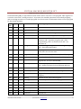
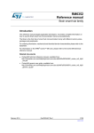
ANALOG INPUTS REGISTER SET
Software Device 81h, Version 01h
This register set is used to read the microcontroller's analog input channels. The index numbers refer
to the ADC-pin numbers shown in Atmega32u4 specification. Note that channels 2 and 3 do not really
exist and most other channels are configured for other purposes in default iProtoXi Micro
configuration. Only channels 0 and 1 are free for user purposes. Channel 5 corresponds to USB voltage
level, channel 6 to battery voltage level and channel 7 measures current consumed by add-on sensor
boards.
Address
Type
R/W
Name
Values / purpose
00h
byte
R
deviceAddress
81h, identifies this device, "Analog Inputs"
01h
byte
R
regsVersion
01h, identifies this register set version
02h
word
R
regsSize
0022h, total size of this register set
04h
byte
R
numAdcChannels
14, number of analog input channels in this register
set. Note! All channels are not supported by the
hardware.
05h
byte
-
(reserved)
Reserved for future use, even-byte alignment
06h
word
R
analogInputs[0]
Analog input value for channel 0
08h
word
R
analogInputs[1]
Analog input value for channel 1
0Ah
word
R
analogInputs[2]
Analog input value for channel 2
0Ch
word
R
analogInputs[3]
Analog input value for channel 3
0Eh
word
R
analogInputs[4]
Analog input value for channel 4
10h
word
R
analogInputs[5]
Analog input value for channel 5
12h
word
R
analogInputs[6]
Analog input value for channel 6
14h
word
R
analogInputs[7]
Analog input value for channel 7
16h
word
R
analogInputs[8]
Analog input value for channel 8
18h
word
R
analogInputs[9]
Analog input value for channel 9
1Ah
word
R
analogInputs[10]
Analog input value for channel 10
1Ch
word
R
analogInputs[11]
Analog input value for channel 11
1Eh
word
R
analogInputs[12]
Analog input value for channel 12
20h
word
R
analogInputs[13]
Analog input value for channel 13
Aistin Firmware 0.8.0 User Guide
© 2013 iProtoXi – www.iprotoxi.fi
15
EXAMPLE USE CASES
READING BATTERY VOLTAGE CHANNEL ONCE PER SECOND
>r@811202%1s
READING ANALOG INPUT CHANNELS #0 AND #1 TEN TIMES PER SECOND
>r@810602%100m
Aistin Firmware 0.8.0 User Guide
© 2013 iProtoXi – www.iprotoxi.fi
16
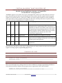
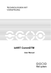
VIRTUAL MACHINE REGISTER SET
Software Device 8Dh, Version 82h
Virtual machine (VM) is a special device that can be used to run user's own program. This register set
is used to control the "virtual processor". In practice, the needed operations are normally stopping
and re-starting execution of a loaded program. See next section for information how to load a program
for the virtual machine.
Address
Type
R/W
Name
Values / purpose
00h
byte
R
deviceAddress
8Dh, identifies this device, "Virtual Machine"
01h
byte
R
regsVersion
82h, identifies this register set version
02h
word
R
regsSize
0031h, total size of this register set
04h
byte
R
deviceState
State of the VM: 0 = stopped, 1 = running
05h
byte
RW
deviceControl
Write to control VM: 01h = reset, 02h = stop, 03h =
continue, 04h = (re)start program, 10h = start
programming, 12h = set autostart off, 13h = set
autostart on
06h
byte
RW
debugLevel
Level of debug messages: 00h = no debug messages,
01h = show debug messages
07h
byte
R
vmControl
VM program autostart bits: 01h = auto-start after
reset, 00h = do not auto-start
08h
word
R
programMemSize
Size of available program memory for a VM program
0Ah
word
R
ramSize
Size of available "RAM" memory for a VM program
0Ch
byte
RW
outputChannels
Channels where VM sends messages, see "Master
Register Set" for more information
0Dh
byte
RW
outputOptions
00h = output plain data
01h = output real time clock on VM start and stop
0Eh
byte
R
condition
VM condition code register
0Fh
byte
-
(reserved)
Reserved for future use, even-byte alignment
10h
word
R
pc
Program Counter, address of the instruction in
progress
12h
word
R
firstTag
Address of first TAG in the program
14h
word
R
prevTag
Address of previous TAG in the program
16h
long
R
vmStartDatetime
Real time when VM started to run program
1Ah
long
R
vmStartTime
Microseconds time when VM started to run program
1Eh
long
-
(internal)
Internal use
22h
long
-
(reserved)
Reserved for future
26h
byte
-
(internal)
Internal use
Aistin Firmware 0.8.0 User Guide
© 2013 iProtoXi – www.iprotoxi.fi
17
27h
byte
-
(reserved)
Reserved for future
28h
byte
-
(internal)
Internal use
29h
byte
-
(reserved)
Reserved for future
2Ah37h
byte
RW
ownerNodeID[13]
Node's ID that currently controls VM (nullterminating string). This is set automatically when
writing to deviceControl byte.
EXAMPLE USE CASES
START TO RUN USER’S VM PROGRAM
>w@8d05:04
STOP RUNNING THE PROGRAM
>w@8d05:02
START UPLOADING A NEW PROGRAM FOR THE VM
>w@8d05:10
Aistin Firmware 0.8.0 User Guide
© 2013 iProtoXi – www.iprotoxi.fi
18
VIRTUAL MACHINE PROGRAM REGISTER SET
Software Device 8Eh = unprogrammed, 90h = programmed; Version 04h
Program register set is used to store virtual machine's application program. All programs must have
specific eight bytes at the beginning, as documented below. Programming is controlled using virtual
machine register set (see Device 8Dh).
Address
Type
R/W
Name
Values / purpose
00h
byte
R
deviceAddress
8Eh when programming or 90h when already
programmed. Identifies this device, "Virtual Machine
Program"
01h
byte
R
regsVersion
04h, identifies this register set version. This is also
used to check program's compatibility with VM.
02h
word
R
regsSize
0100h, total size of this register set. This is maximum
size of VM application, including this header.
04h
byte
RW
programUID[0]
A0h-EFh, device number that the VM application is
implementing, will be copied to VM-RAM
05h
byte
RW
programUID[1]
Register set version that the VM application is
implementing, will be copied to VM-RAM
06h
word
RW
programUID[2-3]
Register set size that the VM application is
implementing, will be copied to VM-RAM
08hFFh
byte
RW
program
The actual VM application's program code.
To send a program, you can use address 08h for each instruction line: the system automatically keeps
track where the next program instruction must be located. In most cases that eliminates the need to
calculate addresses by hand.
EXAMPLE USE CASES
START UPLOADING A NEW PROGRAM
>w@8d05:10
Aistin Firmware 0.8.0 User Guide
© 2013 iProtoXi – www.iprotoxi.fi
19
UPLOAD AN EMPTY PROGRAM THAT HAS DEVICE ADDRESS ABH
>w@8d05:10
>w@8e00:90040001
>w@8e04:ab010000
>w@8e08:00
Aistin Firmware 0.8.0 User Guide
're-program VM
'VM type ID V04 with 0x0100 bytes of room
'program UID: dev. addr, version, reg. set size
'actual program code (00 = no program)
© 2013 iProtoXi – www.iprotoxi.fi
20
VIRTUAL MACHINE "RAM" REGISTER SET
Software Device: 8Fh = unprogrammed, 91h = anonymous application,
92h-9Fh = iProtoXi application, A0h-EFh = user application;
Version 00h-FFh – set by application
"VM-RAM" register set is used to store your own application's data as you wish. However, first four
bytes should always be laid out as described below. They will be directly copied from the program
register set, from the bytes 4-7. The rest of "RAM" area can be used as needed. It is also possible to
store static data, such as constants and strings into this area, and they will resist over power-down,
since data is stored to EEPROM and re-loaded on boot-up.
Address
Type
R/W
Name
Values / purpose
00h
byte
R
deviceAddress
8Fh, 91h-9Fh, A0h-EFh, identifies your device that the
VM application is implementing. The values below
A0h and over EFh are reserved for other purposes. At
the beginning of programming, address is set to 8Fh.
When program is started, default value 91h is used if
the program does not specify any other value
(“anonymous application”).
01h
byte
R
regsVersion
00h-FFh, identifies your register set version
02h
word
R
regsSize
00h-80h, total size of your register set, meaning the
bytes you are providing as an interface to be read and
written by the Aistin protocol
04h7Fh
byte
RW
ram
"RAM" and static data area for free use by your VM
application
Note that bytes 00h-03h are read-only. To change them, you must provide the values via the Program
register set, using register programUID[] (bytes 4-7).
EXAMPLE USE CASES
WRITE A STRING INTO RAM AREA
>w@8d05:10 'begin programming
>w@8f04$My string
CHANGE RAM AREA’S DEVICE ADDRESS
The correct and only way to change ram area’s device address is to begin programming and then to
write the desired device address into program area’s register 04h. This is shown below.
>w@8d05:10 'begin programming
>w@8e04:ab 'set device address we want to provide to ABh
Aistin Firmware 0.8.0 User Guide
© 2013 iProtoXi – www.iprotoxi.fi
21
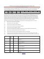
VIRTUAL MACHINE PROGRAM INSTRUCTION SET
For the Device 8Eh, version 04h
Virtual machine is based on assembly-alike instructions, laid out as byte stream with operation codes
and corresponding arguments. The operation code byte (opcode) is divided into following bits:
bit
7
6
5
4
3
Purpose
Op.
modifier
Operand
type
Operand
size
Operation code
2
1
0
Operation code -bits define the operation in case, for example addition or multiplication. In most cases,
Operand size is set zero for byte-sized operations and one for word-sized. The Operand type bit is
mostly set zero if one of the operands is included as an immediate value, and one, if that operand
should be taken from a RAM register, instead. Operation modifier is mostly used to select between
unsigned and signed oprations. The table below lists all available instructions. Note that arithmetic
instructions are currectly always producing saturated results in case of under/overflow.
The supported instructions are described in the table below. Following abreviations are used:
rd
Byte value, destination ram address
rs
Byte value, source ram address
Da
Byte value, destination device address
Ra
Byte value, destination device register address
Nb
Byte value, used as a number of bytes
de
Byte value, message data encoding: use 42h for text, 03h for binary in hexadecimal
b#
Byte value, read as immediate value from code flow
w#
Word value (two bytes), read as immediate value from code flow
jb
Relative one byte jump address with special values 00h = first TAG, ffh= previous TAG
jw
Absolute two byte jump address with special values 0000h = first TAG, ffffh = previous TAG
Mnemonic
Code
[hex]
Operands
Description
readdev8.b
01
rd, Ra
Read a single byte from current device using 8-bit register
address
readdev8.w
21
rd, Ra
Read a word (2 bytes) from current device using 8-bit
register address
readdev8.n
02
rd, Ra, Nb
Read Nb bytes from current device using 8-bit register
address
writedev8.b
03
Ra, b#
Write an immediate byte to current device using 8-bit
register address
writedev8.w
23
Ra, w#
Write an immediate word to current device using 8-bit
register address
writedev8.b
43
Ra, rs
Write a single byte to current device using 8-bit register
address
Aistin Firmware 0.8.0 User Guide
© 2013 iProtoXi – www.iprotoxi.fi
22
writedev8.w
63
Ra, rs
Write a word to current device using 8-bit register address
writedev8.n
04
Ra, rs, Nb
Write Nb bytes to current device using 8-bit register
address
copy.b
05
rd, b#
Copy an immediate byte to rd
copy.w
25
rd, w#
Copy an immediate word to rd
copy.b
45
rd, rs
Copy a byte from rs to rd
copy.w
65
rd, rs
Copy a word from rs to rd
copy.n
06
rd, rs, Nb
(*)
add.b
07
rd, b#
Add an immediate unsigned byte value
add.w
27
rd, w#
Add an immediate unsigned word value
add.b
47
rd, rs
Add unsigned bytes: rd = rd + rs
add.w
67
rd, rs
Add unsigned words: rd = rd + rs
add.sb
87
rd, b#
Add an immediate signed byte value
add.sw
A7
rd, w#
Add an immediate signed word value
add.sb
C7
rd, rs
Add signed bytes: rd = rd + rs
add.sw
E7
rd, rs
Add signed words: rd = rd + rs
sub.b
08
rd, b#
Substract an immediate unsigned byte value
sub.w
28
rd, w#
Substract an immediate unsigned word value
sub.b
48
rd, rs
Substract unsigned bytes: rd = rd – rs
sub.w
68
rd, rs
Substract unsigned words: rd = rd – rs
sub.sb
88
rd, b#
Substract an immediate signed byte value
sub.sw
A8
rd, w#
Substract an immediate signed word value
sub.sb
C8
rd, rs
Substract signed bytes: rd = rd – rs
sub.sw
E8
rd, rs
Substract signed words: rd = rd – rs
send.n
4B
rs, Nb, de
Send Nb bytes from rs to output channels as a D message
sync
0C
w#
Synchronize to microseconds time interval
sync
2C
w#
Synchronize to milliseconds time interval
sync
4C
rs
Synchronize to microseconds time interval
sync
6C
rs
Synchronize to milliseconds time interval
jmp.b
0D
jb
Signed one-byte relative jump
jmp.w
2D
jw
Absolute two-byte jump
cmp.b
0E
rs, b#
Compare unsigned bytes
cmp.w
2E
rs, w#
Compare unsigned words
cmp.sb
8E
rs, b#
Compare signed bytes
cmp.sw
AE
rs, w#
Compare signed words
Aistin Firmware 0.8.0 User Guide
Copy Nb bytes from rs to rd
© 2013 iProtoXi – www.iprotoxi.fi
23
jmpneq
0F
jb
Jump if not equal
jmpeq
2F
jb
Jump if equal
jmpg
4F
jb
Jump if greater
jmpgeq
6F
jb
Jump if greater or equal
jmpl
8F
jb
Jump if less
jmpleq
AF
jb
Jump if less or equal
abs.b
15
rd
Take an absolute value from a signed byte
abs.w
35
rd
Take an absolute value from a signed word
mul.b
17
rd, b#
Multiply with immediate unsigned byte
mul.w
37
rd, w#
Multiply with immediate unsigned word
mul.sb
97
rd, b#
Multiply with immediate signed byte
mul.sw
B7
rd, w#
Multiply with immediate signed word
div.b
18
rd, b#
Divide with immediate unsigned byte
div.w
38
rd, w#
Divide with immediate unsigned word
div.sb
98
rd, b#
Divide with immediate signed byte
div.sw
B8
rd, w#
Divide with immediate signed word
tag
1D
-
Mark a loop TAG for a program to loop later on
setdev
1E
b#
Set current device address (Da)
setnode
9E
rs
Set target nodeID to a null-terminating string stored at rs.
Following special values can also be used:
00h = loopback, local reads/writes (default)
01h = allnodes, reads/writes to all nodes
02h = allclients, reads/writes to all clients
03h = vmowner, reads/writes to current VM owner
(*)
This opcode may be replaced with other function in the future – use only if absolutely necessary.
Aistin Firmware 0.8.0 User Guide
© 2013 iProtoXi – www.iprotoxi.fi
24
SOME EXAMPLE PROGRAMS
The following codes can be uploaded as such into the iProtoXi Micro CPU board from a terminal
program, using either copy-paste or alternatively, save example in a file and then upload that file. It is
convenient to use file extension ".ais" in those files, to recognize them later on. After successful
uploading, start the virtual machine with a command:
>w@8d05:04 'restart VM
To stop, use command:
>w@8d05:02 'stop VM
If you want to auto-start the program after uploading, just add the start command as a last line into
the file before uploading. However, whether your program starts again automatically after powerdown, depends on a setting on device 8Dh (Master register set). To set auto-start, command:
>w@8d05:13 'set auto-start ON
To turn it off, command:
>w@8d05:12 'set auto-start OFF
HELLOWORLD . AIS
'HELLOWORLD – iProtoXi Aistin virtual machine program for VM V04
>w@8d05:10
'command: re-program VM
>w@8e00:90040001
'VM V04 program ID
>w@8e04:91001000
'provided device address, version, reg. set size
'actual code
>w@8e08:1d
'loop begins
>w@8e08:2ce803
'sync at 1000 ms = 3e8h ms
>w@8e08:0b040c42
'send "Hello world!" D-message (12 chars)
>w@8e08:0dff
'jump to beginning (loop)
'program's register set (data)
>w@9104$Hello world!
>w@8d05:04
'command: start the program
TRAFFICLIGHTS . AIS
'TRAFFICLIGHTS – iProtoXi Aistin virtual machine program for VM V04
'This example needs you to have the iProtoXi LED controller board
'installed.
'(c) iProtoXi, originally created 2013-04-19 JNi
>w@8d05:10
'command: re-program VM
>w@8e00:90040001 'VM 04 program ID
>w@8e04:91000600 'provided device address, version, reg. set size
'Code begins
>w@8e08:1e34
'select LEDs device
>w@8e08:030040
'init direct..
>w@8e08:03365b
'..PWM
>w@8e08:1d
'loop begins
>w@8e08:6c04
'sync at r04 ms
'Set red light
>w@8e08:031c00
'LED0-R
>w@8e08:031600
'LED0-G
>w@8e08:031700
'LED0-B
>w@8e08:031d00
'LED1-R
Aistin Firmware 0.8.0 User Guide
© 2013 iProtoXi – www.iprotoxi.fi
25
>w@8e08:031800
'LED1-G
>w@8e08:031900
'LED1-B
>w@8e08:031e10
'LED2-R
>w@8e08:031a00
'LED2-G
>w@8e08:031b00
'LED2-B
>w@8e08:6c04
'sync at r04 ms
'Add yellow light
>w@8e08:031d10
'LED1-R
>w@8e08:031810
'LED1-G
>w@8e08:6c04
'sync at r04 ms
'Change to green
>w@8e08:031610
'LED0-G
>w@8e08:031d00
'LED1-R
>w@8e08:031800
'LED1-G
>w@8e08:031e00
'LED2-R
>w@8e08:6c04
'sync at r04 ms
'Change to yellow
>w@8e08:031600
'LED0-G
>w@8e08:031d10
'LED1-R
>w@8e08:031810
'LED1-G
>w@8e08:0dff
'loop to beginning
'program's register set (data)
>w@9104:0004
'default speed: 0400h ms = 1024 ms
>w@8d05:04
Aistin Firmware 0.8.0 User Guide
'command: start the program
© 2013 iProtoXi – www.iprotoxi.fi
26