1
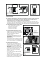
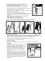
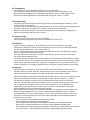
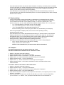
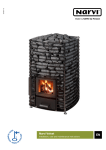
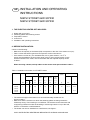
 GB INSTALLATION AND OPERATING
INSTRUCTIONS
NARVI STONET 6kW 907230
NARVI STONET 9kW 907232
1. THE ELECTRIC HEATER SET INCLUDES:
1. Heater with control unit
2. Fastening plates and fastening screws
3. Temperature sensor
4. Control unit
5. Installation and operating instructions
2. BEFORE INSTALLATION:
Check on the following:
– Make sure the capacity of the heater (kW) corresponds to the size of the steam room (m3).
– Table 1 shows the heater types that correspond to various size saunas.
– If the steam room has any non-insulated brick, tile or glass surfaces, 1.5 m3 of
space must be added to the size of the steam room for every square-meter of such
surfaces. Based on the result, choose the heater with the required capacity shown
in table 1.
When choosing a heater, strictly adhere to the steam room space shown in table 1.
Table 1. Installation information for STONET heaters
Stove model
Power
Sauna
Volume
STONET
Minimum safety distances for the stove
Height
On the
sides
At the
front
To the
ceiling
From
the
floor
Quantity of
stones
Connection*)
400 V 3N
Fuses
min
max
min
A **)
B **)
C **)
D **)
kW
m3
m3
cm
cm
cm
cm
cm
kg
mm2
A
6
5
8
190
3
25
100
3
60
5x1,5
3x10
9
8
14
190
5
25
100
3
60
5x2,5
3x16
907230
STONET
907232
**) See figure 1
*) Use a rubber cable, H07RN-F or similar cable
– The minimum height of the steam room and minimal safety clearances are
shown in table 1.
– Make sure that the surface onto which the fastening plates are being screwed is
sufficiently strong. Thin boarding is not sufficient. The surface can be reinforced with
a supporting framework under the boarding or reinforcing boards on top of the wall,
which is connected to a wall framework.
– The heater can also be installed into a wall recess, see figure 1.
ONLY ONE ELECTRIC HEATER MAY BE INSTALLED IN EACH SAUNA ROOM.
10cm
max 30 cm
C min
A min
min 3 cm
B min
A min
A min
Installation of a
stove in an alcove
Figure 1. Minimal safety clearances for the STONET heater.
3. INSTALLATION:
Figure 2.
Kuva 3.2
3.1 Installation instructions for the heater, the temperature sensor and the control unit
-
-
-
Connection of the sauna heater to the power supply may only be carried out by an
authorised electrician in accordance with the valid regulations.
A rubber-sheathed cable of type H07RN-F or similar must be used as the connection cable.
If you want to make use of the temperature control feature, we recommend using a rubber cable
with at least seven wires. The cross-section of the cable and the fuse size are presented in Table 1.
3.11 Connection the power supply cable
-
-
-
Figure 2.1. Connection of circuit board
Lay the sauna heater on the floor,
with its front facing the floor
Remove the bottom plate
Connect the power cable
3.12 Installing the temperature sensor
-
-
-
-
-
Install the sensor in the area lined in Figure 2.
Install the temperature sensor on the wall with
the screws included in the delivery
(2 pcs. Ø 2,9 x 16).
The wiring for the temperature sensor can
be embedded.
Connect the sensor to the circuit plate, as
shown in Fig. 2.1.
Connect the end of the conductor, the one with
no connector in place, to the temperature sensor.
You can cut the conductor to a suitable length.
Socket for the
control unit
Socket for the
temperature sensor
3.13 Installing the control unit
Kuva 5.
The control unit can be installed inside or
outside the steam room. The control unit is
moisture-proof, so it can be installed in the
wash room.
The installation height of the control unit is
a maximum of 90 cm and a minimum of 60 cm
from the side of the heater (see Fig. 3).
Attach the control unit to the wall using
screws (2 x 3.5 *15).
Fastening of the control unit
to the wall. ATTENTION!
Connect the control unit to the circuit plate,
The control unit must
as shown in Fig. 2.1.
not be installed in a wall
The control unit cable is 3.0 metres long.
recess.
A cable of maximum length 10 metres is available Figure 3.
by special order. The excess cable must not be
Ohjauyksikön kiinnitys seinälle
.
inserted into the heater’s connecting box.
HUOM! Käsikapulaa ei
saa
asentaa seinäsyvennykseen.
min. 20cm
Max. 90cm
-
-
-
-
-
-
3.2 Installing the STONET heater and piling the stones
- The heater can be placed on the floor.
- When installing the heater, observe the given safe distances.
- The heater must be attached to the wall, as illustrated in Fig. 4.
24
0
Malli
Model
Stonet 6Kw
Stonet 9Kw
X min mm
80
100
min. 160
225
225
The heater has a two-part front net. The upper part can be removed to
4.8x25 6kplpcs
enable easier piling of the stones in the lower part.
When piling the stones, make sure that the resistors do not get bent and
that the circulation of air is sufficient.
Stones 5-10 cm in diameter are suitable for the heater.
Pile the stones loosely. Stones that are piled too tightly may make
Figure 4. Placement of the
Kuva 2.
the resistors overheat (= shorter life span) and slow down the heating
fastening plate
of the sauna.
The front part of the stone space must, however, be piled as
tightly as possible to cover the resistors.
Tason kannatusruuvien
Ceramic stones cannot be used in this heater!
278
paikat (lattiasta 860 mm)
300
300
70
A STONE CONTAINER THAT IS FILLED TOO SPARSELY MAY BE A FIRE HAZARD!
BEFORE PLUGGING IN THE HEATER, INSPECT THE SAUNA ROOM!
70
-
-
-
-
-
-
X
4.2x9.5 3kp
l
4.2x9.5 3kp
l
4.2x9.5 3kp
l
160
50
4.2x9.5 3kp
l
Figure 4.1
Figure 4.2
Figure 4.3
Figure 4.4
Figure 5.
INSTALLATION ON THE WALL:
- Attach the stove to the fittings of the fastening plate that has been installed on the wall (Fig. 4.1).
- Adjust the height of the adjustable base screws: the stove should rest against the fastening plate (Fig. 4.2).
- With a special frame (available separately), the stove can also be installed in a corner.
- Screw the two fastening screws (Ø 4.2 x 9.5) into the upper frame and one screw
into the fastening plate on the wall (see Figure 4.4).
4. USING THE HEATER
- The heater’s control switch is located at the side, at the lower part of the heater (see Fig. 5).
4.1 Overview
- The heater is switched on and off by toggling the I/O button.
- The SET button is used for setting the following
parameters: Preset timing, power-on time and temperature.
- The setting is carried out using the +/- buttons.
During set-up, an LED flashes to indicate the parameter
being set, with the respective value being displayed
on the screen.
- The settings of the power-on time and the temperature
remain in memory even after a short outage of power. After
a longer outage of power, the times are reset to their default
values. The preset timing will always be reset after use.
- The On/Off LED is illuminated red whenever the heating
elements are turned on; at all other times it is illuminated
green. During the preset time, the On/Off LED is not
illuminated.
On/Off signal light
Preset timing (yellow)
Power-on
time (green)
Temp. (red)
SET
Figure 6.
4.2 Temperature
-
-
-
The temperature of the sauna at the display is shown on the display.
The temperature can be selected at intervals of one degree from the range 60°C-115°C.
When setting the temperature, the temperature saved in the memory, will be displayed first,
and after that will be displayed the temperature that is being set via the +/- buttons.
4.3 Preset timing
-
-
-
-
The yellow LED glows when the preset timing is active. The remaining time to switch-on of the
heater is shown on the display.
Once this time has elapsed, the heater will be switched on, and the On/Off LED will start glowing red.
The preset time will not be saved in the memory, but will reset to zero after use.
When the preset time is being set, the yellow LED flashes. At first, the timing is staggered by
intervals of 30 minutes and after that by an hour.
4.4 Power-on time
- The remaining power-on time is shown on the display.
- At first the timing is staggered by15 minutes and after that by half an hour.
4.5 Power-on
-
-
-
-
-
When the heater is switched on, the temperature of the sauna is showed on the display.
Optionally, the display can be set to show the remaining power-on time or to alternate between
the time and the temperature - see the point Settings.
As soon as the heater reaches the predetermined temperature, the On/Off LED starts glowing
green, and the elements will not be powered.
Once the heater has cooled down to such an extent that the elements will be powered again,
the On/Off LED will again glow red.
The heater remains operational if the power outage lasts less than three minutes. When the power
supply resumes after a power outage of less than three minutes, the heater will resume its operation
from the point where it was before the outage. If the outage lasts longer than three minutes, the
heater is switched off. The settings will always stay in the memory despite duration of the outage.
4.6 Settings
- When the heater is switched on, the power-on time, which will be saved in memory, can be
set within about one minute. After this, the heater goes into its normal operating mode, and any
subsequent settings of the power-on time will only affect the current heating session.
- When the SET button is depressed, the yellow LED will flash, and an array of zeros will be displayed.
- After this, the desired preset time can be selected in steps of 30 min. using the + /- buttons.
- The preset time setting is saved in memory by depressing the SET button a second time.
- After that, the green LED will flash to indicate that you are now able to set the power-on time via
the +/- buttons. The remaining power-on time saved in the memory, will be displayed first.
- After having set the desired power-on time via the +/- buttons, press the SET button again.
Now, the desired power-on time will be saved in memory.
- After the SET button is depressed, the red LED will flash. The temperature setting saved in the
memory, will be displayed first. You can then set the desired temperature via the +/- buttons.
The temperature can be set on the scale 60 °C-115 °C. After this, depress the SET button one
more time to make the heater go into set mode, where the LEDs are continually illuminated to
indicate the current status.
- If the yellow LED is illuminated, the preset timing is active,
and the remaining preset time is being displayed.
- If the On/Off LED is illuminated red, the heater is switched on, the heating elements
are turned on, and the temperature in the sauna is being displayed (default value).
- If the On/Off LED is illuminated green, the heater is switched on, but the elements are switched
off for the moment – the temperature in the sauna is being displayed (default value).
-
-
Once the heater has been set, the set values will remain in memory, and when power is switched
on via the I/O button, the heater will always be warmed up in the same way for the same set period
of time. The preset time, however, will always be zero. If you wish to apply the preset timing
feature, you will always need to activate it separately.
If the SET button is not pressed after the setting, the LED will continue flashing for about one
minute. After this, the heater will automatically return to its normal operating mode, and the settings
will be saved in memory.
4.7 Display settings
- In the normal operation mode of the heater, the parameters to be displayed can be selected
as follows: In the normal operation mode, keep the + and - buttons simultaneously depressed
for more than three seconds. On the display is shown ”d 1”. Now, by pressing the + and buttons one by one, you can switch between three different display modes: ”d 1”,”d 2” and ”d 3”.
-
”d 1”: The temperature of the sauna is shown on the display
-
”d 2”: The remaining power-on time is shown on the display
-
-”d 3”: The temperature of the sauna (the red LED is on)
and the remaining power-on time (the green LED is on) are alternating on the display.
- After having selected the display mode, return to the normal operating mode by
depressing the SET button.
- If the SET button has not been depressed after the setting, ”d” and the number of the selected
display mode will remain on the display for about one more minute. After this, the heater will
automatically return to its normal operating mode, and the settings will be saved in memory.
- The display mode setting will stay in the memory despite outage of the power.
- During pre-timing, is always displayed the remaining preset time.
- After failure, it is possible that one of the following two error codes is being displayed:
-
”E01” : Sensor circuit is open or the sensor is missing.
-
”E02” : The sensor is short-circuited
NOTE! In case of malfunction, the sauna heater will be switched off.
4.8 Examples
The desired temperature in the sauna is about 100 °C and
the heater is desired to be switched on for 2.5 hours at a time.
1. Switch on the power using the I/O button.
2. Depress the SET button -> the yellow LED flashes.
3. Depress the SET button a second time -> the green LED flashes.
4. Depress the + or - button several times until the reading 2:30 is displayed.
5. Depress the SET button -> the red LED flashes.
6. Depress the + or – button several times until the sign P14 is displayed.
7. Depress the SET button -> the heater is switched on and the set values will be saved
for the next time.
You wish to switch on the heater in about three hours
1. Switch on the power using the I/O button.
2. Depress the SET button -> the yellow LED flashes.
3. Depress the + or – button several times until the reading 3:00 is displayed.
4. Depress the SET button -> the green LED flashes.
5. If you want to keep the set power-on time, depress the SET button; to change the power-on time,
use the + or - buttons.
6. After the SET button is depressed, the red LED will flash. If you wish to set the temperature,
you can use the + or - buttons; if not, just depress the SET button to turn the heater on.
The remaining power-on time is only 15 minutes, but you wish to continue enjoying
the sauna for longer than this
1. Depress the SET button -> the green LED flashes, the remaining power-on time
will still be displayed.
2. Select the desired additional time by depressing the + button
3. Depress the SET button -> the red LED flashes.
4. Depress the SET button -> the heater will remain switched on for the time indicated on the display.
5. Note! After the desired period of time has been set, the green LED can be left flashing.
The heater will then automatically return to its normal operating mode within about 1 minute.
The preset time has not run out yet, but you wish to switch on the sauna heater immediately.
1. Depress the SET button -> the yellow LED flashes, and the remaining power-on time
will be displayed.
2. Depress the + or - button as many times as is necessary to decrease the display reading to zero.
-> the heater is switched on and the On/Off LED in the top left corner glows red.
During the preset time it will not be illuminated at all.
3. Depress the SET button -> the green LED flashes.
4. Depress the SET button -> the red LED flashes.
5. Depress the SET button -> the heater remains switched on normally for the time
indicated by the display.
5. TECHNICAL SPECIFICATIONS
Technical specifications
• Temperature range • Preset timing • Power-on time 60 ºC–115 ºC
max. 24 h
max. 4 h
5.2 Upper card
•
•
enclosure class
IPX4
the control unit can be
installed either in the sauna
or in the dressing room
5.3 Lower card
•
•
•
•
•
•
voltage
amperage
heater capacity
protection class
overheating protection
fuse
230 V 3N 50 Hz
16 A
max. 10.5 kW
IPX4
144 ºC
50 mA
6. AIR EXCHANGE FOR THE STEAM ROOM:
- The air exchange in the steam room must be as efficient as possible, in order to
guarantee sufficient oxygen content and availability of fresh air.
-
-
-
-
The fresh air is directed through a ca. 100-mm diameter duct preferably directly
from the outside to above the heater.
There must be a space of at least 1,000 mm between the temperature sensor and
the fresh air duct or 500 mm if the duct end can be turned.
The fresh air can also be directed close to the heater; to the side and underneath.
It is important to introduce fresh air, so that the air mixes with the air and the steam.
-
-
-
The exiting air should be exhausted as far as possible from the incoming air.
The air exhaust valve may be located under the sauna benches.
The exiting air may be directed out of the steam room through the washroom,
for instance under the door. There must be an approximately 100-150-wide slit
between the door and the floor.
7. CONSTRUCTION OF THE STEAM ROOM:
- The steam room must be well insulated, especially the ceiling, through which most of the steam
escapes. Because of the humidity, it is recommended the insulation be covered with a moisture
resistant material, for instance aluminum foil. Wood must always be used to panel the walls.
8. PROTECTIVE BARRIER:
- A protective barrier may be built around the heater if necessary. In this case, you should
definitely adhere to the minimum clearances from structures made of flammable materials.
9. IMPORTANT ADDITIONAL INSTRUCTIONS:
-
-
-
-
-
-
-
You should be careful in the vicinity of the hot heater, because the stones and
metal parts of the heater may cause burns.
Only a small amount of water should be thrown onto the heater stones, because
the steaming water is scalding hot.
This equipment is not to be used by children or people whose physical and
psychological traits, mental functions, lack of experience or knowledge may hinder
the safe operation of the equipment, if the person who is responsible for safety
cannot supervise them or instruct them in the use of the equipment.
Children may not be left unsupervised and they should be supervised to make sure
they do not play with the equipment.
Always inspect the steam room before plugging in the heater.
The improperly filed stone container is a fire hazard.
Covering the stove will cause a fire hazard.
When measuring the insulation barrier of the heater, some leakage may occur, which is
caused by the humidity that has seeped into the insulation material during transport
or warehousing. The moisture will evaporate after the heater is heated a few times.
Do not connect the power supply for the electric heater through a fault current protection!
10. CONNECTION SCHEME:
Overheating
protection
Display
X1-2
X1-3
X1-4
2
Blue
Orange
3
Control unit
4
A1
Disp.
J8
A2
NTC
B1
L1
L1
B2
YKS.
N
ON/OFF
Switch
Red
Black
1
J7
Red
X1-1
NTC
Yellow
--
White
CTL
Brown
NTC
-t
+12V
VA1 VA2 VA3
N
CTL L2
L2 L3
L3
PE
PE
400V 3N~
Control of the electric heating