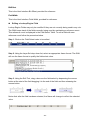
1
GEPON OLT
EPL-1000
User's Manual
-1-
Copyright
Copyright (C) 2009 PLANET Technology Corp. All rights reserved.
The products and programs described in this User’s Manual are licensed products of PLANET
Technology, This User’s Manual contains proprietary information protected by copyright, and this
User’s Manual and all accompanying hardware, software, and documentation are copyrighted.
No part of this User’s Manual may be copied, photocopied, reproduced, translated, or reduced to
any electronic medium or machine-readable form by any means by electronic or mechanical.
Including photocopying, recording, or information storage and retrieval systems, for any purpose
other than the purchaser's personal use, and without the prior express written permission of
PLANET Technology.
Disclaimer
PLANET Technology does not warrant that the hardware will work properly in all environments
and applications, and makes no warranty and representation, either implied or expressed, with
respect to the quality, performance, merchantability, or fitness for a particular purpose.
PLANET has made every effort to ensure that this User’s Manual is accurate; PLANET disclaims
liability for any inaccuracies or omissions that may have occurred.
Information in this User’s Manual is subject to change without notice and does not represent a
commitment on the part of PLANET. PLANET assumes no responsibility for any inaccuracies that
may be contained in this User’s Manual. PLANET makes no commitment to update or keep
current the information in this User’s Manual, and reserves the right to make improvements to this
User’s Manual and/or to the products described in this User’s Manual, at any time without notice.
If you find information in this manual that is incorrect, misleading, or incomplete, we would
appreciate your comments and suggestions.
FCC Warning
This equipment has been tested and found to comply with the limits for a Class B digital device,
pursuant to Part 15 of the FCC Rules. These limits are designed to provide reasonable protection
against harmful interference when the equipment is operated in a commercial environment. This
equipment generates, uses, and can radiate radio frequency energy and, if not installed and used
in accordance with the Instruction manual, may cause harmful interference to radio
communications. Operation of this equipment in a residential area is likely to cause harmful
interference in which case the user will be required to correct the interference at his own
expense.
FCC Caution
To assure continued compliance (example-use only shielded interface cables when connecting to
computer or peripheral devices). Any changes or modifications not expressly approved by the
party responsible for compliance could void the user’s authority to operate the equipment.
This device complies with Part 15 of the FCC Rules. Operation is subject to the Following two
conditions: (1) This device may not cause harmful interference, and (2) this Device must accept
any interference received, including interference that may cause undesired operation.
CE mark Warning
The is a class B device, In a domestic environment, this product may cause radio interference, in
which case the user may be required to take adequate measures.
-2-
Trademarks
The PLANET logo is a trademark of PLANET Technology. This documentation may refer to
numerous hardware and software products by their trade names. In most, if not all cases, these
designations are claimed as trademarks or registered trademarks by their respective companies.
WEEE Warning
To avoid the potential effects on the environment and human health as a result of
the presence of hazardous substances in electrical and electronic equipment,
end users of electrical and electronic equipment should understand the meaning
of the crossed-out wheeled bin symbol. Do not dispose of WEEE as unsorted
municipal waste and have to collect such WEEE separately.
Safety
This equipment is designed with the utmost care for the safety of those who install and use it.
However, special attention must be paid to the dangers of electric shock and static electricity
when working with electrical equipment. All guidelines of this and of the computer manufacture
must therefore be allowed at all times to ensure the safe use of the equipment.
Revision
User’s Manual for PLANET GEPON OLT
Model: EPL-1000
Rev: 1.0 (Aug. 2009)
Part No.: EM-EPL1000_v1
-3-
Table of Contents
1. Introduction ............................................................................................................... 6
1.1 Product Features ............................................................................................... 7
1.2 Package Contents.............................................................................................. 7
1.3 Application ......................................................................................................... 8
1.4 Outlook ..............................................................................................................11
1.5 Technical Specifications ................................................................................. 13
2. Installation ............................................................................................................... 15
2.1 Pre-Installation ................................................................................................. 15
2.2 Hardware Installation....................................................................................... 16
Step 1. Mounting the EPL-1000.................................................................... 17
Step 2. Power Connections.......................................................................... 18
Step 3. Connecting the Uplink Interface ..................................................... 19
Step 4. Connecting the PON Interface ........................................................ 20
Step 5. Connecting the Console and MGMT Port....................................... 21
2.3 Software Installation ........................................................................................ 22
2.3.1 Console Port Command Line Interface.............................................. 22
2.3.2 GUI Utility Installation.......................................................................... 24
3. System Configuration Introduction ....................................................................... 26
3.1 System Introduction ........................................................................................ 26
3.2 Software Introduction...................................................................................... 28
3.2.1 Basic Structure of GUI Software......................................................... 29
3.2.2 GUI Start Up Sequence........................................................................ 29
3.2.3 Note on the GUI data Path................................................................... 30
3.3 Basic Operation of the GUI ............................................................................. 31
3.3.1 Apply Button ........................................................................................ 31
3.3.2 Refresh Button ..................................................................................... 31
3.3.3 Revert Button ....................................................................................... 32
3.3.4 Defaults Button .................................................................................... 32
4. OLT System Configuration ..................................................................................... 33
4.1 OLT Network Parameters ................................................................................ 34
4.2 DBA ................................................................................................................... 35
4.2.1 Broadcast SLA ..................................................................................... 35
4.2.2 Aggregate Shaper ................................................................................ 36
4.2.3 Priority Range ...................................................................................... 36
4.2.5 DBA Drop Down Weights .................................................................... 37
4.2.6 Polling Rates ........................................................................................ 38
4.2.7 Service Level Agreement .................................................................... 39
4.3 OLT Port Management..................................................................................... 41
4.3.1 Configuring Port in Loop .................................................................... 41
4.3.2 Manage Flow Ctrl Parameters............................................................. 41
4.4 OLT Traffic Management ................................................................................. 42
4.4.1 Bridging Configuration Bridging ........................................................ 42
4.4.2 Provisioning Filtering Rules ............................................................... 47
4.4.3 L3 Switching......................................................................................... 50
4.5 Alarm................................................................................................................. 52
4.5.1 Viewing Alarms .................................................................................... 52
4.5.2 Enabling alarm auditing ...................................................................... 54
-4-
4.5.3 Setting Alarm Thresholds ................................................................... 55
4.5.4 Enabling Alarm Soaking...................................................................... 56
4.6 ONU Data Path Configuration ......................................................................... 57
4.6.1 Queue Configuration ........................................................................... 57
4.6.2 Selecting Lookup Fields...................................................................... 62
4.6.3 Designing the ONU Classification Scheme ....................................... 66
4.6.4 Provisioning Filtering Rules ............................................................... 71
4.7 IGMP.................................................................................................................. 75
4.7.1 Brief Overview of Proxy Concepts ..................................................... 75
4.7.2 GUI Authentication Function .............................................................. 78
4.8 Software Upgrade ............................................................................................ 79
4.8.1 OLT software upgrade......................................................................... 79
4.8.2 ONU Upgrade ....................................................................................... 81
-5-
1. Introduction
EPON is a point to multipoint communications protocol based on Gigabit Ethernet. It
allows a Gigabit Ethernet communications fiber to be shared by multiple end users using
a passive optical splitter. EPON communication takes place between an Optical Line
Terminal (OLT) and multiple Optical Network Units (ONUs). Using standard terminology,
downstream traffic flows from OLT to ONU, and upstream traffic flows from ONU to OLT.
A protocol called Multi Point Control Protocol (MPCP) is used to arbitrate the channel
between the ONU’s so that no collisions will occur on the common fiber.
With growing network services such as HDTV, IPTV, voice-over-IP (VoIP) and Multimedia
broadband applications, and the demand of broadband rises quickly. The present
Broadband environment has not already accorded with needing; however, Passive
Optical Network (PON) would be the most promising NGN (Next Generation Networking)
technology to fulfill the demand.
PLANET EPL-1000 is a GEPON Optical Line Terminal (OLT) which designed with one
GEPON port, one Gigabit TP / SFP Combo Interface and one management port. It is
easy installation and maintenance for GEPON deployment. Applications with PLANET
GEPON Optical Network Units (ONU) EPN series, PLANET EPL-1000 can provide highly
effective GEPON solutions and convenient management for Broadband network.
PLANET GEPON technology provides the high bandwidth up to 1.25Gbps for both
upstream and downstream, up to 20km Long-Distance Coverage between equipment
nodes, Scalability and Flexibility for network deployment. It is a cost-effective access
technology with reliable and scalable network for Triple-play service applications.
With high split ratio at 1:32 and support the usage of PLANET ONUs, EPL-1000 can
minimize the investment cost for carriers. By using the advanced technology in the
telecommunication industry, the EPL-1000 will provide strong functionalities for Ethernet
features such as QoS, VLAN, Multicast, DBA (Dynamic Bandwidth Allocation), and
Access Control List. The EPL-1000 is an ideal solution for FTTx applications.
-6-
1.1 Product Features
PON interface complies with IEEE 802.3ah
Supports 1 x PON Port and 1 x Gigabit TP / SFP Combo Interface
Up to 20Km Distance
Up to 1.25Gbps Upstream and Downstream
Dynamic bandwidth allocation (DBA) support
Supports IEEE 802.1q VLAN
Supports up to 4096 VLAN and 4K MAC Table
Supports IEEE 802.1p QoS
Point-to-multipoint network topology
LED indicators for link status
Enhanced IGMP features
User-Friendly GUI Management
One PON port supports maximum 32 ONUs
1.2 Package Contents
EPL-1000 Unit x 1
AC Power Cord x 1
Quick Installation Guide x 1
CD (Containing User’s Manual, QIG, Utility) x 1
Console Cable x 1
Rack-mounting x 2
Screw Package x 1
-7-
1.3 Application
High Bandwidth, Long Distance and Cost-Effective FTTx Applications
The PLANET EPL-1000 delivers high-speed voice, data and video services to residential
and business subscribers. Through the PON technology, the EPL-1000 offers competitive
advantages including a long-term life expectancy of the fiber infrastructure, lower operating
costs through the reduction of “active” components, supporting up to 20km distance
between equipment nodes, Easy Installation and Maintenance, and most importantly,
providing much greater bandwidth. The PLANET EPL-1000 is the perfect solution for FTTx
applications with cost-effective, scalability and flexibility for network deployment.
GEPON Applications
The OLT device is deployed in the central office room. The ONU devices are connected to
the OLT device through an optical splitter, which forms a P2MP (Point-to-Multipoint)
topology, connect to the switches or the devices as computers, IP Phone, IP Surveillance
and IPTV for Triple Play Service.
-8-
FTTx is the main trend and final target for the development of optical communication. It
can provide the high speed bandwidth to users without traffic jam.
GEPON technology is the most practical and feasible access solution for FTTx.
OLT is setup in the central equipment room of a community, to connect to the
backbone networks of data, video and voice applications.
ONU can be deployed at residential homes via passive optical distribute network that
spans up to 20km radius.
ONU can be put in a building or an end user’s room. A user can choose to use the
whole ONU alone or just one port of ONU, which is bandwidth configurable and
isolated from the rest ports of the ONU.
FTTH Application
-9-
FTTB Application
- 10 -
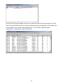
1.4 Outlook
Front Panel
The front panels of EPL-1000 are shown below.
EPL-1000
Front Panel LED Definition
LED
Status
Description
On
PWR
LNK/ACT
100M
MGMT
DUPLEX
COL
TX
RX
Uplink
1000
10/100
ALM1
ALM2
ALM3
Status
ALM4
OPT
SYS
RESET
The indicator will light when OLT is opened
Checking the power or power supply adaptor, make sure power supply has
Off
connected well
On
Light when equipment normally connect with 100Mbps ONU port
Glitter
Glitter when the port receive or transfer data
Corresponding indicator is on when 100Mbps equipment connect with
On
relevant port
Off
Be off when 100Mbps port does not joint equipment
On
Be on when port is working base on full duplex mode
Off
Be off when port is working base on half duplex mode
Glitter
Collision happens base on half duplex mode
Off
Normal work status
On
Be on when the 1000Mbps port is transferring data
Off
Be off when the 1000Mbps port has no data to transfer
On
Be on when the 1000Mbps port is receiving data
Off
Be off when the 1000Mbps port has no data to receive
On
Be on when 1000Mbps equipment connects with relevant port
Off
Be off when 1000Mbps port does not joint relevant equipment
On
Be on when 100Mbps equipment connects with relevant port
Off
Be off when the port does not joint 100Mbps equipment
Glitter
There will be one ONU or OLT alarm
Off
Normal work status
Glitter
There will be one ONU or OLT alarm
Off
Normal work status
Glitter
There will be one ONU or OLT alarm
Off
Normal work status
Glitter
There will be one ONU or OLT alarm
Off
Normal work status
Glitter
The link to the switch fiber port is failing
Off
The link to the switch fiber port is normal
Glitter
The link to the local 1000Mbps port is failing
Off
The link to the local 1000Mbps port is normal
ON when the system reset button is pushed
- 11 -
Front Panel Port Definition
Port
PON Port
Port Description
The PON connector allows data communication between the ONU and
the OLT through a single mode fiber.
Mini-GBIC Port
Gigabit Ethernet SFP trunk ports.
10/100/1000M Port
Gigabit Ethernet electrical trunk ports.
MGMT Port
RJ-45 (10/100Base-TX) Port for GUI Utility Management.
Console Port
RS-232 port for system configuration and maintenance. (9600, 8, N, 1)
RESET
Reboot EPL-1000
Rear Panel
Rear Panel Port Definition
Port
Port Description
AC PWR
AC Power cord plug-in, 100 - 240V AC is allowed.
Power Switch
Power On / Off switch
- 12 -
1.5 Technical Specifications
Product
GEPON OLT
Model
EPL-1000
Hardware
Transmission speed
Downstream: 1.25 Gbps
Upstream: 1.25 Gbps
Optical specification
Transmitter Power: >= 2 dBm
Receiver Sensitivity: >= -26 dBm
Optical split ratio
Up to 1:32
Ports Uplink Port
1 x Gigabit TP / SFP Combo Port ( SFP GbE + 10/100/1000Base-T )
PON Port
1 x PON Port
Console Port
RS-232 Serial Port (9600, 8, N, 1)
MGMT Port
1 x RJ-45 ( 10/100Base-TX)
LED Indicators
1 x Power LED
4 x MGMT LED
4 x Uplink Port LEDs
7 x Status LED
Software
EPON Features
−
Compliant with IEEE 802.3ah
−
802.3ah Forward Error Correction support
−
Operation Administration Management (OAM) protocol based on IEEE
802.3ah
−
Standard
Dynamic Bandwidth Allocation (DBA) Support
IEEE 802.3ah
IEEE 802.3
IEEE 802.3u
IEEE 802.3x
IEEE 802.3z
IEEE 802.1d
IEEE 802.1p
IEEE 802.1q
IEEE 802.1x
- 13 -
System Feature
−
MAC address learning and binding
−
Service Level Agreement (SLA) support
−
Unicast, broadcast and multicast traffic control
−
128-bit Advanced Encryption Standard (AES) encryption
−
MAC Filtering
−
Supports QoS based upon Port, IEEE802.1p, IPv4 Type of Service
(ToS) or Differentiated Services (Diff-Serv), IPv6 Traffic Class, 802.1Q
VLAN ID, Destination MAC address or Source MAC address
Management
−
Supports IGMP Proxy / Snooping
−
Remote loop-back test
−
Up to 256 Logical Link IDs (LLID)
−
IPv4 and IPv6 support
−
Up to 4096 VLAN support
−
4K MAC Addresses support
−
32 Queues (upstream / downstream)
−
User-Friendly GUI Utility
−
Local RS-232 CLI management
−
Firmware and Configuration upgradeable via Utility
−
Remote ONU Management
Environment Specification
Dimension (W x D x H) 432 x 207 x 43mm
Power
100 – 240V AC
Temperature
Operating temperature: 0 ~ 50 Degree C
Storage temperature: -30 ~ 60 Degree C
Humidity
Operating Humidity: 10 ~ 90% non-condensing
Storage Humidity: 5 ~ 95% non-condensing
Emission
FCC, CE
- 14 -
2. Installation
The followings are instructions for setting up PLANET EPL-1000. Refer to the illustration
and follow the simple steps below to quickly install your GEPON OLT.
2.1 Pre-Installation
This section provides the information users have to ware before installing the EPL-1000.
The information includes required installation tools, safety requirements, and electrostatic
discharge protection.
Tools and Test Equipment Requirements
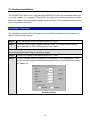
To install and maintain the EPL-1000, you should have the tools and test equipment listed
in the 錯誤! 找不到參照來源。.
Table 2-1
Required Installation Tools and Materials
Item Required
Purpose
Anti-static wrist strap
Protect the EPL-1000 system from electrostatic
discharge damage.
Hand tools
Screw drivers for equipment removal and
replacement.
Wire cutter/stripper
Prepare wires for electrical connections.
Safety Requirement
To prevent possible serious injury, do not apply power to the EPL-1000 system until you’ve
completed all of the installation procedures and connected it to the external facilities. Be
cautious, when turning on/off the EPL-1000 system power.
- 15 -
2.2 Hardware Installation
The PLANET EPL-1000 is a 1U high box-type GEPON OLT with rack-mountable enclosure.
It can be installed in a standard 19-inch rack by using the mounting brackets provided.
Mount the shelf on the rack using the large screws provided. The procedure to connect and
wire the system is as follows.
Installation Overview
The installation consists of the following procedures. Each procedure will be explained in
detail in the following sections:
Step 1: Mount the system into the desired location of a rack.
Step 2: Connect to the AC power supply, and then check the voltage. Make sure the
power is proper for EPL-1000 and plug in the Power.
After executing the previous procedures, please check the cable connection robustness
and correctness before turning on the power supply.
Step 3: Connect the network cable and optical to EPL-1000.
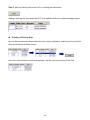
Step 4: Connect Console cable to COM port of a computer for CLI management. Then
run the terminal program with the setting shown below: Please see more details
on Chapter 4.2.
Console Setting
- 16 -
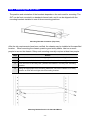
Step 1. Mounting the EPL-1000
The position and orientation of the brackets depends on the rack used for mounting. The
OLT can be front-mounted in a standard channel rack; and it can be shipped with the
mounting brackets installed in one of three mounting positions.
Mounting Bracket Orientation (Top View)
After the site requirements have been verified, the chassis may be installed at the specified
location. When mounting the chassis, practice good safety habits. Use two or more
people to secure the chassis. Relay rack mounting normally requires at least two people.
Step
Action
1
Locate the chassis and obtain the appropriate chassis mounting hardware.
2
Determine and obtain the tools required for the chassis mounting hardware.
3
From the front of the relay rack, position the chassis in its relay rack mounting
location.
4
Using the appropriate rack mounting hardware, secure the chassis in its relay
location on both left and right side of mounting bracket.
Mounting Bracket Position for Standard Mount
- 17 -
Note — The chassis should be empty during the chassis mounting procedures.
Remove any unit in the chassis, and store them according to
static-sensitive device storage procedures.
Warning — Hazardous voltages may exist on the chassis. Always practice good
safety habits when wiring a live circuit or performing maintenance.
Step 2. Power Connections
AC Power Connection
Connect the AC power cord to the AC supply socket on the rear panel of the OLT, and plug
the cord into the external power source. The voltage must be 100 to 240V AC (±10%
tolerance).
Warning — Ensure that all power sources to the chassis (power distribution
panel) are turned off during the connection.
- 18 -
Step 3. Connecting the Uplink Interface
Uplink Connection
The system supports one Gigabit TP / SFP Combo (SFP GbE and 10/100/1000Base-T)
Interface. You can select the proper media for your applications.
Mini-GBIC (SFP) Interface
Prepare a proper SFP module and install it into the optical trunk port. Then you can connect
fiber optics cabling that uses LC connectors or SC connectors (with the use of an optional
SC-to-LC adapter) to the fiber optics connector on the uplink port.
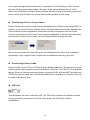
Fiber optics cable with LC duplex connector
Connecting optical fiber to the trunk port
Warning — Never look directly at the transmitting ports of optical
interface that might be emitting laser, in order to prevent damage to the
eye from the laser radiation.
- 19 -
RJ-45 Electrical Interface
The pin assignment of RJ-45 connector on the Uplink port is shown in the following figure
and table.
1,2
T/Rx+,T/Rx-
3,6
T/Rx+,T/Rx-
4,5
T/Rx+,T/Rx-
7,8
T/Rx+,T/Rx-
Step 4. Connecting the PON Interface
PON Connection
The system supports one fixed PON port, the max. Split ratio is up to 1:32 per PON port.
Connect the single mode fiber to the Splitter or ONUs. The PON port provides the high
bandwidth up to 1.25Gbps for both upstream and downstream, up to 20km Long-Distance
Coverage between equipment nodes.
- 20 -
Step 5. Connecting the Console and MGMT Port
You can use the Console Port and MGMT Port to manage the EPL-1000. The connection
figure is shown below; please follow next section to setup your system.
- 21 -
2.3 Software Installation
This section illustrates how to establish basic connectivity on the PON. After completing this
section the user will be able to transport packets across the system, and will be ready to
start advanced testing. The Software Setup consists of installing a Terminal utility to access
the Evaluation Kit CLIs and a sophisticated GUI to manage the system.
2.3.1 Console Port Command Line Interface
The EPL-1000 has a 10/100 Mb MGMT port in for the connection of a management GUI. It
also has Command Line Interface (CLI) access through a Console port on each board
(ONU and OLT). By connecting a straight-through serial cable to any board to a serial COM
port on a PC, the user can access each chip for low level diagnostics and debugging.
Although there are many commercial available Terminal Utilities such as MS Windows
HyperTerminal, Tera Term is used in this User’s manual as the Terminal Utility of choice.
Tera Term is recommended if you wish to perform firmware upgrades using the CLI. This
has been found to be the most reliable tool for downloading binary files to the ONU and OLT.
It can be downloaded for free from http://hp.vector.co.jp/authors/VA002416/teraterm.html.
Please download and install on each PC being used to connect to EPL-1000. Once
installed, configure the Transmit settings as follows.
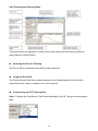
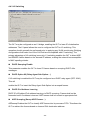
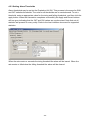
1) Setup the serial port by selecting “Serial Port” from the Tera Term “Setup” menu.
Tera Term Serial Port Settings
2) Set up the Serial port with the settings shown in 0 and click OK.
- 22 -
EPL-1000 GUI Personality Setup
The EPL-1000 supports a 10/100Mb Management interface for User-Friendly GUI
Management. Prior to installing the GUI, it may be necessary to modify the Host and
Management IP addresses configuration stored in the OLT personality flash. It can either be
left as the defaults or changed to suit your own network environment.
You can see what the current settings are by typing the following commands.
Commands shown below must be entered at the Tera Term command prompt for the
EPL-1000.
1) 3721/>pers [Enter]
2) 3721/pers/>show [Enter]
This will result in information about the state of the personality flash being displayed. The
items near the end of the prints are the current Management Interface Settings. Typically
the factory settings are:
Management interface settings:
Physical interface: ethernet
Management VLAN: 4095
Transport protocol: udp
Local IP config: static
Host IP config: static
Host IP: 192.168.1.100
Mgmt IP: 192.168.1.101
Netmask: 255.255.255.0
The Mgmt IP address refers to the IP address of the OLT 10/100Mb MGMT Port. The Host
IP address refers to the IP address of the PC which is running the GUI Utility. The default
settings are for both of these IP addresses to be statically assigned. The netmask should
be set to suit the class of the IP addresses. In addition to the 10/100Mb MGMT Port,
management can also be performed in-band. In this case the MGMT Port is not connected.
Instead the OLT is programmed for in-band management and the user sets the VID of the
VLAN used for management. The Transport protocol should always be set to UDP.
The following sections outline how to change the settings for each of the management
options.
MGMT Port – Static IP Addresses
If you are controlling the EPON system from a local PC connected directly to the
management port, these settings should suffice. Additionally if you have the OLT connected
to your network and you are using local addressing in the 192.168.1.x subnet, they will also
- 23 -
be appropriate. If on the other hand you wish to change them to match you local network,
you may do so as follows:
To change the IP Address assigned to the Host PC (this must match the Host PC IP
Address):
1) 3721/>pers [Enter]
2) 3721/pers/>hostip 192 168 1 100 [Enter]
To change the IP Address that is assigned to the OLT management port:
1) 3721/pers/>mgmtip 192 168 1 101 [Enter]
If you are not using Class C Addresses, you should also change the netmask to suit:
1) 3721/pers/>netmask 255 255 255 0 [Enter]
To make the new settings take effect you must reboot.
Prior to installing the GUI, you must set up your network adapter’s IP address to match the
setting found in the OLT’s personality flash (default = 192.168.1.100). Set the adapter’s IP
to match the value found in the personality flash for Host IP. Once the adaptor is set
appropriately, connect an Ethernet cable to the 10/100 Mb management port. In addition
you should also set the Management Port Parameters in the GUI’s Utilities -> Settings
dialog. These should match the settings found in the CLI.
2.3.2 GUI Utility Installation
The Utility comes with sophisticated software Graphical User Interface (GUI). It is highly
intuitive and allows the user to control the EPON and set such things as SLAs, bridging and
VLAN modes, static table entries, and to perform firmware upgrades etc. It is found in the
Utility folder on the CD provided. To install and use the GUI, do the following:
1) Copy the contents of your CD to the PC you will be using as your EPON management
PC.
2) Locate the Utility folder and create a shortcut to the GUI Utility.exe file and place on your
desktop or somewhere suitable.
3) Once you have connected all of the hardware, followed the instructions in the Initial
Power Up section, set the personality flash to suit your management interface method
you can start the GUI. The default MGMT IP is 192.168.1.101 and the Host IP is
192.168.1.100. Please make sure that the IP of your management PC is 192.168.1.100.
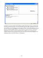
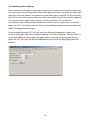
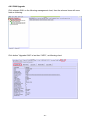
Double click on the GUI Utility Icon in the Utility folder or at the shortcut. The GUI should
start and you should see a window similar to the one shown as below figure.
- 24 -
If the OLT is running normally and the ONUs register each of their LLIDs, you should see
something similar to the figure. The left hand pane shows the MAC addresses of the OLT
and the ONU’s LLIDs. Depending on the number of ONUs, LLIDs, MAC addresses etc you
may see something slightly different. If the GUI fails to connect to the OLT, check the IP
addresses of the Host PC and the management port. Make sure you can ping the IP
address assigned to the management port. Also verify that the Host and management IP
addresses match in the GUI’s Utilities -> Settings tab.
- 25 -
3. System Configuration Introduction
3.1 System Introduction
PLANET EPL-1000 is a new generation of minitype GEPON OLT equipment, is a kind of
telecom FTTH bandwidth connecting equipment supplied for telecommunication dealer。
Perfect integration, applied flexibility, high reliability, managing, free expansibility, group
web and QoS guarantee are its features. EPL-1000 integrates EPON system based on the
IEEE802.3ah new standard,the fiber speed of upstream and downstream can be up to
1.25Gb/s。Each EPON system is available for max 1:32 WDM to transmit datas based on
forming fiber web by fiber and 32 EPONlong-distance ON equipments, with great capacity ,
excellent secrecy, web-grouping flexibility and saving the line resources and the quantity of
end equipments。
EPL-1000 , mainly used for FTTH project,make fiber to household come true, available for
VoIP、high-speed data, IPTV, etc;also manage the performance ,failure and deploy. It can
be put in CO side. Via the User-Friendy GUI Utility, administrator can manage and
configure the OLT and ONU equipment on central side.
Characteristics:
Compatibility
EPL-1000 is a mini-box-type equipment,only 1U size, easy installation and maintenance.
The EPL-1000 is fully compatible with PLANET ONU EPN-102 / 104, you can manage and
deploy the GEPON environment easily.
Long-distance
It is up to 20kms,and can save the cost of web-room construction and maintenance for
telecommunication dealer, as it is passive accessories。
High reliability
Recover after equipment regroups and the power interrupts unconventionally,the system
can come back to normal work quickly as the storage scheme.
- 26 -
Full QoS guarantee
Each PON supports up to 256 logic accesses,and single ONU can support many separate
logic accesses .For good Qos,it can adopt AES-128 encryption for each access, and
supports strong DBA,with powerful bandwidth sharing ability ,flexible bandwidth
management and increasing bandwidth using rate effectively; The double managing mode
based on SLA and PRI can ensure the users` mini bandwidth demand and low time-delay
requirement for the PRI operation。
Great OAM characteristic
EPL-1000 supports many operating and manageable telecom characteristics ,such as ONU
auto-detection, auto-registration,testing user connection, binding MAC address and
filtration, IP address binding and filtration、bandwidth control、VLAN(based on two divisiory
means of port and 802.1Q)、flow control、port aggregation, port mirror and broadcast
control.
- 27 -
3.2 Software Introduction
Preface
The Planet GEPON solution, including the OLT EPL-1000 and ONU EPN-102/104, all
designed by Teknovus GEPON technology. It is based on the TK37XX family. The
EPL-1000 is TK3721 OLT chipset and EPN-102/104 is TK-3715 ONU chipset. For
inconvenience, following information will use TK37XX to introduce the software
configuration.
This document is intended for engineers operating the TK37XX family of integrated EPON
solutions. The document explains how to use the TK37XX PC HOST GUI Utility, for the
purpose of evaluating the functionality and usability of TK37XX Host Interface Protocol.
This manual assumes that the reader has a technical background and a base level of
understanding regarding the basic operation of PON equipment, but does not assume any
prior experience using the TK37XX or any other product. The GUI Utility is a demonstration
package, intended for evaluation purposes only.
Organization of the GUI
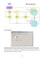
The screen real estate used by the GUI is divided — MDI style — into three sash windows.
The upper left panel displays the entities that may be managed by the TK37XX Host
Interface, including the OLT, ONUs and Logical Links. This sash window shall be referred to
as the Element Status Window. Left clicking on an entity with the mouse will open a tabbed
panel in the upper right sash window that may be used to manage the entity. This sash
window shall be referred to as the Entity Management Window. The bottommost sash
window is used for the purpose of logging the host interface message that are sent and
received by the GUI, and shall be referred to as the Message Log. The Message Log
displays the commands that are sent and received from the GUI as well as the raw bytes
sent and received by the physical layer interface.
- 28 -
3.2.1 Basic Structure of GUI Software
The GUI software breaks down into 4 logical layers the first layer is the physical interface.
The operating system, or driver resource, used to send and receive the raw Host Interface
messages. The next layer consists of the underlying messaging system used by the GUI.
This layer is responsible for parsing and queuing of Host Interface Messages as well as
providing reliability. The next layer is the application layer. This layers responsibility is to
display the GUI windows and provide services such as alarm auditing.
3.2.2 GUI Start Up Sequence
When the user invokes the GUI Utility.exe by double clicking on the T icon the GUI will
perform the following functions:
Step 0: Attempt to establish a UDP connection to the TK3721. This process will continue
indefinitely or until the connection is established.
Step 1: After the connection is established the GUI will test the interface by attempting to
send and receive a host interface message. The natural choice (and the choice that the
GUI will use) is the Get OLT Information. This message contains information about the
TK3721 that the host may use to identify product version information.
Step 2: Once the interface has been established the next step the GUI shall perform is to
obtain the list of discovered links. It should be noted that once the interface is detected the
GUI shall initiate a process to handle autonomous events. Receiving an autonomous event
will make the remaining sequence non-linear, as the autonomous events will be inserted
into the GUIs message queues with other response messages, refer to the note on the GUI
data path below.
Step 3: Once the GUI receives this list, it will query the links for the identity of their
associated ONUs by issuing a Get ONU Info Host Interface Message for each link found in
the list. Of course if an autonomous event (such as link discovery), occurs that event will
also be processed simultaneously with the querying process. If the GUI is configured to
authenticate its links, the link authentication will also take place. Again there is no set
- 29 -
sequence and multiple LLIDs may be authenticated simultaneously.
Step 4: Having discovered the known managed entities the GUI will next query the TK3721
for the list of blocked links. These links will be displayed in the list of unassociated links in
the managed entity status window. If the ONU is connected to the TK3721 and operating
properly, then unblocking a LLID will cause a new ONU to appear in the entity status
window. The LLID will be associated with this new ONU.
Step 5: After the GUI has finished querying the OLT, it will remain in the idle state until the
user performs some action. In the idle state the GUI will audit the OLT for alarm messages if
configured to do so, otherwise it will not send any Host Interface Messages until the GUI
operator directs it to do so, by initiating a query or provisioning action.
3.2.3 Note on the GUI data Path
The GUIs Data Path consists of simple non-blocking queuing mechanism that achieves
very good utilization of OLT recourses. However in such a system there is no set sequence
in which messages will be issued to the OLT. Thus that depending on very minor timing
differences between command response times, the GUI event log trace will be different. It is
important to note that all host interface messages are required to encapsulate a complete
set of provisioning operations and therefore do not require that provisioning actions be
performed in any set sequence.
- 30 -
3.3 Basic Operation of the GUI
As stated earlier, left-clicking the mouse on an entity in the Status Window shall cause an
associated tabbed dialog to appear in the Management Window. This dialog exposes
nearly the entire set of host interface commands associated with the managed entity. The
tabs are organized into roughly the same categories as the TK37XX Host Interface
document. And with few exceptions all of the panels function similarly.
GUI Controls
All controls in the GUI are derived from a common set of base classes and thus operate in
similar ways. Most panels include 1 or two buttons that invoke the GUI to perform various
transactions with the OLT. All such controls having the same basic function will also be
given the same label. For simplicity of understanding an explanation of each button type
appears bellow.
3.3.1 Apply Button
Most GUI panels manage only a single TK3721 Host Interface message. Every time the
panel is displayed the GUI will automatically query the OLT for the latest attributes by
issuing the appropriate Host Interface Message to the TK3721 firmware. If the query
operation is successful the panel will be updated with the latest values from the firmware.
As a general rule, when the panel is updated from a host interface message the associated
Apply button will be disabled to indicate that the values displayed are an accurate reflection
of the current state of the managed entity associated with the panel. If an error occurs the
Apply button will not be disabled indicating that the displayed values are not those of the
managed entity. Changing a GUI widgets value will cause the Apply button to be enabled
allowing the GUI operator to apply the new provisioning to the managed entity.
3.3.2 Refresh Button
Button’s labeled refresh are never disabled. The action associated with a Refresh button is
always to query the state of the associated attribute. The result of a successful Refresh
operation will be the same as if the panel is viewed for the first time. That is, the OLT will
query the managed entity associated with the panel, and if the operation completes the
Apply Button will be disabled.
- 31 -
3.3.3 Revert Button
The Revert Button had identical functionality to the Refresh button, but is semantically
different. The idea behind the Revert Button is that you can “revert” the panel’s state to the
initial state of the panel prior to changing a GUI widget. Semantically, once the apply button
has been pressed it is not possible to revert. The Revert Buttons are currently being phased
out in favor of the Refresh Button.
3.3.4 Defaults Button
The Defaults Button is used to restore the managed entity to the default settings found in
the Host Interface document. This mechanism employs a “canned” Host Interface Message
that will be issued to the OLT when the button action is invoked by left clicking on the
button.
For most commands a provisioning operation will also result in a subsequent query. In such
cases the Apply Button will not be disabled until the query operation completes. This audit
mechanism ensures that the values displayed by the panel are the same values stored in
the relevant managed entity. For a few Host Interface Messages the granularity of the data
is less than that of the provisioned value.
Some Apply actions result in multiple commands being issued to the OLT.
- 32 -
4. OLT System Configuration
This section describes the various panels found in the GUI, their function, and the method
by which they may be used to test the TK37XX Host Interface. The Panels are organized by
entity and generally follow the order in which they appear in the associated tabbed dialog
box. In the rare case that the GUI abstracts some detail of the host interface, a flow chart of
the message exchange sequence is presented. Where the message performs a complex
operation on the PON a related diagram may be present as a visual aid. Most panels are
subdivided into boxes with each box controlling exactly one host interface message. In
most cases the attributes are presented in the same order (as read from top to bottom) as
that in which they appear in the Host Interface Message. Thus for the most part the
remainder of this document is simply a rehashing of the descriptions already available in
the Host Interface Document.
Force link rediscovery de-registers a Logical Link, while allowing it to re-register, as if it had
been newly attached to the EPON network. This command is useful, for example, when the
Network operator wants to be able to force a re-arrival as part of their debugging process to
try to clear a problem, or to re-authenticate the user/ONU on that link.
The Block Link command prevents the given Logical Link (MAC address) from registering
on the EPON. The OLT will simply ignore registration requests from the blocked ONU. If the
given ONU is already registered, the Logical Link will be deregistered, causing the ONU to
depart from the network. All further requests to register from the ONU are ignored until the
Host issues an Unblock Link command.
Up to 256 ONU labels (MAC addresses) can be on the block list at one time.
Link blocking is intended to be a temporary measure used to suspend service for reasons
such as late payments or a troublesome customer. When the issue has been resolved, or
the ONU has been physically removed from the network and no longer requests service, it
can be removed from the blocked list with the Unblock Link command. If the ONU is still
connected to the network and attempting to register, the ONU will be once again allowed
onto the network.
Service provisioning such as SLAs or Bridging modes are not affected by the Block Link
command. Any ONU provisioning should be deleted with the appropriate other commands,
if desired. A blocked link will appear with a black status icon.
Please note the difference in the behavior with respect to the Block Link command where
an Unblock Link is required to undo its effect. Link Rediscovery invites the ONU to
re-register this link with the network, while Block Link prevents the ONU from returning on
that link after deregistration.
- 33 -
OLT Panel
The OLT panel is used to apply settings to OLT attributes. In some cases this may also
involve OAM transactions with ONUs. It should be noted that certain attributes of the OLT
such as SLAs are controlled via the Link Panel.
4.1 OLT Network Parameters
These commands allow the host to configure the way the PON will be managed.
OAM Rate
This command is used to view the default OAM rate
Loopback Timeout Value
This sets the loopback failsafe timer. If the operator sets a port in loopback mode the
loopback the OLT will initiate a count down timer for Loopback Timeout Value ms. When
the timer expires the loopback will automatically be canceled.
MPCP Parameters
Period
The interval at which the OLT will issue a discovery gate.
Window
The discovery window size in bytes.
VLAN Ethertype
This is the Ethertype value that the OLT will use to classify VLAN traffic (default = 0x8100)
- 34 -
4.2 DBA
The DBA tab allows the user to control virtually every parameter of the TK3721’s highly
flexible and efficient Hierarchal Weighted Round Robin DBA algorithm. The DBA algorithm
supplied with the OLT is similar to algorithms found in high performance ATM switches and
is capable of issuing 4 grants every 282 micro seconds, by far the fastest cycle time of any
EPON system deployed today. The TK3721’s DBA can meet 1 ms. Latency requirements
for high priority services in a 32 ONU deployment.
4.2.1 Broadcast SLA
This command is identical to the functionality of the Link SLA Panel except that it is used to
provision an SLA for the broadcast channel, as apposed to a unicast link. This unique
feature of the OLT allows the OLT To use its large 40Meg buffer ram to serve the
requirements of all ONUs, resulting in a 1:32 cost reduction (assuming 32 ONU
deployment).
- 35 -
4.2.2 Aggregate Shaper
This command lets the Host restrict the bandwidth available to the OLT for user data traffic
in each direction. This feature can be used to protect the core network from bursty
upstream flows and increase the accuracy of SLA enforcement. Aggregate bandwidth
control can be disabled by setting the parameters to zero; the feature is disabled by default.
For accurate Min SLA enforcement. recommends that the upstream aggregate shaper be
provisioned for 50-100Mbps less than the maximum bandwidth of the PON. Typical values
are 800-850Mbps.
4.2.3 Priority Range
The priority range determines how many links may be registered in each priority level. This
command should be applied immediately before registering any links, or after links are
deregistered using the Disable OLT command. It is a good idea to configure the OLT in
strict boot mode, allowing the host software time to apply this command and then explicitly
enable the OLT to register links.
The OLT must be disabled prior to applying this command; otherwise the OLT FIFOs will
become corrupt. It is recommend that this operation be performed once during the initial
bring up of the PON.
- 36 -
4.2.4 Shaper Drop Down Weights
This command is not available for the TK3721, and applies to future chipsets only. The
TK3721 has a strict priority FIFO scheduler.
4.2.5 DBA Drop Down Weights
DBA drop down weights are used by the DBA to reserve bandwidth for each priority level.
This allows the OLT to fix the latency and reserve a percentage of bandwidth for links in
each priority level.
The drop down weight for priority level n MUST be greater than or equal to the provisioned
DBA Weight for all links in priority level n + 1.
- 37 -
4.2.6 Polling Rates
The polling rates panel allows the operator to configure the rate at which each link will be
solicited to determine if it has any data to transmit. Smaller values result in lower latency
and increased overhead. For priority 0, the scheduling latency is approximately equal to the
larger of the polling rate and the cycle length.
- 38 -
4.2.7 Service Level Agreement
Every element scheduled by the OLT has an associated SLA record which can be
configured by the GUI or other host systems.
Every Logical Link registered by the TK3721 has an associated SLA maintained by the
TK3721, and stored internally in its NVS database (if enabled to do so). In the upstream
direction, the TK3721 uses a reporting mechanism specified by 802.3ah to monitor the
status of each registered link. When a particular Link’s FIFO(s) has data to send this
information will be conveyed to the OLT in the form of a report message. The OLT will use
this information and the SLA associated with the link to schedule a time slot in which the
link may transmit its data. Because the OLT schedules the links, rather than relying on
mechanisms in the ONU, service contracts are enforced in the central office, and excess
bandwidth may be allocated efficiently. SLA enforcement is accurate to within 2% of the
provisioned value.
Enable SLA
If checked, the OLT will allow the element to transmit user data.
Max Bw
Configures the maximum sustained rate at which a link may transmit data.
Min Bw
Configures the sustained rate at which the user may transmit without loss of data, this value
should always be less than or equal to Max Bw.
Mode
Determines the scheduler level
From the perspective of the GUI or other external devise managing the TK3721 “Delete”
semantically
- 39 -
equivalent to restore factory default and “Create” is equivalent to change the SLA from
default value.
It is important to note that though the logical link panel appears grouped under the ONU,
logical link attributes are NOT necessarily attributes of the ONU itself. Logical links
ALWAYS make two associations one with the ONU and one with the OLT. Unless explicitly
specified, logical link parameters may be parameters of the OLT, ONU or both. It is best to
assume that ALL operations performed on a logical link involve OAM transactions with the
ONU.
Though the TK3721 has a Min/Max FIFO scheduler in the upstream direction, the DBA is
not directly influenced by the Min scheduler. Instead it responds to signals generated by
queue depth. To ensure that the Min’s are scheduled accurately it is necessary to restrict
the total upstream bandwidth of the PON by 50 to 100Mbps. This can be accomplished by
provisioning an aggregate SLA.
As per IEEE 802.3ah, any ONU admitted to the network will be granted a small amount of
bandwidth sufficient for minimal OAM operation, even if the SLA is disabled. A disabled
SLA can use up to 256K. As per specification the ONU is not aware of SLA’s, and thus will
continue to transmit user data which will be dropped by the OLT. To prevent the ONU from
transmitting this unwanted data it is recommended that the ONU be configured in strict boot
mode. In this mode the ONU will ONLY transmit user data after the host software has
explicitly enabled it to do so.
In strict (or host driven) boot mode the SLA will be configured in the disabled state every
time the link is registered. In auto-boot mode the state of the SLA is enabled by default and
stored in the OLT NVS if NVS is enabled.
- 40 -
4.3 OLT Port Management
Allows the user a simple interface to control port parameters such as line speed and flow
control. If Auto Negotiation is enabled, the speed and duplex settings used will be based on
the result of negotiating with the link partner. Default values depend on the personality
settings. The table below describes the Set command. In the current firmware release, flow
control is not auto negotiated. If flow control is enabled the firmware will configure the Phy
to advertise flow control. Note however that pause frames will be transmitted regardless of
the capabilities reported by the link partner.
4.3.1 Configuring Port in Loop
Allows the user to set a loop back, currently the loop back position must be set to MAC.
4.3.2 Manage Flow Ctrl Parameters
Sets the flow control on/off threshold values.
For the Flow Ctrl thresholds: the precision of the values is less than the displayed
percentages. So small changes between the provisioned and actual value may exist
- 41 -
4.4 OLT Traffic Management
The traffic management panel allows the user to change bridging modes, apply complex
filters, and expose many of the OLTs advanced hardware and software features related to
traffic management.
4.4.1 Bridging Configuration Bridging
This panel facilitates provisioning of the bridging mode for each link, as well as the size of
the dynamic forwarding table on a per link basis. If the bridging mode supports VLAN, the
VLAN tag or tags may be specified using this panel. For certain VLAN modes such as
priority shared VLAN multiple links may be provisioned in the same VLAN. These modes
will make forwarding decisions based on multiple fields such as MAC address and VID.
A link may be provisioned in only one bridging mode. However, multiple links, each
provisioned in a different mode, may be associated with a given egress ONU port.
Changing the bridging mode for a particular logical link
Notice that after the bridging mode has been applied the Apply button will change to a grey
color.
- 42 -
Notice that after the VLAN has been provisioned the panel will change to a grey color. The
user must delete the VLAN provisioning before applying a new tag value.
Once a VLAN has been provisioned, the OLT will not permit the bridging mode to be
changed without first deleting the VLAN provisioning. If an attempt is made to change the
bridging mode, the GUI will display a dialog box allowing the user an opportunity to
automatically delete the VLAN provisioning.
Clicking “Yes” will delete the VLAN tag and change the bridging mode. Clicking “No” will
abort the operation. The exact panel used to apply VLAN provisioning will change based on
the provisioned VLAN mode.
Provisioning a link in a Dedicated VlAN
Dedicated VLAN modes associate a single VLAN tag with a particular Logical Link. The
provisioned priority field (CoS) will be added to upstream frames. However, only VID is
used to make a downstream bridging decision. VLANs are terminated by the TK3721.
Once a value has been entered for VLAN ID and Pri (CoS), the “Set” button may be used to
apply the provisioning. The “Clear” button is used to delete the provisioned tag.
- 43 -
Provisioning a link in a Shared
Shared VLAN modes associate multiple links with a single VLAN. The upstream CoS
inserted by the TK3721 is always 0.
Notice that the panel features a “Set” button similar to the panel used to provision the
dedicated VLAN. This button has identical functionality.
In addition to the VLAN provisioning box, a second box appears to the right that is used to
display a list of all logical links in the provisioned VLAN. No links will be displayed in this
box until the VLAN provisioning is applied. Clicking on a logical link in this list allows the
user to quickly change the context of the panel to the other logical link. This is useful when
changing links to a different VLAN.
Provisioning links in Transparent
Transparent VLAN uses the VLAN tag for downstream bridging decisions but does not
modify the tag. A single link may be provisioned with multiple VIDs. It should be noted that
the CoS field is not used for bridging decisions. Upstream frames shall be bridged
regardless of the Tag value.
The “Add” button is used to add a VID and the “Delete” button is used to remove a VID.
A box to the right of the provisioning window is used to display all of the VIDs associated
- 44 -
with a particular logical link provisioned in Transparent VLAN. Selecting a VID in the box
moves it into the provisioning window, allowing it to be quickly deleted. Once a VID is
deleted the VLAN field in the provisioning window will take on one of the other provisioned
values, allowing all VLANs to be quickly deleted with repetitive mouse clicks.
Provisioning links in a Cross Connect
Cross Connects are used to create a private link between two ONUs on the same PON. For
instance, a link Cross Connect might be used to facilitate data communication between two
offices within the same organization. Both links must be provisioned in the Link Cross
Connect mode before a Link Cross Connect can be established. Once both links have been
provisioned in Cross Connect mode, use the Connect button to bridge the links.
Once cross-connected the control will gray out indicating that the action was completed
successfully. Only a single Cross-Connect may be established with any given link.
Provisioning Priority VLANs
Priority VLANs use the ToS or CoS field to make bridging decisions. The decision of which
field should be used is based on a per link attribute, however, in the TK3721 this is a global
setting. Once one link has been provisioned in a priority VLAN, all links MUST provision the
ToS/CoS select the same way. It should be noted that if L3 switching is used only ToS may
be used for the priority field。
VID Field
This field allows the user to select the VID. The VID will be inserted into upstream frames
arriving on links provisioned in the VLAN. Downstream the VID will be used for
classification.
- 45 -
Upstream CoS
The upstream CoS is the CoS value that will be inserted into upstream frames, forwarded
on the VLAN. It is VERY important to notice that a unique upstream CoS and VID
combination defines a unique VLAN. For every link provisioned in a unique VLAN, EVERY
attribute in the VLAN record other than the link label, MUST be identical. Identical, means
that for link A and link B provisioned in VLAN C a bitwise comparison of the two records
used for provisioning would show equality. If this is not the case the TK3721 will not
function correctly, and NVS erase followed by system reset may be required to restore
proper functionality.
Max/Min Range
Allows the user to provision an INCLUSIVE range of priority values used for downstream
classification. Packets with matching VID and a CoS/ToS value in the range specified will
be classified onto the VLAN. It is VERY important that for every VID, there exists VLANs
{V0, V1, …,Vn} such that together they specify a complete range [0 7] with no holes. Also
note that for any two unique VLANs with VID=A, it is illegal that the two VLANs Max/Min
contain ANY overlapping regions (e.g. [0, 4] and [4, 7] would be illegal).
- 46 -
4.4.2 Provisioning Filtering Rules
This panel allows the operator to create rules to filter (drop received frames), based on
many different criteria (Rules).
Selecting the Port for Filtering
The Port to Filter is selected using the Port drop down box.
Using the Rule Grid
The Filtering Panel Rule Grid is almost identical to the Classification Panel Rule Grid,
except that the Q column is absent, as it is not required.
Constructing an OLT Filtering Rule
Step 1. Choose the Field Select. Field Selects defined by the OLT are given a descriptive
label.
- 47 -
Step 2. Choose an appropriate Operator. The operator tests the portion of the frame
specified by the field select.
Step 3. Choose an appropriate Lookup Value. This is the value that will be used by the
operator in the comparison. This step is only applicable to binary operators. If the operator
selected is unary (such as Field Exists) the Value field will be disabled.
Step 4. Add the clause to the Rule Editor using the left arrow button. Note that the right
arrow button can be used to remove a selected clause from the Rule Editor.
Step 5. Repeat steps 1-4 until the desired rule has been created.
Adding a Filtering Rule
Step 1. Select the Port to Filter.
Step 2. Set the rule precedence level. The Rule Level may be configured for 1 of 8 different
precedence levels, 0 being the highest priority and 7 being the lowest. Currently the
precedence level of user provisioned filtering rules is of little importance.
- 48 -
Step 3. Add the filtering rule to the OLT by clicking the Add button.
Adding a filtering rule will cause the OLT to be updated without an additional apply action.
Deleting a Filtering Rule
Once a filtering rules has been added the rule may be deleted by selecting it from the Rule
Grid and clicking the Delete button.
Once the rule has been successfully deleted it will be removed from the Rule Grid.
- 49 -
4.4.3 L3 Switching
The OLT may be configured as an L3 bridge, enabling the OLT to learn IPv4 destination
addresses. The L3 panel allows the user to configure the OLT for L3 switching. This
operation should generally be performed prior to applying any VLAN provisioning. Bridging
configurations that make use of the CoS field are incompatible with L3 switching. The
primary advantage of L3 switching is security. L3 switching enables the OLT to direct ARP
and RRARP frames based on the learned IP address, making the network less susceptible
to MAC spoofing attacks.
DHCP Snooping Enable
This parameter enables the OLT to learn IP frames based on snooping DHCP offer
messages.
DHCP Option 82 (Relay Agent Sub-Option…)
If L3 switching is enabled the OLT may be configured as a DHCP relay agent (RFC 3046.)
This will
enable the OLT to insert the Relay Agent Sub-Option into snooped frames.
DHCP IPv4 Address Learning
DHCP IPv4 Enables IPv4 address learning via DHCP snooping. Frames shall not be
forwarded until L3 address is learned. ARP frames shall be unicast to appropriate link.
ARP Snooping (Snoop ARP Frames…)
ARPsnoop Enables the OLT to classify ARP frames into its processor FIFO. This allows the
OLT to redirect the frames based on learned IPv4 destination address.
- 50 -
ARP Proxy
This is future functionality and will be described upon completion.
Dyn. IP Learn Table Size
Dyn. IP Learn Table Size Specifies the number of IP addresses that may be learned.
DHCP Relay Agent IP SA
Specifies the IP source address to be used for the relay agent. This is the address to be
used for grAddr ,inserted into DHCP frames modified by the OLT.
IPv4 Dynamic Filter Table
The learned IPv4 address table is exposed by the L3 Table tab on the GUI If any of the
checkboxes in the Mode box are checked the L3 switching shall be enabled. Otherwise L3
switching is disabled. If desired, Relay Agent IP SA may be provisioned with the same
value as the IGMP Proxy.
All L3 parameters must be selected in-order for the OLT to insert DHCP Option 82 into
upstream DHCP frames. Currently the OLT appends DHCP Option 82 to all L3 frames. The
Relay Agent IP must be an IP on the same subnet as the DHCP server. If the L3 switching
function is enable the Dyn. IP Learn. Table Size field should be provisioned with a non-zero
value.
- 51 -
4.5 Alarm
The OLT alarms manger works in concert with the ONUs to provide enhanced
management capabilities and complementary set of OLT specific alarms.
Features include:
A common management interface for ONU and OLT alarms
Soak of alarms on a per alarm ID basis
Auditing of all alarms known to the OLT
Setting of alarm thresholds for ONU and OLT alarms
Autonomous alarm reporting
Soak of alarms on a per alarm ID basis
4.5.1 Viewing Alarms
Unlike the ONU CLI the OLT CLI does not offer any ability to control the alarms manger.
Fortunately the Evaluation Kit GUI exposes all of the underlying functionality.
Observing Alarm Events
Alarm may be observed remotely via the Evaluation Kit GUI, in 4 ways:
The GUI Log Window will display all autonomous alarm messages received from the OLT’s
10/100 MGMT port. If alarm auditing is enabled the GUI may also be configured to display
messages received based on the audit.
The appropriate Status Icon will change to a yellow triangle indicating that an alarm is
raised.
The Active Alarms panel associated with the alarmed entity will indicate the exact alarm
that has been received from the host interface. This record will be maintained until an event
causes the alarm to clear. Alarms will be cleared when the GUI receives a clear alarm
message or another network event signifying that the alarm condition is no longer present.
- 52 -
The GUI Alarm Log will display a new entry, retained until the GUI is terminated. The GUI
Alarm Log will indicate the way in which a particular alarm was detected, or the reason why
it was cleared in the column labeled Disposition. The GUI has 3 different alarm
“dispositions”: autonomous, audit, and internal.
- 53 -
4.5.2 Enabling alarm auditing
The GUI can be configured to perform a periodic audit of the ONU and OLT alarms. By
default this feature is disabled. To enable Alarm auditing follow the steps below.
Step 1. Open the Settings dialog box as illustrated below:
Step 2. Click on the Audit alarms, check box. The Period field is used to determine the rate
at which a single ONU/OLT is audited. The GUI ensures that the time between audits
remain exactly the same for all entities.
Step 3. By default the GUI does not display the reports generated by alarm audits. To
enable the GUI to display alarm audits in the GUI Log Window, check the box labeled “Log
all alarm audits.”
Note that once changed, the GUI will write the new settings to a file named “default.conf”
that is located in the installation directory with the GUI. The next time the GUI is executed,
the new settings will be used by default. In some cases it is mandatory that the GUI be
reset in order for the new settings to take effect. Ifthe GUI is run from a read only volume
such as a CDROM, it will not be able to write the “default.conf” file and will fall back to
default settings. If the “default.conf” file becomes corrupt, or is deleted a new file will be
generated the next time the GUI is run.
- 54 -
4.5.3 Setting Alarm Thresholds
Alarm thresholds may be set via the Evaluation Kit GUI. This process is the same for ONU
and OLT statistics thresholds. The units for all thresholds are in events/second. To set a
threshold, enter an appropriate value for the rising and falling thresholds, and then click the
apply button. When the transaction completes successfully the Apply and Revert buttons
will turn grey indicating that the OLT and GUI values are synchronized. Note that not all
statistics are present for every entity. Refer to the host interface document for supported
statistics.
When the rate meets or exceeds the rising threshold the alarm will be issued. When the
rate meets or falls below the falling threshold the alarm will be cleared.
- 55 -
4.5.4 Enabling Alarm Soaking
Alarm soaking is controlled by selecting an alarm type to soak and entering the desired set
and clear times. Un-checking enable alarm will suppress all alarm events for the alarm type
specified. When the panel is first loaded or a new alarm type is selected, the GUI will query
the OLT for the current values. When the values have been retrieved they will be displayed
in the panel and the apply button will grey, indicating that the OLT and GUI are
synchronized. After the parameters have been entered, use the Apply button to transfer
them to the OLT. As before, once the GUI has successfully completed the transaction with
theOLT the apply button will grey.
In the example below the OLT will only notify the Element Management Layer of an
external dying gasp if the alarm condition persists for at least 5 seconds. After the alarm is
cleared an additional 10 seconds must pass (without receiving any dying gasp alarms)
before the OLT will notify the Element Management Layer that the dying gasp has been
cleared.
- 56 -
4.6 ONU Data Path Configuration
The GUI may be used to configure various aspects of the ONU data path. Such as the ONU
queue configuration, classification of user data traffic and filtering of user data traffic.
Because these operations are very complex the user interface is divided between several
panels.
4.6.1 Queue Configuration
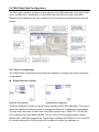
The ONU Queue configuration panel allows the operator to change queue sizes and save
configurations.
Entity Selection Control
Upstream Configuration
Downstream Configuration
The Entity Selection Control is a graphic representation of the ONU data path. This control
allows the operator to select an entity to manage by clicking on a graphical representation.
An entity many be either an ONU User Port ONU Logical Link, or ONU FIFO. The EPON
port is depicted as a box labeled EPON. The two User Ports are represented by boxes
labeled UNI-1 and UNI-2 respectively. Depending on whether the EPON Port or a User Port
is currently selected the FIFOs shown will correspond to either the upstream or
- 57 -
downstream data path. The convention is “from port to FIFO.” Thus selecting a port “from”
which a frame is received displays the FIFOs to which the frame may be classified.
Classification will be discussed in the next section. Selecting any FIFO terminating at a
particular port or logical link has the effect of also selecting the related entity. In the
example above link 1 has been selected.
Notice that downstream FIFOs are labeled relative to their associated link. For downstream
FIFOs the GUI uses the naming convention Link.FIFO. Therefore the “full name” of the
selected FIFO is 1.1.
Upstream the GUI will use the convention Port.FIFO. In the example above the full FIFO
name is 1.2, indicating that the FIFO is #2 of User Port 1.
Provisioning Number of Logical Links to Register
Up to 3 Links may be registered per ONU. The number of Logical Links is determined by
the Num LLID control. This control is only visible when one of the User Ports is selected.
- 58 -
Provisioning Number of User Ports
In practice either ONU user port may be used exclusively. However, for the purposes of the
GUI only User Port 1 may be used exclusively. To select whether both User Port 1 and 2
should be used, or only user port 1, set the number of ports to 2 (both ports) or 1 (only port
1). The number of ports will not be changed if all of the FIFOs have already been allocated
to user port 1, or there is insufficient FIFO space available. The Num Port field is only
visible if the EPON port is selected.
Provisioning Downstream FIFOs
Step 1. Downstream FIFOs are associated with ONU user ports. The Entity Selection
Control displays queues using a “From-To” convention. To add a queue to an ONU User
Port, first click on the ONU EPON port (“From”) and then select any one of the ONU User
Port’s FIFOs (“To”).
Step 2. Use the Num Qs control to add a second FIFO, by changing the value from 1 to 2.
Notice that a second FIFO will appear in the diagram as depicted in the figure above.
Step 3. Size the FIFOs using the Queue Size Control. Notice that as the size of a given
FIFO changes the picture will be updated to graphically illustrate the relative space
allocated to each FIFO. To calculate the FIFO size in KBytes, multiply the provisioned size
by the FIFO increment displayed on the panel. The remaining space is displayed on the
panel as the Flooding Q Size. This value is automatically updated when a change is made
to a User FIFO. Space that is left unallocated by the operator will automatically be assigned
to the Flooding FIFO by the GUI. It is important to note that not all configurations make use
of the Flooding FIFO, however all FIFOs including the Flooding FIFO must be allocated a
- 59 -
minimum queue space of 2KBytes, to ensure that there is enough free space to hold a 1536
byte packet. The exact purpose of the Flooding FIFO is beyond the scope of this document.
Provisioning Upstream FIFOs
Step 1. Adding a FIFO to an ONU Logical Link is a similar procedure. First click on either of
the ONU’s User Ports and then click on any of the existing FIFOs associated with the
logical link to which a new FIFO is to be added.
Step 2. Use the Num Qs control to add a second FIFO, by changing the value from 1 to 2.
Notice that a second FIFO will appear in the diagram as depicted in the figure above.
Step 3. Size the FIFOs using the Queue Size Control. Notice that as the size of a given
FIFO changes the picture will be updated to graphically illustrate the relative space
allocated to each FIFO. To calculate the FIFO size in KBytes, multiply the provisioned size
by the FIFO increment displayed on the panel. There is no upstream equivalent to the
Flooding FIFO, therefore all the queue space can be allocated to the User FIFOs.
- 60 -
Committing the Provision to ONU Firmware
Once a FIFO configuration has been created clicking the Apply button will commit the
changes to the ONU. The ONU MUST be reset to complete the configuration process (this
can be performed with the GUI). It should be noted that the GUI applies the new
Classification scheme with the FIFO configuration; this is INCORRECT behavior that will be
fixed in a future version of the GUI. Well behaved host software should apply the
classification rules only after the ONU has been reset. The refresh button performs the
converse function of Apply, causing the GUI state to be updated to reflect the state of the
ONU.
Saving the Configuration to the Hard Disk
Once a queue configuration has been created, it can be saved to the hard disk by entering
a descriptive name for the configuration into the Quck Cfg drop down box and clicking the
Save button. The GUI will save both the Queue Configuration and the Classification
Scheme (Filtering Rules will not be saved). These attributes are stored in a binary file
located in the distribution directory. This file is called “OnuQueueCfgRepository.dat”. If
desired the file may moved to a newer distribution to recover the saved configurations.
Restoring the ONU to a Previous Configuration
To restore an ONU to a previous configuration, select the configuration from the Quick Cfg
drop down box and press the Apply button to transfer the stored configuration to the ONU.
Deleting a Saved Configuration
Once a configuration has been saved, it can be deleted by selecting it from the Quick Cfg
drop down box or typing its name and clicking the Delete button.
Notice that the GUI prevents the user from adding more FIFOs than the ONU supports. It
will also prevent the user from adding a second FIFO if there is no free space available. The
free space available is clearly displayed so that it is easy to determine when there is no
longer sufficient resources.
- 61 -
It is important to note that not all configurations make use of the Flooding FIFO, however all
FIFOs including the Flooding FIFO must be allocated a minimum queue space of 2KBytes,
to ensure that there is enough free space to hold a 1536 byte packet. The GUI enforces this
restriction.
Picking the right FIFO size is easy. In a typical configuration the ONU is Burst Tolerant to
the provisioned FIFO Size. A typical PC running Windows XP has a default TCP Window
size of 17K. Therefore the FIFO should be at least 17K if it is to carry PC data. Typically
4-10K is enough for voice traffic depending on the type of service. Generally speaking 32K
of Burst Tolerance is more than adequate for high throughput applications such as FTP.
The ONU MUST be reset to complete the configuration process (this can be performed with
the GUI). It should be noted that the GUI applies the new Classification scheme with the
FIFO configuration; this is INCORRECT behavior that will be fixed in a future version of the
GUI. Well behaved host software should apply the classification rules only after the ONU
has been reset.
4.6.2 Selecting Lookup Fields
The TK37XX and future ONUs support highly configurable line rate classification engines.
Depending on the model, the ONU lookup engine is capable of simultaneously examining
anywhere from 8-12 fields in the frame! The position and size of each field is programmed
into the lookup engine prior to use in filtering and classification rules.
Depending on the device the ONU reserves a certain number of fields that cannot be
changed by the user. These fields may be used to construct user provisioned classification
and filtering rules, however their definitions may not be changed. All of the currently
provisioned fields including those reserved by the ONU may be viewed by clicking on the
Edit Fields tab.
- 62 -
Selecting a Classification Engine
Most ONU classification engines are configured on a per port basis. However, the TK37XX
supports only upstream and downstream classification. The Port field allows the operator to
choose the set of field selects to modify. Depending on the port that is chosen the
provisioning may be different. For ONUs supporting only upstream and downstream
classification, the EPON port designates downstream, and selecting either User Port
selects upstream.
Field Select Table
The Field Select Table displays the Field Selects associated with the currently selected port,
and allows field selects to be selected for modification.
Index
A number used to identify the field select.
Name
An ASCII description of the field select.
RefCount
The number of rules currently using the filed select. A non-zero value means that the field
select may not
be modified.
LayerSel
This is the Host Interface layer select value provided for reference.
Dword
This is the Host Interface Dword value, provided for reference.
- 63 -
BitOffset
This is the Host Interface Bit Offset, provided for reference.
FieldWidth
This is the Host Interface Field Width, provided for reference.
Editing a Lookup Engine Field
Lookup Engine Fields may only be modified if they are not currently being used in any rule.
The ONU keeps track of the fields currently being used by maintaining a reference count.
This reference count is displayed in the Field Select Table. To edit a field with zero
reference count follow the procedure below.
Step 1. Click on the Field Select index to be edited.
Step 2. Using the Layer Sel drop down list, select an appropriate frame format. The ONU
will use the frame format to qualify the field select value.
Step 3. Using the Edit Tool, drag a box over the field select by depressing the mouse
button at the start of the field dragging it to the end of the field and then releasing the
mouse button.
Notice that after the field has been selected, the Name will change to reflect the selected
value.
- 64 -
Applying the Configuration
The field select values may be applied to the ONU by clicking on the Apply button.
Refreshing the View
To refresh the currently displayed field select values to match the ONU click the apply
button.
Lookup Engine Fields may NOT be modified if they are in use. The ONU keeps track of the
fields currently being used by maintaining a reference count. Most ONU classification
engines are configured on a per port basis. However, the TK37XX supports only upstream
and downstream classification. The Port field allows the operator to choose the set of field
selects to modify. Depending on the port that is chosen the provisioning may be different.
For ONUs supporting only upstream and downstream classification, the EPON port
designates downstream, and selecting either User Port selects upstream.
- 65 -
4.6.3 Designing the ONU Classification Scheme
An ONU classification scheme allows the operator to define a custom function to determine
which packets will be forwarded to each of the ONUs configured priority FIFOs. The
classification function for a given FIFO is composed of multiple independent rules. A rule
consists of multiple ANDed expressions known as clauses. Each rule is used to classify
traffic into a single FIFO, 1 or more rules may be used to classify traffic into the same FIFO.
Constructing an ONU Classification Rule
Step 1. Choose the Field Select. Field Selects defined by the ONU are given a descriptive
label. User Defined field selects are labeled User 1, User 2.., User N. All field select labels
begin with an index value. The index value correlates with the index value on the Edit Field
panel.
Step 2. Choose an appropriate Operator. The operator tests the portion of the frame
specified by the field select.
- 66 -
Step 3. Choose an appropriate Lookup Value. This is the value that will be used by the
operator in the comparison. This step is only applicable to binary operators. If the operator
selected is unary (such as Field Exists) the Value field will be disabled.
Step 4. Add the clause to the Rule Editor using the left arrow button. Note that the right
arrow button can be used to remove a selected clause from the Rule Editor.
Step 5. Repeat steps 1-4 until the desired rule has been created.
The right arrow button is useful for correcting mistakes. Using this button we can remove a
selected clause that is incorrect.
Using the Rule Gri
The Rule Grid is used to view the classification scheme and delete unwanted Classification
Rules. The Rule Grid displays the rules for the port that is currently selected. Selecting a
different port will reveal the rules associated with that port.
Adding a Rule to the Classification Scheme
Step 1. Set the rule precedence level. The Rule Level may be configured for 1 of 8 different
precedence levels, 0 being the highest priority and 7 being the lowest. The ONU firmware
installs system rules at precedence levels 0..3 and 7. It is recommended that user
provisioned classification rules be provisioned in the range that the ONU does not use. If
two rules (classifying traffic into different FIFOs) match the same frame, the provisioned
- 67 -
Rule Level will determine where the frame is classified. A classification rule with higher
precedence than a filtering rule can be used to override a filtering function.
Step 2. Select the FIFO for classification. First select the ingress port (the port the classified
frame arrives at), next select the egress FIFO (the FIFO that the frame will be classified
into). Notice that selecting an ingress port automatically selects the set of available egress
FIFOs. Black lines drawn from the FIFO to the ONU port indicate which port the forwarded
frames will be sent to. Arrowhead serve to indicate the direction the data will be transported
(in the figure below the direction is upstream).
ALL downstream classification rules MUST include a clause to indicate the link on which
the forwarded frames arrive. The consequences of not inserting this clause are unknown,
but random device failure is a possibility! The ONLY supported operator for this rule is: “==.”
The Link Index is the same as N, where Base MAC + N = Link MAC.
Selecting an ingress port automatically selects the set of available egress FIFOs. Black
lines drawn from the FIFO to the ONU port indicate which port the forwarded frames will be
sent to. Arrowhead serve to indicate the direction the data will be transported.
If two Classification Rules or a Classification Rule and a Filtering Rule (next section) match
the same frame, the action associated with the HIGHEST priority rule will be carried out (0
is highest priority). If the precedence levels MATCH the action is UNDEFINED!
Step 3. Adding the classification rule to the ONU. Once we have selected the FIFO for
classification adding the rule is as simple as clicking the Add button. The GUI software will
not allow the addition of identical rules.
Adding the rule will cause the Entity Selection Control to draw a connection from the
- 68 -
selected port to the selected FIFO for classification. The Rule Grid will also be updated to
display the new rule.
Deleting a Rule
To delete a rule from the Classification Scheme, simply click any where in the rule to select
it, and then click the delete button.
Understanding FIFO Labeling (Q)
The GUI Uses the convention <Entity ID>.<FIFO Number> to denote a particular FIFO. The
Entity ID corresponds to link index upstream, and the ONU User Port upstream. If you
forgot to add the Link Index clause to your downstream classification rules your ONU might
disappear into an alternate universe (you have been warned). For instance the label 2.0
indicates the 0th FIFO associated with link 2.
- 69 -
Applying the Configuration
Once the configuration has been completed it may be easily applied to the ONU by clicking
the Apply button.
The Apply All button is used to apply the configuration to all ONUs on the PON.
Once the configuration has been applied the ONU MUST be reset. This is because the GUI
also applies both the Classification Scheme and the FIFO Configuration together. This is an
issue in the GUI that will be fixed in a future software release. Properly designed hosts
MUST NEVER apply a new Classification Scheme after changing the FIFO Configuration
until after the ONU has been reset. The Reset ALL ONUs is convenient when multiple
ONUs must be reset.
Refreshing the View
The Refresh button is used to refresh the Classification Scheme with the values currently
stored in the ONU.
Once the configuration has been applied the ONU MUST be reset. This is because the GUI
also applies both the Classification Scheme and the FIFO Configuration together. This is an
issue in the GUI that will be fixed in a future software release. Properly designed hosts
MUST NEVER apply a new Classification Scheme after changing the FIFO Configuration
until AFTER the ONU has been reset. The Reset ALL ONUs is convenient when multiple
ONUs must be reset.
- 70 -
4.6.4 Provisioning Filtering Rules
Filtering Rules and Classification Rules work in apposing directions to achieve the same
ultimate goal: control the user’s access to the PON. In the previous section we learned that
Classification Rules are used to allow certain classes of traffic into the ONU data path. As
you might imagine, Filtering Rules serve the opposite purpose, blocking certain classes of
traffic from entering an ONU Port. Filtering rules use the same hardware resources, Field
Selects, Operators, and Precedence values as Classification Rules and are constructed in
a similar fashion. A Classification Rule can override a Filtering Rule by setting its
precedence higher.
Selecting the Port for Filtering
The Port to Filter is selected using the Port drop down box.
Using the Rule Grid
The Filtering Panel Rule Grid is almost identical to the Classification Panel Rule Grid,
except that the Q column is absent, as it is not required.
- 71 -
Constructing an ONU Filtering Rule
Step 1. Choose the Field Select. Field Selects defined by the ONU are given a descriptive
label. User Defined field selects are labeled User 1, User 2.., User N. All field select labels
begin with an index value. The index value correlates with the index value on the Edit Field
panel.
Step 2. Choose an appropriate Operator. The operator tests the portion of the frame
specified by the field select.
Step 3. Choose an appropriate Lookup Value. This is the value that will be used by the
operator in the comparison. This step is only applicable to binary operators. If the operator
selected is unary (such as Field Exists) the Value field will be disabled.
Step 4. Add the clause to the Rule Editor using the left arrow button. Note that the right
arrow button can be used to remove a selected clause from the Rule Editor.
Step 5. Repeat steps 1-4 until the desired rule has been created.
- 72 -
Adding a Filtering Rule
Step 1. Select the Port to Filter.
Step 2. Set the rule precedence level. The Rule Level may be configured for 1 of 8 different
precedence levels, 0 being the highest priority and 7 being the lowest. The ONU firmware
installs system rules at precedence levels 0..3 and 7. It is recommended that user
provisioned classification rules be provisioned in the range that the ONU does not use. If
two rules (classifying traffic into different FIFOs) match the same frame, the provisioned
Rule Level will determine where the frame is classified. A classification rule with higher
precedence than a filtering rule can be used to override a filtering function.
Step 3. Add the filtering rule to the ONU by clicking the Add button.
Unlike the Classification panel, adding a filtering rule will cause the ONU to be updated
without an additional apply action.
The TK37XX ONU support 8 clauses per rule. It is important to consider the capabilities and
limitations of each chipset when designing filtering schemes.
- 73 -
Deleting a Filtering Rule
Once a filtering rules has been added the rule may be deleted by selecting it from the Rule
Grid and clicking the Delete button.
Once the rule has been successfully deleted it will be removed from the Rule Grid.
- 74 -
4.7 IGMP
EPON chipsets include an RFC 2236 compliant IGMP solution that leverages the power of
the underlying hardware classifiers, shapers and priority FIFOs to deliver high quality IP
multicast content over EPON. From a functional perspective the feature set may be roughly
divided into 4 broad classes of functionality:
1. Control over IP multicast data traffic at the network and customer edge.
2. Burst protection for customer premise equipment (CPE.)
3. Scheduling of IP multicast data traffic.
4. Aggregation of reports sent by CPE, greatly limit the burdon placed on RFC 2236
queriers such as a video server residing in the CO.
These 4 primary functions are distributed between the OLT and the several ONUs, based
on the design principle that functionality should be implemented, as much as possible, at
the network’s edges. Thus preserving the bandwidth of the PON and taking maximum
advantage of the combined resources of the several ONUs.
4.7.1 Brief Overview of Proxy Concepts
On the customer edge the OLT acts as an RFC 2236 querier. Hosts connected to one of the
ONUs UNI ports perceive the queries sent by the OLT as originating from a media server
behind the OLT. On the network edge the OLT behaves as an RFC 2236 “non-querier,”
aggregating the reports sent by the several connected hosts, and making the system
appear to an attached video server or other device connected to the OLT’s NNI as if there
existed only a single STB behind the OLT.
Behavior of ONU
By default the ONU shall block all IGMP multicast data traffic preserving the bandwidth of
the user network. When an STB or other host attached to one of the ONU’s UNI ports
requests to join a multicast group, the query is snooped by the ONU’s CPU before being
forwarded to the EPON port without modification.
Report Received from UNI
If no host is joined to the group on the attached interface, the ONU will install a new rule to
forward the group to the provisioned IGMP multicast data FIFO.
Leave Received from UNI
If the LMQC variable is set to 0 (“fast leave”) and at least one host is joined to the group on
the attached interface, the ONU will remove the forwarding rule for the associated group.
- 75 -
General Query Received from EPON
If any groups are present on either of the ONUs UNI ports, the ONU will start a count down
timer that is equal to: [provisioned robustness count] * [Max Response Time specified in
query]. If a report is not received within this interval, for any group joined on either of the
ONU’s UNI ports, the group will be removed from the ONU’s multicast forwarding table.
Group Specific Query Received from EPON
If any groups are present on either of the ONUs UNI ports, the ONU will start a count down
timer that is equal to: [provisioned GSQC] * [Max Response Time specified in query]. If a
report is not received within this interval, for the specified group joined on either of the
ONU’s UNI ports, the group will be removed from the ONU’s multicast forwarding table.
Behavior of OLT
By default the OLT shall block all IGMP multicast data traffic preserving the bandwidth of
the PON and user network. When an STB or other host attached to one of the several
ONU’s UNI ports requests to join a multicast group, the query is snooped by the OLT’s CPU,
and conditionally forwarded upstream.
Report Received from Logical Link
If no host is joined to the group on the attached interface, the OLT will install a new rule to
forward the group to one of the several IGMP multicast data FIFOs. The OLT will pick the
FIFO with least groups joined.
Group Insertion Process:
Leave Received from Logical Link
The OLT will issue LMQC GSQs, spaced by LMQI until one of the following two events
occurs (whichever occurs first).
1. 1 or more reports are received upstream for the group specified in the leave message.
2. No report is received after LMQI units from the time that the final LMQ was issued.
In case (1), the load balancing algorithm will be applied as described above. In case (2) the
group will be removed from the forwarding table, and the OLT will transmit a leave message,
with the provisioned source IPv4 Address, from the OLT’s NNI.
- 76 -
Group Removal Process:
General Query Issued
The OLT will periodically issue General Queries every Query Interval units. The use of the
General Query in IGMPv2 is very different from the way it was used in IGMPv1. In IGMPv2
the General Query is used for failure detection only. In IGMPv1 the General Query was the
only mechanism used to detect a leave. Because failures are extremely rare in modern
networks the Query Interval may be provisioned to a very large value. Query Response
Timeout units after the OLT issues the General Query the OLT will decrement the
robustness variable for each group joined for which the OLT has not received a report.
When the robustness for a particular group is 0, the OLT will assume that an implicit leave
has occurred and start the same process as described above. Since IGMPv2 has a
different mechanism than IGMPv1 to guarantee robustness - the Group Specific Query
Count - it is probably not necessary to provision the Robustness Count to a large value.
The value recommend by the standard for backwards compatibility with IGMPv1 is 2,
however, if the target system will only have IGMPv2 capable clients, a robustness count of
1, is probably a better choice.
The protocol description assumes that IGMP snooping and proxy are enabled. If these
functions are disabled, IGMP multicast data packets will be forwarded based on the Host
provisioned classification scheme and bridging mode(s).
If faster leave operation is desired, the GSQC may be set to 1, and the Last Member Query
Max Response Time provisioned to a smaller value than the default.
The ONU Snooping and OLT Proxy functions MUST be configured identically. Otherwise
multicast traffic will NOT be forwarded as expected.
The number of IGMP multicast data FIFOs used MUST NOT be changed when the OLT
PON Plant is enabled.
- 77 -
4.7.2 GUI Authentication Function
The authentication function in the GUI requires the creation of an external database of
authentication secrets. The external database is to be a plain ASCII text file named
“Prov.db”. The first line in the database contains the number of authentication records.
Each record consists of an LLID MAC Address, end-line, authentication secret, and
end-line.
Example File:
Three Boolean attributes found in the Utilities/System Settings panel control the
authentication behavior:
Authenticate Links:
If checked the GUI will use its database of authentication secretes to authenticate each link
when the GUI is opened or on autonomous link discovery. Discovered links that are not
authenticated will appear with a grey icon. Links that do not exist in the authentication
database will be treated as unauthenticated links.
Enable SLAs on discovery, if authenticated:
If checked and Authenticate Links is also checked the SLAs will be enabled only if the
authentication succeeds. Otherwise, if checked, SLAs will be enabled unconditionally. This
is useful for strict boot mode.
Enable OLT after boot:
If checked this attribute will cause the OLT to be enabled after boot up in order to facilitate
the strict boot mode.
If the Prov.db file is not present, an authentication database with no records is assumed.
- 78 -
4.8 Software Upgrade
4.8.1 OLT software upgrade
Click relevant OLT on the following management chart, then the scheme items will come
forth as following:
Click button” Upgrade OLT” in last item ”INFO”, as following chart:
- 79 -
You can also check the version by the “Current Load Version” tag, it will show the relevant
information of OLT version.
Select the objective upgrade file, and click “Open” for upgrading.
After Clicking “open” button, the OLT will strat to upgrade the software. Remember to
reboot the OLT to apply the changes after upgrading the software.
- 80 -
4.8.2 ONU Upgrade
Click relevant ONU on the following management chart, then the scheme items will come
forth as following:
Click button” Upgrade ONU” in last item ”INFO”, as following chart:
- 81 -
You can also check the version by the “Current Load Version” tag, it will show the relevant
information of OLT version.
Select the objective upgrade file, as following:
After Clicking “open” button, the OLT will strat to upgrade the software. Remember to
reboot the OLT to apply the changes after upgrading the software.
- 82 -
EC Declaration of Conformity
For the following equipment:
*Type of Product
*Model Number
: GEPON OLT
: EPL-1000
* Produced by:
Manufacturer‘s Name: Planet Technology Corp.
Manufacturer‘s Address: 11F, No. 96, Min Chuan. Road, Hsin Tien,
Taipei, Taiwan, R.O.C.
is herewith confirmed to comply with the requirements set out in the Council Directive on the
Approximation of the Laws of the Member States relating to Electromagnetic Compatibility
(2004/108/EC).
For the evaluation regarding the Electromagnetic Compatibility, the following standards were
applied:
EN 60950-1
EN 55022
EN 61000-3-2
EN 61000-3-3
EN 55024
EN 61000-4-2
EN 61000-4-3
EN 61000-4-4
EN 61000-4-5
EN 61000-4-6
EN 61000-4-8
EN 61000-4-11
(2006)
(2006)
(2006)
(1995 + A1: 2001)
(1998 + A1: 2001 + A2: 2003)
(2001)
(A1: 1998 + A2: 2001)
(A1: 2001)
(A1: 2001)
(A1: 2001)
(A1: 2001)
(A1: 2001)
Responsible for marking this declaration if the:
⌧ Manufacturer
Authorized representative established within the EU
Authorized representative established within the EU (if applicable):
Company Name:
Planet Technology Corp.
Company Address:
11F, No.96, Min Chuan Road, Hsin Tien, Taipei, Taiwan, R.O.C
Person responsible for making this declaration
Name, Surname
Allen Huang
Position / Title :
Product Manager
Taiwan
Place
2nd Sep., 2009
Date
Legal Signature
PLANET TECHNOLOGY CORPORATION
e-mail: [email protected]
http://www.planet.com.tw
11F, No. 96, Min Chuan Road, Hsin Tien, Taipei, Taiwan, R.O.C. Tel:886-2-2219-9518 Fax:886-2-2219-9528