1
AS
I
M
PE
R
IV E S I T
R EN S
U
N
S
SCED REPORT AND USER MANUAL
Tatu Mannisto, Tarja Systa and Jyrki Tuomi
DEPARTMENT OF COMPUTER SCIENCE
UNIVERSITY OF TAMPERE
REPORT A-1994-5
TA
UNIVERSITY OF TAMPERE
DEPARTMENT OF COMPUTER SCIENCE
SERIES OF PUBLICATIONS A
A-1994-5, FEBRUARY 1994
SCED REPORT AND USER MANUAL
Tatu Mannisto, Tarja Systa and Jyrki Tuomi
University of Tampere
Department of Computer Science
P.O.Box 607
FIN-33101 Tampere, Finland
ISBN 951-44-3514-1
ISSN 0783-6910
SCED Report and User Manual
Tatu Mannisto
Tampere University of Technology
Tarja Systa Jyrki Tuomi
University of Tampere
1 Introduction
This document describes the rst implementation of an environment to support the dynamic modeling of object-oriented applications. The software is
referred to as SCED hereafter. The SCED name was originally given to
the scenario editor component but later adopted for the whole environment.
The basic functionality and features of the software have been described
by Koskimies in the research plan for the project [7]. The SCED system
has changed somewhat during the design and implementation phases, so an
updated and more detailed description is included as part of this document.
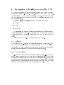
In section 2 an overview of dynamic modeling is presented | especially
wrt to OMT-methodology presented by Rumbaugh et al in [11] | and the
motivation for the development of the SCED system is discussed. Some
of the shortcomings of OMT's notation for scenarios are also discussed in
section 2.
The scenarios that can be edited and processed with SCED are somewhat
more elaborate than the scenarios used with OMT-methodology described in
[11]. Subscenarios and specifying repeated event sequences are described by
Koskimies in [7]. Some elements and features of SCED's scenarios have been
inuenced by 3L-diagrams which are used by Nokia Cellular Systems (NCS).
The 3L-diagrams are described in section 3. NCS has been an industrial
partner of the development project for the SCED system. They have given
us useful feedback about their usage patterns of a scenario editing tool in
a production environment and provided valuable commentary during the
development of SCED.
Section 4 describes shortly the internal structure of the rst implementation of SCED.
1
SCED includes support for generating state machines automatically for
participants in scenarios and for representing them graphically as state diagrams. The method used in the automatic synthesis of state machine is
based on Biermann's method described in [1] and is described in more detail
in section 5 and by Koskimies and Makinen in [8]
The features and capabilities of the SCED system are described in section 6.
Section 7 contains the user's guide for the MS-Windows implementation.
2
2 Dynamic modeling in OMT
State diagrams are a visual specication formalism for describing the behaviour, control, and interaction of a functional system. State diagrams have
been used for various purposes, ranging from the specication of a lexical analyzer in a compiler upto the behavioral description of a complex real-time
system. Here we consider state diagrams in a particular context, namely as a dynamic modeling technique in object-oriented analysis and design
(OOA/D).
In OOA/D area state diagrams are employed by several dierent methods, with slight variations. We will use the OMT method [11] as a guideline,
although the resulting system could be useful for other methods as well (and
indeed for entirely dierent applications making use of state diagrams or nite
automata). OMT consists of three modeling techniques: object modeling for
describing the static relations and properties of objects, dynamic modeling
for describing the behaviour of objects, and functional modeling for describing the input-output relations of operations. Of these models, OMT emphasizes the role of the object model | this part is relevant for all applications.
Dynamic modeling is needed for specifying the external behaviour of active
software like embedded real-time systems or interactive user interfaces. Since
most modern systems have components falling into these categories, dynamic
modeling is essential in many cases. Functional modeling plays only a secondary role in OMT; it is mainly used in computation-oriented applications,
like spreadsheet programs, compilers, engineering and design systems, etc.
OMT method is close to earlier methods like the ones proposed by Shlaer
and Mellor [12] and Coad and Yourdon [3]. OMT is slightly more systematic, trying to establish a clear connection from analysis to design. Since the
OOA/D eld is constantly evolving, new methods and revisions of the old
ones will surely emerge in the near future.
Most of the existing OOA/D techniques are supported by a tool providing
facilities for constructing the models and deriving actual code from the specications. The rst and second generations of these tools which are currently
in the market oer hardly more than specialized graphical editors for dynamic
modeling, with some modest consistency checking and code generation services (e.g. OMTool, Objectory, Paradigm+, Teamwork). This project aims
at the improvement of automated support for the dynamic model, presented
as state diagrams. Hence, eventually the result of this work is considered to
3
be part of a complete OOA/D CASE environment, although the prototype
system is designed to run stand-alone.
In the OMT method, the design of state diagrams starts with the construction of so-called scenarios. Note that scenarios are also included in
slightly dierent forms in other OOA/D methods; Jacobson et al [5] describe
them as interaction diagrams, Booch has included interaction diagrams in
the second edition of his OOA/D book [2].
A scenario is a sequence of events occurring during a particular execution of a system. Such a scenario is presented graphically as an event trace
diagram describing the order of sending certain events between objects. Scenarios are given rst for "normal" cases, and then for dierent kinds of "exceptional" behaviour. When a suciently complete set of scenarios exists,
they are transformed into a state diagram for each participating object. In
a sense, a scenario is an instance of a state diagram, describing an example
path in the state diagram; a state diagram is the union of all possible (usually
innite) scenarios.
The basic assumption behind the SCED system is that the construction
of scenarios, and the combining of the scenarios into a state diagram can
be supported by automatic tools far more than what is done by the current
systems. Presently automatic support is primarily directed to the editing of
state diagrams, but actually the work starts from the level of constructing
the scenarios, and it follows naturally that this phase could be viewed as
the main working environment: a state diagram is a logical consequence of
scenarios rather than an independent design target.
It seems that a state diagram can be | to a signicant extent | generated
automatically or half-automatically on the basis of representative scenarios.
On the other hand, the editing support for scenarios leads to clear advantages even without considering the automatic generation of state diagrams;
scenarios can be drawn using an attractive graphical tool in a standardized,
systematic way, additional information can be easily attached to the scenarios, scenarios can be made part of the automatic design environment like
other graphical specications, and scenarios can be easily included in the
(automated) documentation of a system.
4
Critique of OMT notation
The original notation for scenarios has certain drawbacks, especially when
being manipulated in a graphical editor.
1. Each "row" in the event trace table has exactly only one active object
(i.e. object sending the event) playing the essential role in that context,
but this object is not shown very explicitly; it can be found by looking
for an object column with a leaving arc. Indeed, in some situations,
the active object cannot be uniquely determined at all (if an event is
sent simultaneously to several objects, and the target objects are not
next to the sending one). Also note that the sending of an event to
two directions looks exactly the same as the crossing of an event arc
and an object line. In some situations it could be sensible to have an
event such that the target objects are more emphasized in the graphical
presentation.
2. Often a scenario has a logical structure which is not explicitly shown;
the OMT scenario notation describes the event trace on the lowest
possible level. E.g., a repetition of an event | or event sequence |
is shown simply by repeating the event arcs. In a way this is sensible;
explicit loops belong to a state diagram rather than to a scenario.
However, actually the user knows that certain events are part of an
iteration, and she should be able to express this knowledge. This is also
an essential piece of information for state diagram generation. Since the
main user interaction is supposed to take place in scenario construction,
it is natural that some information conventionally given in the state
diagram construction is transferred to the scenario specication phase.
3. An OMT scenario is completely unstructured statically. In practice,
however, it is likely that there are subscenarios appearing in several
scenarios, that one scenario is part of another, or that a scenario can
be naturally divided into parts that have clear, intuitive meaning. In
all these cases it would be helpful if a subscenario could be named
and "called" or "included" within another scenario. Again, this would
improve the generation of state diagrams.
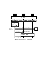
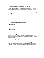
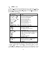
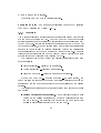
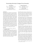
In the initial research plan Koskimies [7] presented a visual form for scenarios which specically addressed these problems. There the participants
5
are represented as columns having a certain width and an event sent by a
participant is clearly identied by a rectangular box drawn in the sending
participant's column. A received event is identied by a circle in the receiving participant's column. This format makes it very easy to visually identify
the events a particular participant sends or receives. An example diagram of
this format is shown in gure 1.
Figure 1: An example of modied scenario notation
However, in the rst implementation of SCED this format has not been
used, because the OMT-type notation was already widely used inside NCS
and it seemed somewhat dicult to convert to signicantly dierent notation. Especially, it looked problematic to use very long event names with the
modied notation, because the sending boxes of the events would have been
of unequal height thus making the scenarios visually hard to read. Alternatively, the long event names would have had to overow the sending box in
the event's direction. This didn't seem to be aesthetically pleasing, either.
Many of the problems discussed in the critique have been solved by making slight modications while preserving the essence of the OMT-notation.
6
E.g. a small rectangular box was added to the event at the sending participant's column thus making it evident which participant was the sending
one.
7
3 Description of 3L-diagrams used by NCS
NCS uses a particular type of scenarios for system and object behaviour
specication called 3L-notation. The 3L-diagrams are not based on OMTscenarios specied by Rumbaugh et al in [11], but the 3L-diagrams do contain
the OMT-scenarios as a subset even though the visual representations are
somewhat dierent.
3L-diagrams | scenarios | consist of the following elements:
Objects
Events
Comments
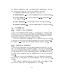
The scenario's name is shown inside a rectangular box which is extended
across all participant columns. The scenario name box is shaded to give it
a 3-dimensional look to visually distinguish from other types of comment
boxes.
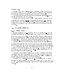
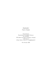
An example of an NCS-type scenario is shown in gure 2.
3.1 Objects
The objects in the 3L-notation are displayed as straight vertical lines. The
name of an object is displayed in a rectangular box at the top of the line
representing the object line. If a scenario extends across several pages, the
object names are displayed at the top of each succeeding page.
3.2 Guest objects
A 3L-scenario can also have some objects as visiting objects, i.e. objects that
are not really considered to be a part of the current scenario, but they are
involved in minor interaction with some of the scenario's events. These guest
objects are drawn as rectangular boxes on the right hand side of the scenario.
In all of the example scenarios there has been only one guest object, but there
seems to be no inherent reason why there couldn't be more.
8
TLA
KKL
DLE
LOCK KKL
Assumption:DLEs, RDXs and channels can be locked or unlocked.
Operator:
Select: DLE >>
State >> Lock.
repeated
for all ETD
M-SET (DLE) AdministrativeState=Locked
M-SET Conf
M-SET (KKL) AdministrativeState=Locked
-
All DLEs are locked, RDXs and
channels are disabled
M-SET Conf
Figure 2: An example of NCS type scenario
9
- ETD
3.3 Events
Events are displayed as horizontal lines originating from the sending object
and ending in an arrow which connects to the receiving object. The event's
name is shown directly above or below the event line. The name string
is a free-form text string which can also contain additional information in
an agreed-upon format, e.g. event's parameters. The drawing tool for 3Ldiagrams does not enforce any strict placement rules for names of the events,
i.e. the event names can be horizontally centered or shown in a specic object
column.
3.3.1 Specifying repeated events
A free-form text entry as repetition specication is often used in 3L-diagrams
as the number of repetitions is often not exactly known | or considered
unimportant | and it is informative to explain how the number of repetitions
is determined. Typically the repeat specication indicates that a message is
being sent to all objects of a certain class.
In 3L-notation, the descriptive text appearing at the left-hand side of the
repeated event sequence is the only visual indication that the sequence | or
a single event | is repeated several times.
3.4 Comments
There are two types of visually diering comment boxes used in 3L-diagrams.
Comments describing the current state of an object are displayed as rectangles with rounded corners. Other types of comments are shown as rectangular
boxes which can extend across several object columns when necessary.
10
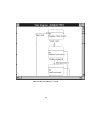
4 Overview of the implementation
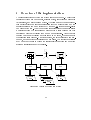
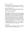
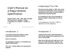
The general structure of the SCED system is shown in gure 3. The software
consists of three main components, scenario editor, state diagram generator
(synthesizer), and state diagram editor. Typically most of the user interaction is concentrated on specifying scenarios for the modeled system and the
generator is just a command activated by the user, i.e. it is not a user-visible
component of SCED. At any time during scenario editing the user can select
a participant from the scenarios and require that a state diagram for that
participant will be synthesized from one or more scenarios. After the state
diagram has been synthesized and it is shown in a window, the user can edit
the resulting state diagram. As of this writing, the layout algorithm is a simple one, and user editing is desirable in most cases. The editing capabilities
of STE enable the user to change the resulting layout; adding and removing
states or transitions is not yet possible.
#
#- PP
- l
l
)
" 6 ! ,,@@ "l -6 l !
SCE
-
SDG
STE
6 ZZ
6 ZZ
6
ZZ
ZZ
Z~ ?
? L
~Z
LL internal
L
L
L
internal LL
L
L
L
L
L
LL rep. LL LL L L internal L LL rep. LL
LL L rep. L
LL
LL
Figure 3: Overview of the SCED system
11
Development environment
SCED has been developed in | and for | the Microsoft Windows 3.1
operating environment. The tools that are being used for the development
work have been selected so that porting to Unix with OSF/Motif should
be possible with moderate eort. Strong dependency of the MS-Windows
environment has been avoided. However, the user interface for SCED in MSWindows environment will conform to MS-Windows programming guidelines
[9] and using SCED will be relatively straightforward for users with MSWindows experience. E.g. the standard MS-Windows methods are used for
selecting various on-screen entities and manipulating them by dragging.
The development tools that have been used are:
Borland C++ V3.1 | AT&T Cfront 3.0 "conforming" implementation
of the C++ language [4]
LEDA { Library of Ecient Data types and Algorithms class library
[10]. Portable across wide range of platforms; MS-DOS and several
Unix systems.
wxWindows { GUI library. Portable between MS-Windows, Windows
NT, Motif, Open Look.
Borland C++ provides an object-oriented layer to insulate the applications
programmer from direct access to MS-Windows API. This layer is called the
Object Windows Library (OWL) and it is included with the Borland C++ and
Application Frameworks package. However, the OWL is directly tied to Borland C++ environment, because a non-standard method is used to associate
C++ functions to MS-Windows message. OWL is not currently available with
other GUI environments besides MS-Windows. Furthermore, OWL doesn't
obviate the need to communicate directly with the MS-Windows API.
To support the possible necessity to port SCED to Unix/X-Windows
environment, and | more signicantly | to simplify the SCED's actual
development, a portable object-oriented GUI library | wxWindows | has
been used in the rst SCED implementation.
12
5 Automatic synthesis of state diagrams
In principle the problem of state diagram generation resembles the problem
of language inference. Basically, language inference means that a language
processor | say, a nite automaton | is constructed on the basis of a nite
number of example sentences belonging to the language. This is essentially
the same problem as the problem of generating a state diagram automatically on the basis of scenarios: a state diagram can be viewed as a language
recognizer, and a scenario can be viewed as an example sentence that should
be accepted by the state diagram; in other words, the object should realize the behavior given by the scenario. The connection between scenarios
and state diagrams are explained in more detail in section 7.7.2 and in [8].
However, there are special features in OMT state diagrams and also in the
exact formulations of the language inference problem that make it dicult
to directly apply the results in state diagram synthesis.
The synthesis method
There are two basic variations of the language inference problem: automaton
identication from requested data and automaton identication from given
data. Our problem is near to the latter one. However, it has been shown
in [6] that the problem of nding an automaton with minimum number of
states which agrees with the given data is NP -complete, and therefore computationally dicult. An algorithm solving this problem is given in [1]. This
algorithm is adopted to SCED for generating state diagrams automatically.
In spite of the exponential behavior of used algorithm it appears to be
practically feasible when the automatons are not too long and the algorithm
does not need to backtrack often. In OMT state diagrams are seldom very
large, because large state diagrams are hard to understand. It also seems that
in practice backtracking is not in heavy use, see [8]. Hence, in most cases
state diagrams can be generated quite quickly using Biermann's method
State diagrams generated using Biermann's method have a minimum
number of states. This property also raises some problems. For example,
the algorithm may merge together states which represent logically dierent
situations. It is dicult to detect these cases during automatic synthesis, because the nature of the problem is highly semantical. To avoid this problem
the following heuristical "ying visit"- rule was adopted: a trace item is not
13
allowed to be associated with an existing state if the trace both enters and
leaves this state with new transitions [8] (p. 23).
It turned out that the ying visit rule if often too strong; it may cause
the separation of states that were ment to me merged. Like mentioned in
section 2 scenarios usually represent normal cases and dierent kinds of exceptional behaviour. In other words, each scenario describes an example path
in a state diagram. In this case when scenarios are synthesized in a certain
order the ying visit rule may cause a separation of some states which would
not happen if the scenrios are synthesized in a dierent order.
Since state diagrams do not have diversied editing properties yet and
the use of the ying visit rule faces problems explained above, the user is
given a possibility to inuence the merge during the synthesis. So, the nal
decision of merging these ying visit states is given to the user.
In OMT state diagrams, a transition is usually associated with an event
name, possibly together with event attributes and additional actions or events
which are carried out when this transition is taken. Further, a transition can
have a guard, i.e. a condition that has to be satised when this transition
res. A state can be associated with a state name, entry and exit actions,
and a state activity. A state can also accept internal events, i.e. events
that cause an action to be performed without causing a state change and
so without causing the execution of entry or exit actions. Finally, states
can be concurrent or organized hierarchically sharing common transitions or
actions. Hence, OMT state diagrams dier considerably from the traditional
nite automata model. So, a pure Biermann's method is not sucient for
adopting these advanced modeling concepts of OMT to state diagrams in an
optimal way (decreasing the number of states and transitions). Most of these
concepts are not yet implemented. Investigating how these concepts can be
adopted automatically or semi-automatically | using the information given
in scenarios | belongs to future SCED development.
14
6 Functional description for SCED
Here the basic functionality of the SCED system is described | what features and activities are provided and supported by the software. The descriptions are expressed in general terms and the discussion of the actual
methods used while working with SCED is deferred to the user's guide part,
section 7.
6.1 Projects
SCED views a set of related scenarios and state diagrams as a project. In
the rst prototype implementation a project is simply dened as a directory
of the underlying le system and the set of scenarios and state diagrams
contained in that directory.
6.2 Building blocks for scenarios
Participants
Events
Comments
Subscenarios
Repetition specications
In this document we use mostly the term participant to describe the
entities being modelled. Usually participants are objects whose class is also
specied by the user. However, there are no restrictions built in SCED
to prevent the user from considering the participants as class-level entities
instead of objects.
6.3 Data dictionaries
The various elements of scenarios (objects, classes, events, etc.) are named
items. To simplify the specifying of names for new items as they are created
by the user, dictionaries containing the currently existing item names will be
maintained by SCED. When the name for a new item is required, the user
15
can select an existing name from the corresponding dictionary, and use that
name as such, or change the name in any necessary manner.
The following dictionaries are maintained by SCED:
Class dictionary | Names for all classes used in the current project.
Object dictionary | Names for all objects | i.e. participants | in
the current project.
Event dictionary | Names for all events in the current project.
Scenario dictionary | Names for all scenarios in the current project.
6.4 Participants
6.4.1 Creating a new participant
When a new participant is being created, by default, SCED expects the user
to supply both the object and class names for a participant, but either one
can be left out so that a participant can be specied as an object without a
corresponding class name, or with a class name only.
Object and class name dictionaries can be used to specify the names.
Object names must be unique within a scenario, but the same names can |
and usually do | exist in other scenarios within the current project.
6.4.2 Removing a participant
When the user has requested that an existing participant needs to be removed
from the current scenario, the various events and comments that are associated with the participant must also be considered by SCED. The events that
the participant sends to other participants, will be automatically removed,
as well as those messages where the participant to be removed is the sole
receiver.
Various comments that are associated with the participant will also be
removed from the scenario if they are not associated with any other participants.
If the destroyed participant was the last to belong to its class, the class
name can be purged from the class dictionary by the user.
16
6.4.3 Moving a participant
The column-wise placement of a participant within the current scenario can
be altered at will. SCED will automatically re-route and draw again all
events and comments that are associated with the participant to be moved.
6.4.4 Renaming a participant
Names for the participants in the current scenario can be edited as the user
wishes. SCED performs name validation and enforces uniqueness within
participant names of a particular scenario.
6.4.5 Changing participant's r^ole
A normal participant can be changed to be displayed as a guest participant.
Likewise, a guest participant can be changed to reappear as a normal participant. However, SCED does not use dierent visual outlook for normal vs.
guest participants and the distinction between guest and normal participants
is not particularly strong in other respects, either. Instead of implementing
special guest participants, a participant can be shrunk in vertical direction
so that it covers only a minimum height area to meet with all horizontal
event lines that the participant is taking part in. Several "guests" can then
be displayed in single participant column or they can be located in several
participant columns. A single participant can also consist of several noncontiguous segments. However, SCED does not allow dierent segments of
one participant to be located in several separate participant columns, i.e.
they must exist in a single column.
In all situations, an event can only exist as a horizontal line, i.e. two
participants can be participants in the same event only if at least parts of
their visual representations are on the level horizontally.
6.5 Classes
Classes are handled mostly automatically by SCED based on user editing
of class information attached to participants. Only purging of unused class
names from the class dictionary requires user interaction.
17
6.6 Events
6.6.1 Creating a new event
A new event can be specied to occur between two or more participants. An
event has one sending participant and one | or optionally multiple | target
participants.
6.6.2 Manipulation of events
The following operations are supported for changing the event information
using direct manipulation of the current scenario.
Adding a new target
Removal of one or more targets
6.6.3 Events' parameters
A parameter list can optionally be specied as a part of the event's name.
SCED doesn't place any syntactic restrictions on the format of parameter specications, but it is a recommended that a parameter list would be
specied as a comma-separated list of items included in parentheses.
6.6.4 Conditional events
An event can optionally be specied to be a conditional event. Like with
parameter information, no formal syntax is enforced on the condition specication, but SCED knows when a condition has been attached to the event
when the condition is enclosed in brackets and appended to the parameter
name. The condition should be placed after the optional parameter list, if
any, e.g.
Synchronize(3,factor)[inputOff]
6.6.5 Removing an event
A selected event can be completely removed. Note that if some of the participants are not active anymore, i.e. they are not senders nor targets of any
event, the participants are not removed from the scenario but they remain
in their current places.
18
6.7 Comments
The following commentary types are supported:
Plain comment text
State description
Action description
The various comment types are distinguished from each other by a text
label identifying the type of commentary text.
Note that a plain comment has currently no signicant meaning for
SCED, i.e. it is ignored in any further processing. State and action descriptions are used in state diagram synthesis and are described shortly in
the following sections.
Plain comment box can be extended across several participant columns.
If there are more than one participant attached to a comment, the attached
participants are visually marked within the comment box.
6.7.1 States
By attaching states to a participant the user can specify state names to be
used in a state diagram. Synthesis of state diagrams will consider only those
states of a participant which are followed by leaving events (or actions).
In this case the leaving event will be the action part of this state in state
diagram. With states attached to a participant the user can make sure that
certain states will not be merged in synthesis by giving them dierent names.
6.7.2 Actions
Actions of a participant represent leaving events with undened receiver participant.
6.8 Subscenarios
In the place of an event line, another scenario can be referenced. Such a
scenario is called a subscenario. Semantically a subscenario reference means
that the contents of the referenced scenario is included at the place of its
19
reference. Any scenario can be used as a subscenario, so a subscenario can
potentially also be used as an independent scenario.
When a subscenario inclusion is specied, the referenced subscenario does
not have to be an already existing scenario: the user can dene the actual
subscenario later, if desired.
6.9 Repetition specication
A repetition specication can be specied to include one or more event lines
| an event line may also be a subscenario.
The repetition specication can be one of the following:
+-character meaning one or more repetitions
*-character meaning zero or more repetitions
A numerical constant indicating the number of repetitions
Free-form text describing the nature of the repetition specication
A repetition specication can extend across several (consecutive) event
lines, i.e. those lines form a looping construct and are repeated as a group.
20
7 Using SCED
This document describes the features and usage of SCED for creating scenarios and synthesizing state diagrams for participants from one or more
scenarios.
The basic capabilities of the SCED system have already been discussed
in section 6, but user interface details are discussed in the following chapters.
SCED is a typical direct manipulation graphical object editor with a
graphical user interface. A pointing device (i.e. a mouse) is necessary for
working with SCED, even though MS-Windows in principle is usable with
plain keyboard interface.
7.1 SCED window structure and layout
Several scenarios and state diagrams can be opened for viewing and modication simultaneously. In the MS-Windows environment, the MDI (Multiple
Document Interface) user interface method is used for presenting the various windows, i.e. the child windows are attached to their parent | moving
automatically when the parent window is being moved around the screen |
and they can not extend beyond the parent window borders.
Each child window has both horizontal and vertical scrolling capability
supporting the construction of large scenarios and state diagrams.
7.2 Using SCED as an OLE server
SCED can be used as an OLE server application for both scenarios and state
diagrams, so that SCED documents can be embedded in and dynamically
linked to from other documents. Embedding or linking a SCED document
in another application's document is done by exporting the document to the
clipboard and selecting | in the other application | Paste for embedding or
Paste Link for linking the SCED document in the application's document.
Note that when SCED is run for the rst time, it will attempt to register
itself as an OLE server program in a database which is maintained by MSWindows. User will be notied of the registration process and its success.
21
7.3 Selecting items in a window
Selecting graphical items for manipulation (e.g. moving or deleting) in a
window is done using standard MS-Windows selection mechanisms. Single
item is selected by clicking the left mouse button when the mouse cursor
is on the desired item. More items can be added to the currently selected
set of items by holding SHIFT-key down when selecting new items. An
item can be "de-selected" from a set of selected items by holding down the
SHIFT-key while clicking the left mouse button on the selected item.
Meaning of an "item" depends on what kind of direct manipulation the
child window supports for its contents, but in general text items and various
graphic entities (lines, boxes, etc.) can be selected for manipulation.
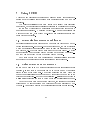
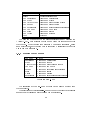
7.4 SCED menu structure
Here we will briey describe what commands/actions are available as selections from SCED menus.
Command
New
Open
Close
Save
Save as
Save all
Export
Print
Exit
:::
Action
Create a new scenario/state diagram
Open a scenario/state diagram le
Close a scenario/state diagram
Save scenario/state diagram (unnamed ) prompt for name)
Save scenario/state diagram (and name it)
Save all open scenarios/state diagrams
Copy child window to clipboard/metale
Print a scenario/state diagram
Exit SCED
Figure 4: File-menu
The File-menu commands in gure 4 are pretty much self-explanatory,
but Export-command is not standard in every MS-Windows application.
By selecting Export, the user can copy the contents of the currently active
child window to a Windows metale or to the clipboard for embedding into
other documents.
22
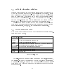
Command
Text
Scope
Cut
Copy
Paste
Clear
Action
Select text editing tool
Select scope for editing operations
Cut selected text to clipboard
Copy selected text to clipboard
Paste text from clipboard at cursor position
Delete selected text
Figure 5: Edit-menu
The Edit-menu commands of gure 5 are also quite standard for a MSWindows application except for the Text- and Scope-commands. The Edit
) Text-command selects the text editing tool to be used as the current tool.
The Edit ) Scope-command denes the scope for editing operations.
There are three alternatives:
Single: editing applies only to a single text eld (default scope).
Current: editing applies to all text elds in the current scenario with
the same text contents. This can be used e.g. to change in a single
editing operation the name of an event which occurs several times.
Project: editing applies to all text elds in the current project's scenarios with the same text contents.
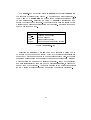
Command
Zoom in
Zoom out
Normal size
Refresh
Action
Enlarge child window view
Diminish child window view
Cancel zooming eect
Redraw window contents
Figure 6: View-menu
23
The Zoom-commands will magnify (Zoom in) or diminish (Zoom out)
the contents of current child window. The factor for magnication is 1.2.
With View ) Normal size the child window contents is returned back
to normal size again. Selecting the View ) Refresh will clear and then
redraw the child window contents. This is provided in case the screen update
will leave some "garbage" information on the screen. Hopefully there is no
need to use this command.
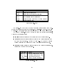
Command
New...
Open...
Close
Purge
Action
Create a new project
Open a project
Close current project
Remove unused dictionary entries
Figure 7: Project-menu
Selecting the Project ) Purge command will cause a dialog box to
be opened where the user can specify which of the various dictionaries are
purged and whether an automatic or manual purging will be done. If the user
requests manual purging she can select the names for purging from a listbox
which contains the names in the selected dictionary. If any of the selected
names is still referenced from some of the project's scenarios, it will not be
purged from the dictionary. Automatic purging is the default operation;
SCED will remove all unreferenced names from the selected dictionary.
24
7.5 Editing text
Editing text | like names for participants and commentary texts | is similar to text editing with other MS-Windows applications. In addition to
normal MS-Windows key assignments, several GNU Emacs-style editing key
conventions are recognized.
Key sequence
Left arrow / Ctrl-B
Right arrow / Ctrl-F
Up arrow / Ctrl-P
Down arrow / Ctrl-N
HOME / Ctrl-A
END / Ctrl-E
Ctrl-HOME
Ctrl-END
Ctrl-Left arrow / Esc B
Ctrl-Right arrow / Esc F
Ctrl-INS
Shift-INS
Shift-DEL
Ctrl-DEL
DEL / Ctrl-D
Backspace
Ctrl-K
Ctrl-O
Ctrl-T
Esc T
Return
Shift-Return
INS
Ctrl-L
Action
Move one character to the left
Move one character to the right
Move to the previous line
Move to the next line
Move to beginning of line
Move to end of line
Move to beginning of text
Move to end of text
Move one word to the left
Move one word to the right
Copy selected text to clipboard
Paste from clipboard
Cut selected text to clipboard
Clear selected text
Delete current character or selected text
Delete previous character or selected text
Delete to the end of line or kill line
Open a line
Transpose characters
Transpose words
End editing of current text
Force new line (in a multi-line text)
Toggle insert/overwrite mode
Redisplay
The most notable dierence between other text editors and SCED is that
<<ENTER>>-key is used to end editing. A newline can be forced by typing
<<SHIFT-ENTER>>-key . When editing text in a subscenario, comment,
state or action the text automatically wraps around at the right edge of the
25
enclosing box.
Holding down the <<SHIFT>>-key while using cursor movement key
commands will include the visited characters to selection area. Selecting
text can also be done by sweeping over the text with the mouse.
Text editing is currently supported only for scenario windows, i.e. names
in state diagrams can not be modied.
Clicking with the right mouse button while editing a text eld that is
maintained in a dictionary | i.e. object, class, or event name | will cause a
dialog window with a name list to appear. The user can select a name from
this list and the selected name will be inserted as the contents of the edited
text eld.
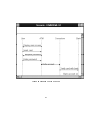
7.6 Scenario windows
7.6.1 Window layout
A scenario consists of one | actually two to be meaningful | or more
participants represented as vertical lines with the name of the participant
shown at the top of the line. Events occurring between participants are
shown as horizontal arrows extending from sending participant to receiving
participant. Commentary and subscenario specications can also be attached
to participants. These are described in more detail in later chapters.
Scenario windows have a header area were the names for currently visible
participants are displayed even when the window has been scrolled vertically
so that the names at the top of the participant columns are no longer visible.
The participant columns in a scenario are spaced so that they all are
separated by the same distance from each other. However, the width is
not xed and can be changed by the user | within limits dened by the
implementation and screen resolution.
Changing the participant distance can be done by selecting the second
participant from left while holding the <<CONTROL>>-key down. Then
the distance between participants will change as the second participant is
dragged closer to or farther from the rst participant.
Changing the margins | left or top | of a scenario can be done by
selecting the rst participant from left while holding the <<CONTROL>>key down. Dragging the participant will move the whole scenario within the
window.
26
Figure 8: Scenario window example
27
Similarly, the distance between event lines can be adjusted by dragging
the second event from top while holding the <<CONTROL>>-key down.
7.6.2 Tool palette
Using a tool palette provides an alternate method for interaction between the
user and the program in a graphical design environment. Instead of browsing
through menus to select activities | which is also possible to do with SCED
| the user can pick the required tool from the graphical tool palette which
is readily visible.
Figure 9: SCED Tool Palette
The following tools are included in the tool palette:
28
Tool
Select
New Participant
New Event
New Asynch Event
New Repeat
New Subscenario
New Comment
New State
New Action
Text
Action
General selection tool
Create new participants
Create new events
Create new asynchronous events
Create new repeat blocks
Create new subscenario specications
Create new comments
Create new states
Create new actions
Edit text
The user can change back to the general selection tool by pressing the
<<ESC>>-key . Each scenario window remembers what tool is in eect for
that window. Thus changing from scenario A to another scenario B, using
some another tool, and changing back to scenario A will restore the tool that
was in use with scenario A.
7.6.3 Scenario window menus
Command
Participant
Event
Asynch event
Comment
Repeat
State
Action
Subscenario
Action
Create new participants
Create new events
Create new asynchronous events
Create new comments
Create new repetition specications
Create new states
Create new actions
Create new subscenario specications
Figure 10: New-menu
The selections of the New-menu of gure 10 can also be eected from
the tool palette.
The selections in the Synthesize-menu of gure 11 control what scenarios
are used in synthesizing a state diagram for a participant.
29
Command
Current
Open
Project
Action
Participant in current scenario
Participant in all open scenario windows
Participant in all project's scenarios
Figure 11: Synthesize-menu
7.6.4 Participants
Creating a new participant After selecting the New Participant tool
| from the menu or tool palette | the user is expected to point and click
at desired location to place the new participant. If the current scenario is
empty, the new participant will be created as the rst participant regardless
of clicking position. As mentioned before, SCED will automatically pack
the scenario window area so that if a new participant is created between two
existing participants, existing participants to the right will automatically be
moved to the right.
SCED is placed in text editing mode so that the user can specify the
name for the new participant and its class.
The existing events and other row elements that will logically extend over
the new participant, will be redrawn by SCED.
Moving a participant The selected participant(s) can be dragged and
dropped to a new location within the current scenario. Participant area is
automatically packed by SCED after move operation.
Removing a participant The currently selected participant(s) can be
deleted by pressing the <<DEL>>-key .
While deleting the participant, all events that it sends to other participants and all of those events which have the participant as the sole target,
will also be deleted.
30
7.6.5 Classes
SCED maintains a class name dictionary based on what classes user has
specied for the participants. SCED suggests a two-line naming convention
for participants; the rst line species the name of the object, and the second
line species the class name in parentheses. The name in parentheses is recognized as a class name. This can be used to model the participant as a class,
i.e. by specifying only a single-line name which is enclosed in parentheses.
7.6.6 Events
An event is displayed as a horizontal arrow extending from a sending participant to one or more receiving participants. An asynchronous event is
displayed as a dashed line.
Creating a new event After selecting the New Event tool, the user
will select the sending participant, and move the mouse cursor to a receiving
participant where the dragging a mouse button will be clicked. Clicking
the right mouse button means that user will add more target participants,
clicking the left mouse button means that no more targets will currently be
specied for the event.
Placement of the event row is determined by the mouse cursor position at
the time of selecting the sending participant. SCED will be automatically
placed in edit mode to specify the new event's name.
Modifying events
Adding a new target: Added by clicking the right mouse button on a
new target participant on the same level with the event while selection
tool is in use.
Removing a target: Done in the same way as adding a new target,
i.e. the operation is a toggle.
Moving an event The selected event(s) can be dragged and dropped to a
new location within the current scenario. Event area is automatically packed
31
by SCED after move operation.
Events can only be moved in vertical direction.
Removing an event One or more event lines can be removed by selecting
them and by pressing the <<DEL>>-key .
7.6.7 Comments
Comments are displayed as various types of rectangular boxes which contain
the comment text inside the box. Each comment box can extend across
several participants to cover all of the participants that are associated with
the comment text. If there are intervening participants which the comment
text does not describe, the comment line area which covers those participants
is drawn so that it is easy to visually distinguish between the participants
that are associated with the comment text and those that are not. The exact
visual implementation will not be xed here but will be decided upon after
experimenting with various implementation methods.
The various types of commentary are visually distinguished from each
other as follows:
State description | displayed as a rectangle.
Action description | displayed as a rectangle.
Plain comment text | displayed as a rounded rectangle.
When a new comment | or state or action | is being created, the
user must click the left mouse button on an existing participant within the
scenario and the comment will be attached to the participant at the desired
location.
The following additional methods are supported for working with plain
comments:
Include participant for comment. Done by clicking the right mouse
button on the desired participant at the same horizontal level with
the comment box. Semantically this means that the commentary text
applies to all participants attached to the comment.
32
Exclude participant for comment, done the same way as including
a new participant to a comment.
7.6.8 Subscenarios
A sub-scenario is constructed like any other scenario, i.e. it exists as an
independent entity and it is not dierent in nature from any other scenario.
A sub-scenario reference is conceptually similar to an event line and it is
displayed as a rectangular box extending through all participant columns.
7.6.9 Repetition specication
Repetition specications are not implemented yet.
7.7 State diagrams
A state is an abstraction of attribute values of an object. In a system objects
stimulate each other causing state changes by sending and receiving events. A
change of state caused by an event is called a transition. A system consisting
of states of objects, events and transitions can be described as a state diagram.
In other words, a state diagram relates events and states.
In addition to values of objects, states can also represent actions. An
action is either a continuous activity or a sequential activity. A continuous
activity ends when an input event causes a state change. A sequential activity
ends when the operations are completed or an input event causes a state
change. In both of these cases action starts immediately after entering the
state. An action can also be associated with a transition, provided that
the action is instantaneous, i.e. the duration of an action is insignicant
compared to the resolution of the state diagram.
A guard can be associated with a transition. A guarded transition res
when its event occures, but only if the guard condition is true. An automatic
transition res when the action associated with the source state is completed.
An automatic transition with a guard res only if the guard condition is
true. If a state has more than one automatic transitions, but none of the
guard conditions are satised, then the state remains active until one of the
conditions is satised or until an event causes another transtion to re.
33
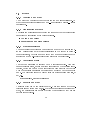
7.7.1 State diagram window layout
In SCED a state diagram is a directed graph in which nodes are states
represented by rounded rectangles including actions indicated within it by
the keyword "do:" and the directed edges are transitions. The possible names
In a state diagram the action of a state is directly the name of a of states
are written above the action parts separated by a horizontal line. Entry
actions, activities, internal events and exit actions are not yet implemented.
The colour of a state box describes the frequency of this state visited during
the trace: colours change from blue (low frequency) to red (high frequency).
Hence, the main paths of the state diagram will be eventually colored red
while more exceptional routes remain blue.
Synthesized state diagram will be drawn in active state diagram window
which is marked with "[ACTIVE]" in a title bar. Selection of state diagram
window activates it. The name of the participant for which the state diagram
is synthesized is also shown in a title bar in case state diagram window is not
empty.
State diagram specic menu In addition to other SCED menus the
following commands can be selected from the Tool menu:
Command Action
Join
Join selected states
Separate Leave marked states separated
7.7.2 Connections between scenarios and state diagrams
A state diagram can be synthesized for one participant at time. There can
be either a single scenario or several scenarios taking part to the synthesis. Synthesis is based on the information given in scenarios. All actions,
states and both leaving and entering events of the participant together with
subscenarios take part in the synthesis.
Synthesis algorithm does not care about extra spaces in names of scenario
events. There also may or may not be spaces in both sides of every special
character (e.g. brackets) in the event names.
All referenced subscenarios are processed; even if a certain subscenario
does not include the selected participant it may include a subscenario that
does.
34
Figure 12: State diagram window
35
States in a state diagram leaving event of a scenario participant. A
state without an action takes place when there are two arriving events in
succession (with no leaving event between them) in an event trace, both
of them corresponding to a transition (see below). So, an interval between
any two events is a state. The name of the state can be specied with a
state of a participant preceeding the leaving event or action as described
in section 6.7.1. Unnamed states will be merged (if possible) with the rst
possible state | having the same action part | with any or no state name.
Transitions in a state diagram Transitions in a state diagram corre-
spond to received events of a participant. An automatic transitions is denoted with the transition name default. An automatic transition takes place
in a state diagram when there are two leaving events in succession (with no
arriving event between them) in an event trace, both of them corresponding
to an action (see above). A guarded transition corresponds to a conditional
event, see section 6.6.4.
Note that from the receiver's point of view an event in a scenario denotes
a transition, while from the sender's point of view the same event denotes
an action. Possible conditions of leaving events will not be included in the
name of an action.
7.7.3 Synthesizing state diagrams
For a single scenario window state diagram synthesis for a certain participant can be done by selecting the participant and choosing Synthesize )
Current from the menu. Synthesis is made with the state diagram shown in
a active state diagram window. If there are no state diagram windows open
a new window is opened automatically. State diagram synthesis for a certain
participant of all open scenario windows can be done by selecting Synthesize ) Open from the menu. By selecting Synthesize ) Project the
user can include all or selected scenarios from current project in synthesis.
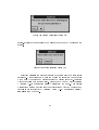
If synthesis algorithm nds any ying visit states (discussed in more detail
in section 5 and in [8]) it leaves them separated and colours them grey.
From the message box in gure 13 the user can choose whether she wants
to join some of these states or not. If user selects No all ying visit states
will be coloured white and left separated and synthesis will be completed.
Selecting Yes gives the user a possibility to selectively join some of these
36
Figure 13: Joining possibility dialog box
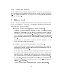
states. If Yes button is pressed the message box of gure 14 appears on the
screen.
Figure 14: Joining selection dialog box
Selecting Cancel completes synthesis and leaves all ying visit states
separated. After choosing OK user can choose the states she wants to join
with mouse by pointing and clicking inside the desired state box. Selection
will be cancelled with another click. Merge can be done by either pressing
<<ENTER>>-key or selecting Tool ) Join from the menu. This process
will continue as long as there are ying visit states which can be joined and
process is not interrupted by pressing <<ESC>>-key or selecting Tool )
Separate from the menu.
37
7.7.4 Editing state diagrams
In the current implementation state boxes can be dragged and dropped to
new locations but the overall structure of a state diagram cannot be changed,
i.e. new states/transitions can not be added and existing states/transitions
can not be deleted.
8 Future work
SCED provides a extensible framework where more automatic support for
dynamic modeling can be added. The following directions of functionality
are currently in planning stages:
Enhanced support for high-level state diagram constructs.
Currently the state diagrams generated by SCED consist of states,
actions, and transitions between states. These are the basic building
blocks of the OMT state diagrams. However, the full OMT notation is
much richer, providing support for e.g. conditional transitions, initial
and nal states, actions inside a state, nesting of states, and concurrency.
These should be supported by the state diagram editor and by the
automatic state diagram generation.
Consistency checks between scenarios and state diagrams.
When the user will be able to edit both scenarios and state diagrams
there should be automatic support for checking the consistency between
state diagrams and scenarios.
If the user makes changes to a state diagram, the system should check
that all of the scenarios can still be implemented by the modied state
diagram. When a scenario has been modied, the system should check
that the generated state diagrams still include the modied scenario.
In both cases, the system should infer the necessary modications which
will reect the user's modications on the other view | scenario, state
diagram | of the system.
The number of these modications should be as small as possible.
38
Improved automatic state diagram layout. Current layout algorithm is
very simple, the states are aligned on a single vertical column. This
method does not produce very natural looking state diagrams and in
case of a large number of states produces a diagram which is dicult
to understand and always requires user editing. Clearly a better layout
method is needed.
Automatic state diagram generation should preferably also take into
account the layout changes done by the user to previously generated
state diagrams for the same participant.
Acknowledgements
This work has been done as part of a TEKES funded project 4024/94.
References
[1] Biermann, A.W. and Krishnaswamy, R.: Constructing programs from
example computations , IEEE Trans. Softw. Eng. SE-2, 1976, p. 141 153.
[2] Booch, G.: Object-Oriented Analysis and Design with Applications, 2nd
ed , Benjamin Cummings, 1993.
[3] Coad, P., Yourdon, E.: Object-Oriented Analysis , Yourdon Press, 1990.
[4] Ellis, M., Stroustrup, B.: The Annotated C++ Reference manual .
Addison-Wesley, 1990.
[5] Jacobson, I., et al: Object-Oriented Software Engineering | A Use-Case
Driven Approach . Addison-Wesley, 1992.
[6] Gold, E.M.: Complexity of Automaton Identication from Given Data .
Information and Control 37, 1978, p.302-320.
[7] Koskimies, K.: A CASE Tool for Dynamic Modeling: Initial research
plan , internal document, 1992.
[8] Koskimies, K. and Makinen, E.: Inferring state machines from trace
diagrams , University of Tampere, Report A-1993-3.
39
[9] Microsoft Corporation: The Windows Interface: An Application Design
Guide . Microsoft Press 1992.
[10] Naher, S.: LEDA User Manual, Version 3.0 . Max-Planck-Institut fur
Informatik 1992.
[11] Rumbaugh, J., et al: Object-Oriented Modeling and Design. PrenticeHall, 1991.
[12] Shlaer, S., Mellor, S.J.: Object-Oriented Systems Analysis: Modeling the
World in Data , Yourdon Press, 1988.
40