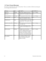
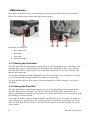
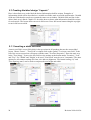
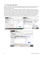
1
User Manual
Autolabel D43
This product is covered by patents WO/2009/105018, WO/2009/078797, with other patents pending.
Revision 2010-06-03A
Table of Contents
1 Introduction......................................................................................................................................4
2 Installation........................................................................................................................................5
2.1 Unpacking and Assembling the Machine.................................................................................5
2.1.1 Assembling the Machine...................................................................................................5
2.1.2 Connecting Cables............................................................................................................7
2.1.3 Connecting the Touch Screen............................................................................................8
2.1.4 Setting the Label Paper Width..........................................................................................8
2.1.5 Removing and Loading Rolls of Label Paper...................................................................9
2.1.6 Setting the Blow Applicator Label Length ....................................................................10
2.2 Test Print and Apply................................................................................................................11
2.3 Updating Articles and Label Layouts.....................................................................................11
2.4 Machine Settings ”Settings”...................................................................................................11
2.4.1 System Password.............................................................................................................11
2.4.2 Settings->Overview.........................................................................................................11
2.4.3 Settings->Printer.............................................................................................................12
2.4.4 Settings->Timing.............................................................................................................12
2.4.4.1 ”Conveyor speed”....................................................................................................12
2.4.4.2 ”Window start”........................................................................................................12
2.4.4.3 ”Window length”.....................................................................................................12
2.4.4.4 ”Apply delay”..........................................................................................................12
2.4.4.5 ”Trig block time”.....................................................................................................12
2.4.4.6 ”Blow delay”...........................................................................................................12
2.4.5 Settings->Adjust..............................................................................................................13
2.4.5.1 ”Print speed ”...........................................................................................................13
2.4.5.2 ”Print contrast” .......................................................................................................13
2.4.5.3 ”Label width ”.........................................................................................................13
2.4.5.4 ”Label length (mm)”...............................................................................................13
2.4.5.5 ”Print offset ”...........................................................................................................13
2.4.5.6 ”Fan speed”.............................................................................................................13
2.4.5.7 ”Blow time”.............................................................................................................13
2.4.5.8 ”Trig type”...............................................................................................................14
2.4.5.9 ”Trig polarity”.........................................................................................................14
2.4.5.10 ”Scale type”...........................................................................................................14
2.4.5.11 ”Righter time”.......................................................................................................14
2.4.5.12 ”Apply test prints”.................................................................................................14
2.4.5.13 ”Check max weigh”...............................................................................................14
2.4.5.14 ”Check min weigh” .............................................................................................14
2.4.5.15 ”Render side position”...........................................................................................14
2.4.5.16 ”Render top position”............................................................................................14
2.4.6 ”Settings->Network”.......................................................................................................14
2.5 Installation at the Production Line ........................................................................................15
2.5.1 Planning the System Installation ...................................................................................16
2.5.2 Selecting and Placing the Trig Sensor.............................................................................16
3 Daily Operation..............................................................................................................................17
2
Revision 2010-06-03A
3.1 Changing Labels.....................................................................................................................17
3.2 Select articles from the Article Register.................................................................................17
3.2.1 ”Refresh”.........................................................................................................................18
3.2.2 Sorting products..............................................................................................................18
3.3 Managing Articles and Layouts..............................................................................................18
3.4 Touch Screen Messages..........................................................................................................19
4 Maintenance .................................................................................................................................20
4.1 Cleaning the Print Head..........................................................................................................20
4.2 Cleaning the Print Roll...........................................................................................................20
4.3 Changing the Print Head.........................................................................................................21
4.4 Changing the Print Roll and Belt ...........................................................................................22
5 Article database and Layouts ”Editor”...........................................................................................23
5.1 Creating the label design ”Layouts”.......................................................................................24
5.1.1 Inserting a static text-field...............................................................................................24
5.1.2 Inserting a date-field.......................................................................................................25
5.1.3 Inserting a best before-field............................................................................................26
5.1.4 Inserting a variable text-field..........................................................................................27
5.1.5 Inserting a barcode..........................................................................................................27
5.1.6 Changing size and location of a text-field......................................................................28
5.1.7 Other tips ........................................................................................................................28
5.2 Creating an Article Register ”Articles”..................................................................................29
5.2.1 Choosing an Article to edit..............................................................................................29
5.2.2 Creating a new Article.....................................................................................................29
5.2.3 Copying an Article..........................................................................................................29
5.2.4 Deleting an Article..........................................................................................................29
5.2.5 EAN-code........................................................................................................................30
5.2.6 Price managing................................................................................................................30
5.2.7 Category-field.................................................................................................................30
5.2.8 Other fields......................................................................................................................31
5.2.9 Tips..................................................................................................................................31
6 File Managing.................................................................................................................................31
6.1 Necessary preparations...........................................................................................................32
6.2 Backup....................................................................................................................................33
6.3 Distribution of Layouts and Article Registers between printers.............................................34
7 Technical information ....................................................................................................................34
7.1 Performance............................................................................................................................34
8 Spare parts......................................................................................................................................35
9 Specifications.................................................................................................................................36
10 Declaration of Conformity...........................................................................................................37
3
Revision 2010-06-03A
1 Introduction
This document describes how to install, use and maintain the ”Autolabel D43” machine.
To get up and running as fast as possible, first read chapters 2.1 and 2.2. It is then possible to do a
first standalone test of the machine.
Next read chapters 2.3, 2.4 and 2.5 for detailed information on how to install and use the machine in
a production line, designing the label content, and creating the product database.
Chapter 3 contains information about the daily operation of the machine, while chapter 4 describes
the machine maintenance. For some operations a password is needed. Use ”0555”.
4
Revision 2010-06-03A
2 Installation
This chapter describes all the steps from unpacking the machine to initial testing, and full
installation in the production line.
2.1 Unpacking and Assembling the Machine
This section describes how to unpack the machine and to make it ready for a test print.
The workflow consists of the following steps:
1. Assemble the parts according to the drawing in section 2.1 below.
2. Connect the cables to the machine (trigsensor, applicator, network, touchscreen monitor and
touch panel cables, and status beacon).
3. Connect the cables to the touchscreen: TOUCH, VGA and 12VDC.
4. Connect power (110-250VAC, 50-60Hz) and compressed air (6-10 bar, dry and clean).
1. Warning: The machine must be connected with a grounded power-connector!
5. Set the label width using the label roll guide and the rewinder guide.
6. Load the machine with direct thermal labels.
7. (Blow operation) Calibrate the blow-applicator for the current label length.
2.1.1 Assembling the Machine
Assemble the machine according to the drawing below.
1) The procedure may vary slightly if you have the Autolabel marking station, or if you use
non-Autolabel accessories (e.g., a custom mounting stand).
2) The label guide discs (2 and 3) are delivered in a disassembled state. They are easy to
assemble without any tools. Press by hand to fit them together. No screws are needed.
3) The trig photosensor (4) in the picture shall just be electrically connected at this time. It will
be fully installed later when the machine is fitted to the production line.
5
Revision 2010-06-03A
Definition of the drawing:
1) D43 Print and Apply Machine
2) Label Rewinder Guide (inside)
3) Label Roll Guide (inside)
4) Trig Photo Sensor
5) Status Beacon
6) Stand Bracket
7) Touch Screen with Bracket
8) Stand Pillar
9) Stand Base
6
Revision 2010-06-03A
2.1.2 Connecting Cables
The following cables shall be connected to the machine. Please see the corresponding numbers in
the drawing below for the connection points:
Definition of the drawing:
1. All external cables to the machine shall be routed through the cable channel.
2. Power (110VAC to 250VAC, 50-60Hz). The machine must be connected with a grounded
power-connector!
3. Compressed air, 6 to 10 bar pressure, dry (no oil or water) and clean (no foreign particles).
The air is connected with a 6 mm tube and the enclosed air-connector. An external air filter
is recommended in order to keep the compressed air dry and clean.
4. Weighing equipment (optional). 9-pin RS232 connector. External weighing equipment can
be connected to this spare RS232 port.
5. Touchscreen – touch panel. 9-pin RS232 connector. Connected to the external touchscreen
(TOUCH connector). Required for touchscreen operation.
6. Touchscreen - monitor. 15-pin VGA connector. Connected to the external touchscreen (VGA
connector). Required for touchscreen operation.
7. LAN/network. RJ45 10/100 Mbit Ethernet connector. Required to use the internal product
database and layout editor.
8. CAN connectors (4x). Connect the Pluck or Blow applicator to any of the circular CANconnectors. Required for applicator operation. (Also optionally used for external add-on IO
boxes.)
9. Status beacon connector (optional). The optional status beacon is connected to the 4-way
terminal block.
10. Trig Photo Sensor (standard). The Trig Photo Sensor is connected to the 3-way terminal
block.
7
Revision 2010-06-03A
2.1.3 Connecting the Touch Screen
The touch monitor has three connections:
1. Screen. This connector is labeled ”VGA”.
2. Touch Panel. This connector is labeled ”TOUCH”. Please ensure that you connect this cable
to the correct connector on the D43 machine.
3. Power. The enclosed adapter (or other system power supply for the touch screen) shall be
connected to the connector labelled ”12V”.
4. The screen must be powered-up at the same time as the machine in order for the touch panel
to function properly.
2.1.4 Setting the Label Paper Width
The inner guide for the label roll and rewinder must be set for the current label paper width. This
must be done to ensure that the paper is centered throughout the machine, which affects the print
alignment. The settings are done by turning the label paper guides in relation to the label and
rewinder rolls.
The current setting is read according to the picture below, where the paper width is set to 80mm.
Definition of the drawing:
1. Label paper width (10x mm)
2. Label paper width (1x mm)
8
Revision 2010-06-03A
2.1.5 Removing and Loading Rolls of Label Paper
The drawing below illustrates the machine parts involved with removing and loading rolls of label
paper:
Definition of the drawing:
1. Printhead Handle
2. Rewinder Paper Pinch
3. Rewinder Roll
4. Rewinder Pinch Release
5. Inner Paper Guide
6. Outer Paper Guide
7. Label Roll
The figure on the right above illustrates how the paper shall be threaded through the machine.
Follow these steps to remove an installed roll of label paper:
a) Press the Rewinder Pinch Release (part 4). This collapses the rewinder paper diameter so
that it is easy to remove the old paper.
b) Remove the old paper from the Rewinder Roll (part 3). Clean the Rewinder Roll so that it is
free from label residue.
c) Remove the Outer Paper Guide (part 6)
d) Open the Printhead Handle (part 1)
e) Remove old label paper from the Label Roll (part 7)
9
Revision 2010-06-03A
Follow these steps to load a new roll of labels:
a) First follow the steps above to remove an existing label roll. The Printhead Handle shall be
in the open position, and the Outer Paper Guide shall be removed.
b) Change the Label Paper Width if needed, see section 2.1.4 for details.
c) Fit the new roll of labels to the Label Roll (part 7).
d) Pull/guide the paper around the flexible roller and up between the print roller and the open
applicator (see the threading illustration in the diagram above for details).
e) Pull about 50 cm of paper in front of the machine.
f) Pull/guide the paper back to the Rewinder Roll (part 3) and attach the end to one of the
Rewinder Paper Pinches (part 2). The paper end should be double folder for a secure
attachment in the pinch.
g) Attach the Outer Paper Guide (part 6). It shall be pressed against the label roll for a snug fit
to ensure minimum paper movement through the machine.
h) Close the Printhead handle (part 1) to the the closed position.
i) The machine will now automatically adjust the paper so that the media sensor is adjusted
and the label paper is positioned for a new printout.
2.1.6 Setting the Blow Applicator Label Length
For systems with a blow applicator, the label length must be correctly set in order for the applicator
to function properly. The label length is measured in the print direction. See section 2.2 for how to
do a ”TestPrint”.
Definition of the drawing:
1. Adjustment Handle.
10
Revision 2010-06-03A
Follow the steps below to set the blow applicator label length:
1. Load the machine with the current label paper (see section 2.1.5 above).
2. Place an object to be marked about 10 cm underneath the the blow-applicator.
3. Place your hand underneath the applicator. Press ”Start” and then ”Test Print” on the
touchscreen. See section 2.2 for details on how to do a testprint.
4. A label will be printed and applied to your hand.
5. Fold the printed label lengthwise and position it on the applicator as if it had been printed,
but not applied. It will be held in place by the applicator suction fan.
6. Turn the adjustment screw (part 1 in the drawing above) until the air nozzle inside the
applicator is centered in relation to the folded label. Remove the folded label.
7. Press ”Test Print” on the touchscreen to test the applicator setting.
8. Adjust the screw until the labels are applied with a repeatable accuracy of about 5mm.
2.2 Test Print and Apply
Follow these steps to print and apply a label:
1. Turn on the power and wait until the screen indicates ”OFFLINE”.
2. Press ”Products” on the touchscreen and select any product.
3. Press ”ONLINE”. The blow-applicator fan will start.
4. The machine is now ready to be trigged automatically using the photo sensor or manually by
pressing ”Test Print” on the touchscreen.
2.3 Updating Articles and Label Layouts
Please see chapters 5 and 6 for detailed information on how to change the articles in the internal
database and change or create new labels.
2.4 Machine Settings ”Settings”
There are a number of operator settings in the machine. They may vary slightly depending on the
specific factory configuration of your particular machine.
The settings can be found under the ”Settings” tab on the touch screen. A password is usually
required to view and change the settings.
2.4.1 System Password
The default system password is ”0555”.
2.4.2 Settings->Overview
In this screen you can view the system information, and also perform an application restart.
It is also possible to perform system maintenance (application upgrades, etc) by running scripts
supplied by Autolabel on an external USB flash drive attached to the control box. It is also possible
to see the internal air pressure. The pressure is measured after the internal regulator. Normal air
pressure is 5.0-5,8 bar.
11
Revision 2010-06-03A
2.4.3 Settings->Printer
In this screen you can set the machine orientation to get the proper rotation of your labels. The
labels are always designed ”upright” in the layout design program, and then rotated as needed in
this screen.
(The ”Print Quality Options” are disabled in this configuration, and can instead be changed on the
”Settings->Adjust” screen.)
The printhead temperature can also be monitored. It shall normally be slightly above the
surrounding temeratureon idle. During production it shall not exceed 70 °C.
2.4.4 Settings->Timing
In this screen you can set various machine timing parameters that normally has effect on the
placement of the label on the marking object.
2.4.4.1 ”Conveyor speed”
The conveyor speed does not affect the actual conveyor speed, instead it is used as a tool to see the
relationship between time and distance on the conveyor belt. When this setting is changed, it will
affect all the other timing settings, so it is easiest to set it first before the other timing settings.
2.4.4.2 ”Window start”
This setting has effect on how long time that must pass from a weight arrives from the scale to the
trigger signal is allowed to arrive. The setting is only active when ”trig type” is set to 0 or 1. Those
trig types are used when the printer is connected tro a scale.
2.4.4.3 ”Window length”
This setting determines during how long time from time window start an incoming trigger signal is
allowed. If a trigger signal is outside the time window the screen will display a warning ”Missing
trigger”. This setting is only available when ”trig type” 0 or 1 is set.
2.4.4.4 ”Apply delay”
This is the base delay from the trig input to the printing start. It is used to set the coarse label
position on the product, while the ”Label position” control on the ”Home” page (if active) is used
for fine grained position control.
Do not use values smaller than 50 ms.
2.4.4.5 ”Trig block time”
This setting is used to block new trig events for the specified time. This is useful when a single
product can generate multiple trig events. It is important to not set it too long, or the next product
will not be marked.
2.4.4.6 ”Blow delay”
This setting can be used to delay the blow application. It is normally never used since the blow
application works best when there is no delay.
12
Revision 2010-06-03A
2.4.5 Settings->Adjust
The tab "Settings" - "Adjust" mainly contains other non timing related printer settings
2.4.5.1 ”Print speed ”
Unit: mm/s. Can be up to 200 mm/s with good print quality. A lower setting (e.g. 160) can be
beneficial to achieve the highest print quality. This setting has effect on the label position. It can be
compensated by ”Apply delay”. See section 2..4.4.4.
2.4.5.2 ”Print contrast”
Unit: us. Autolabel D43 uses thermal print technology. Different label materials have different
sensitivities and the contrast can vary between different materials. Higher contrast means more
darker printouts. Worth thinking about is that high contrast can result in poor readability of the
printed barcodes. Normal levels are around 300-400 us.
2.4.5.3 ”Label width ”
Unit: mm. This affects how hard the rewinder roll will stretch the label paper. Appropriate values
are 20 – 120 mm. Normally the value shall be the same as the actual label width. When the printer
is used in floury environment 40mm shall be added to the actual label width if possible.
2.4.5.4 ”Label length (mm)”
Unit: mm. This affects how far the machine will scan for the gap between labels when closing the
print head. It will scan 20mm longer than this setting. It can be beneficial to trim this setting for the
specific labels used in order to avoid excessive paper loops during adjustment.
2.4.5.5 ”Print offset ”
Unit: 1/12 mm. Normally fixed at 26, does not need to be adjusted
2.4.5.6 ”Fan speed”
Unit: %. Used for blow applicators to control the label holder fan speed. A lower setting can be
desired for large labels so that they do not stick to the grille, while a higher setting can be used for
very small labels to secure them to the grille during the application process. Common values are 40
– 60%.
2.4.5.7 ”Blow time”
Unit: ms. Blow applicator blow time in milliseconds. Normally fixed at 80, does not need to be
adjusted.
13
Revision 2010-06-03A
2.4.5.8 ”Trig type”
This setting defines how the printer manages the trig sequence. Roughly it defines if a scale shall be
used. Three settings are describes below:
0:
Scale is used. No trigger is used. Incoming scale value starts print and apply.
1:
Scale is used. One trigger starts print and apply.
2:
No scale is used. One trigger starts print and apply.
2.4.5.9 ”Trig polarity”
Sets the hardware trigger polarity in order to set the label placement on the product relative to either
the product start (positive flank) or end (negative flank).
2.4.5.10 ”Scale type”
Sets the scale type if used.
2.4.5.11 ”Righter time”
Only for systems with a righter. Sets for how long the product shall be held still by the righter.
2.4.5.12 ”Apply test prints”
Test print labels can either be applied, or left in the unapplied position on the applicator grille. The
latter may be useful when changing the blow applicator screw setting.
2.4.5.13 ”Check max weigh”
For systems with external weighing equipment, this determines whether the product weights should
be checked against the limits in the article database.
2.4.5.14 ”Check min weigh”
For systems with external weighing equipment, this determines whether the product weights should
be checked against the limits in the article database.
2.4.5.15 ”Render side position”
This can be used to move the printout on the label, but should normally not be needed.
2.4.5.16 ”Render top position”
This can be used to move the printout on the label, but should normally not be needed.
2.4.6 ”Settings->Network”
This screen can be used to both view the current network address, as well as setting it to either a
dynamic (DHCP) address or a static IP address.
Normally only the IP address is used to access the printer from a web browser.
14
Revision 2010-06-03A
2.5 Installation at the Production Line
Autolabel D43 can apply labels to any side of your product. This chapter describes how to adapt the
print and apply system to the production line.
The diagram below illustrates the parts for a typical installation. Your exact installation may vary
according to your specific needs. Some parts must be supplied by the system integrator, e.g. the Trig
Photo Sensor mounting brackets.
Definition of the drawing:
1. D43 Print and Apply Machine
2. Label Rewinder Guide (inside)
3. Label Roll Guide (inside)
4. Trig Photo Sensor
5. Status Beacon
6. Stand Bracket
7. Touch Screen with Bracket
8. Stand Pillar
9. Stand Base
15
Revision 2010-06-03A
2.5.1 Planning the System Installation
The Print and Apply system can be mounted in many different ways. The barcode placement should
be considered when planning the system installation. The barcode quality is significantly better
when the barcode is oriented so that barcode lines are along the printing direction. The pictures
below shows some installation examples.
Bild 1
Bild 2
2.5.2 Selecting and Placing the Trig Sensor
A Trig Photo Sensor is normally used to detect the product to be marked and start the printout. We
recommend using sensors with a separate reflector to achieve the best possible system function.
Autolabel D43 is designed to be used with 24VDC PNP sensors.
16
Revision 2010-06-03A
3 Daily Operation
This chapter describes the daily operation of the machine.
3.1 Changing Labels
Please see chapter 2.1.4, 2.1.5 and 2.1.6 for details on how to change labels and set up the machine
for different label lengths and widths.
3.2 Select articles from the Article Register
To select the article to be activated at the start of production, click on the tab "Products". During the
"Recent" is the most recently used items. The tab "Standard" contains the articles which have not
received any specific category in the Article Register article. Tab "All" includes all items regardless
of category. In the illustration below the tab "Artiklar med pris" (Articles with price) was added in
the Article Register.
17
Revision 2010-06-03A
3.2.1 ”Refresh”
If a new article was added to or removed from the product register push the "Refresh" button to
update the list of products. This is not necessary if an existing article was changed, only if an item
has been added or removed.
3.2.2 Sorting products
In all tabs except "Last" products can be sorted by their different properties. Click on the property
you want the list to be sorted by. When selecting a second time so you can choose whether the list is
sorted in ascending or descending.
3.3 Managing Articles and Layouts
See chapter 5 for details on how to add articles to the Article Register and layouts to the printer.
18
Revision 2010-06-03A
3.4 Touch Screen Messages
The touch screen displays the status of the machine. There are a number of different warning and
error messages that can be shown:
Message
Type
Description
Status Beacon
Paper Low
Warning
Almost out of labels on the roll.
Green + Orange
Paper Out
Error
No labels left. The machine will
stop.
Red
Low air pressure
Warning
The air pressure is below 3 bar.
Green + Orange
No air pressure
Error
There is no air pressure to the
machine. The machine will stop.
Red
Printhead open
Status
The printhead handle is not in the Red
closed position. The machine will
stop.
Rewinder almost full
Warning
There is almost too much paper on Green + Orange
the rewinder roll.
Rewinder full
Error
There is too much paper on the
rewinder roll. The machine will
stop.
Missing trigger
Warning
A weight was received from
Green + Orange
external weighing equipment, but
there was no hardware trig input
within the selected time window.
This will be cleared automatically
after the next successful marking.
Date changed (select
new product)
Error
The date has changed, and any
date calculations on the current
label are no longer valid. The
machine will stop.
19
Red
Red
Revision 2010-06-03A
4 Maintenance
This chapter describes how the print and apply system must be maintained for proper operation.
Please refer to this drawing when reading the sections below:
Definition of the drawing:
1. Print Head Cover
2. Print Roll
3. Print Head
4. Printhead Handle
4.1 Cleaning the Print Head
The Print Head shall be cleaned approximately once per week depending on the environment of the
print and apply system. The Print Head will print with a lower quality when dirty, and it will also
detoriate faster if there is label residue stuck to the head which can cause excessive heating of the
thermal dots in the head.
To clean the Print Head, open the Printhead Handle. The Print Head is now accessible for cleaning.
It is best cleaned with isopropyl alcohol (also known as isopropanol).
The Print Head can also easily be removed from the machine for offline cleaning, see section 4.3
for details.
4.2 Cleaning the Print Roll
The Print Roll shall be cleaned approximately once per week depending on the environment the
print and apply system is placed in. The roll has a lower friction when dirty, which affects the
printout, print quality, and possibly the application. It can also increase the wear and tear of the print
roll, leading to a shorter life span.
To clean the Print Roll, open the Printhead Handle. The Print Roll is now accessible for cleaning. It
is best cleaned with soap and water, but isopropyl alcohol (also known as isopropanol) can also be
used. The Print Roll can also easily be removed from the machine for offline cleaning, see section
4.4 for details.
20
Revision 2010-06-03A
4.3 Changing the Print Head
The Print Head is a replaceable part that has an expected life of 150 km in a normal environment.
When the Print Head is worn out it will have one or more thin white stripes along the print direction
where the black print marks are missing on the label.
Follow these steps to change the Print Head:
a. Remove the Print Head Cover by grabbing the ribbed part and pulling it away from the
machine.
b. Disconnect the two cables that are attached to the Print Head. The machine can be left
powered on during this operation.
c. Move the Printhead Handle to the open position.
d. Disengage the Print Head by pulling it from the machine. No tools are needed since it is
only attached with a magnet.
e. Install a new Print Head. It should snap into place when it is in the correct position.
f. Place the Printhead Handle in the closed position. The machine will calibrate the media
sensor and feed the label paper to the starting position.
g. Connect the two cables to the Print Head.
h. Snap the Print Head Cover into place.
21
Revision 2010-06-03A
4.4 Changing the Print Roll and Belt
The Print Roll is a replaceable part. It has an expected life of 600 km or 2 years during normal
conditions. The Belt should be replaced at the same time as the Print Roll.
Refer to this diagram during the operation:
Definition of the drawing:
1. Service Lever
2. Belt
3. Print Roll
Follow these steps to change the Print Roll and Belt:
a. Remove the large front cover on the right of the machine. It is at the same end as the Print
Roll. It shall be pulled from the machine, and it is only attached by friction. There are
grooved surfaces for better traction.
b. Near the Belt there is a small black Service Lever (part 1 above) that must be pushed to the
end position at the same time as the Printhead Handle is moved to the service position
(marked by a wrench on the front of the machine).
c. Remove the Belt from the geared Print Roll wheel.
d. Pull out the Print Roll.
e. Remove the Belt from the geared motor wheel.
f. Place the new Belt around the geared motor wheel. Check that the Belt is not on top of the
motor wheel side walls.
g. Push in the new Print Roll.
h. Place the Belt around of the geared Print Roll wheel.
i. Move the Printhead Handle in the closed position. WARNING: The motor will start to
turn automatically! Keep away from moving parts!
j. Check that the Belt moves smoothly during the adjustment cycle.
k. Push the front cover back onto the machine.
22
Revision 2010-06-03A
5 Article database and Layouts ”Editor”
This chapter describes how to determine what should be printed, ie how to build up the look of the
print out, and how an article database is built up. Software for making these changes is installed in
the printer and accessed via the ”Editor”-tab on the main menu. To do this a standard keyboard and
a mouse may be connector directly to the printer, but for continuous operation the web-connection
is preferred. Follow the procedure below (see image below):
1. Se the printer is connected to a network / router.
2. Find the assigned IP address in the touch screen under tab ”Setup-Network”
3. Connect a computer to the same network as the printer and open a browser.
4. Write the IP number directly into the address bar with bullets, for example: ”123.45.6.78”.
5. You have now opened the printers web browser.
6. Click on ”Touch screen contents” to remotely control the printer. It may take a while for
touch-screen image to show up. The used computer must have support for Java. This may be
downloaded on ”www.java.com”.
7. When touch screen shows up, click on the tab ”Editor”.
8. You will find the tabs ”Articles” and ”Layouts”. See section 5.1 for ”Layouts” and 5.2 for
”Articles”.
23
Revision 2010-06-03A
5.1 Creating the label design ”Layouts”
Here is described were on the label the desired information shall be written. Examples of
information which will be described are: variable text fields, static text fields and barcodes. Variable
fields are fields that do not always contain the same text or number. Variable fields are blue in the
editor. Static text is black. Chapter 5.2 describes how to choose what information should be written
for each article. The layout editor can run in full screen. Press full screen button along the top right
to run in full screen mode.
5.1.1 Inserting a static text-field
A static text field is a text field which is always written in all products that use the current label
layout. Choose "Insert" - "Text Field" or simple click on the symbol 'T' to insert a text field. To the
left of the screen a menu bar will appear with the name "Text Box Properties". Enter the static text
in the "Text String". To move the text field, use the settings at the bottom under "Location", "Left"
and "Top". For "Width" and "Height" to be used, "Line break" must be set to "Automatic".The other
options are all common settings for fonts, size and text alignment. "Horizontal scaling (%)" and
"Line Spacing (mm)" can be used to compress the text height and width.
24
Revision 2010-06-03A
5.1.2 Inserting a date-field
A variable date field can for instance be manufacturing date. This field contains the current date. In
addition to this, the expression can be adjusted so that the clock turns to tomorrow's date at a
different time than at 24:00.
Follow the principle 5.1.1. Place your cursor in the "Text String" where you want the date to be
inserted. For instance, after the static text you have written (it is possible to mix static and variable
text). Choose "Insert variable". Then select "Name" - "Date" – "Manufacturing date" - "Production
start date / time". You may now select which date-format you prefer. Select the desired format. If
you want to change a standard format it can be done in the "Advanced features". Otherwise press
'OK'. In the "Advanced Features" you can select when you want the clock to turns to tomorrow's
date. This is shown in the bottom of the picture. In the "Variable Expressions", the figure for
"hours" can be changed. If the figure eight is used, the clock strikes on to tomorrow's date at. 16:00.
25
Revision 2010-06-03A
5.1.3 Inserting a best before-field
A "best before" field is a variable text field containing the sum of the current date and durability of
the article. In addition to this, the expression can be adjusted so that the clock turns to tomorrow's
date at a different time than 24:00. The durability for an article is set in the article database and does
not need not be set in the layout editor. Variable fields are fields that do not always contain the text
or number. These are blue in the editor.
Follow the principle 5.1.1. Place your cursor in the "Text String" where you want the date to be
inserted. For instance, after the static text you have written (it is possible to mix static and variable
text). Choose "Insert variable". Then select "Name"- "Date" - "Best before" - "Best before date /
time". You may now select which date-format you prefer. Select the desired format. If you want to
change a standard format it can be done in the "Advanced features". Otherwise Press 'OK'. In the
"Advanced Features" you can select when you want the clock to turns to tomorrow's date. This is
shown in the bottom of the picture. In the "Variable Expressions", the figure for "hours" can be
changed. If the figure eight is used, the clock strikes on to tomorrow's date at. 16:00.
26
Revision 2010-06-03A
5.1.4 Inserting a variable text-field
A variable text-field is a text field whose contents is determined in Article Register (they are blue in
the editor). Some fields that are used frequently are predefined in the editor, such as product
contents, weight, price and package variant. If these are not sufficient, there are ten extra-fields
which are also represented in the Article Register. These may be used for any information. Non
filled fields in the Article Register will become empty on the label. Boxes "Price", "weight" and "kg
Price" are interconnected. For example, if a "Kg Price" is added, the value will be calculated by
using the "Price" and "Weight" information in the Article Register.
Follow the principle 5.1.1. Place your cursor in the "Text String" where you want the variable to be
inserted. .For instance, after the static text you have written(it is possible to mix static and variable
text). Choose "Insert variable". Then select 'Name' - 'Database Fields'. Then select the desired
database field.
5.1.5 Inserting a barcode
Select "Insert" -1D/2D barcodes and select the barcode you want to insert. A menu bar will appear
to the left with the name "Barcode Properties." Choose the bar code location and size. Contents of
the barcode (eg EAN-code) are defined in Article code.
27
Revision 2010-06-03A
5.1.6 Changing size and location of a text-field
Simple click on the text box to be affected. At the bottom of the menu bar under "Text Field
Properties" it is possible to influence the location and size of the text box. To be able to change the
size, line break must be set to "automatic".
5.1.7 Other tips
28
•
It is possible to mix static text with variable text.
•
By using variable text-fields, the same layout may often be used by many articles. This may
simplify the handling of articles.
•
Different parts of a text field can have different fonts and font sizes. This often makes it
possible to use one text-field instead of two or more.
•
The variable line spacing and the horizontal scaling can often be used to get more text
without having to reduce the font size.
•
Some fonts are more readable than others using a small font size. Please test it before use.
•
When flowing text, be sure to check that the article with most text can fit in the text box.
Revision 2010-06-03A
5.2 Creating an Article Register ”Articles”
The Article Register is located under the tab ”Editor”-”Articles”. Here are all the information
located required to label the different articles.
5.2.1 Choosing an Article to edit
To change the contents of an article, an article must be selected. This is done through the list of
"Article ID". See picture below. Select the article you want to manage. If you don´t know the
article-id for a certain article it may help to search under "Products" where you can sort by various
properties of the articles.
5.2.2 Creating a new Article
Select "New" and fill in the fields to be used.
5.2.3 Copying an Article
Select "Copy" if a new article is based on an existing article. Only the new article-id number must
be filled in. Preferably given a new name. Then press "Save".
5.2.4 Deleting an Article
Press ”Delete”. Then press ”Yes”. The Article is now deleted.
29
Revision 2010-06-03A
5.2.5 EAN-code
Here the EAN-code for Articles are defined. There are 12 figures to be provided. The 13th is a
check digit calculated automatically.
If the EAN-code shall contain a price, start the EAN-code with 20. The printer will then
automatically use the ”Price”-variable for the barcode.
If an EAN-code shall contain the product-weight, start the EAN-code with 23. The printer will then
automatically use the scale-weight or the ”Weight”-variable defined in the Article Register.
5.2.6 Price managing
In the "Price"-field only the figures shall be filled, for example, "15.90". Weight is also defined by
numbers only. The unit is grams. The units may be written using the extra-fields.
5.2.7 Category-field
The field "Category" has special meaning. This is used to categorize articles under "Products"
tab. If, for example, "Artiklar med pris" (Articles with price) is filled in to the "Category" field, then
a tab named ”Artiklar med pris” will show up under the "Products" tab. This can simplify the
management of many articles
30
Revision 2010-06-03A
5.2.8 Other fields
The field "Name" is the name of the Article in the Article list under "Products" tab. This name will
not appear on the printout. The name can contain information that simplifies the choice of Article.
The field "Description" is the text-string that end up on the label if the variable "Description" has
been added to the label.
"Extra" fields can contain both text and numbers. These can be used completely free. For example,
units can be added in an extra field. If the "price" used by certain items and where you want to use
"EURO" after the price, but price is not used by all articles, the unit "EURO" can be added in an
extra field.
5.2.9 Tips
•
Speed up the search among many article ID's by finding the ID by looking under the
"Products" tab.
•
Use additional fields for units such as "EURO".
•
Use the "Name"-field to provide a descriptive name for an article that makes it easy to find
in the list. The name will not appear on the printed label.
6 File Managing
This chapter discusses how to backup Labels, Article Register, Settings, and any customer-specific
functions, but also how to distribute these files between multiple devices. It is these files that
distinguish a factory default printer from a printer ready to be installed on a production line.
With a recent backup, it is possible to ensure prompt up production at a potential problem with the
computer-unit. This could then quickly be replaced and loaded with the saved files.
Distribution of such files between different printers on a network makes it easy to maintain the
Article Register on one printer and then distribute it to other printers.
31
Revision 2010-06-03A
6.1 Necessary preparations
In order to implement backup and distribution of the files necessary, a computer must be connected
to the network used by the printer to be serviced. To access the relevant files in the printer, the
program "Filezilla" must be installed on your computer. Filezilla can be downloaded free online at
the following link: http://filezilla-project.org/download.php
Filezilla helps you to access the internal file system of the printer/printers. Before this can be done
you must have the IP address of the printer that should be handled. IP address is found via the
printer's touch screen in "Settings" – "Network". The password is "0555".
When "Filezilla" is installed and running:
1. Select "File" – "Location Manager" - "New Location". Enter an appropriate name for the
connection to the printer you must connect to. For example: "Line Printer 12".
2. In the "Host", enter the IP address, ex. "123.45.6.78".
3. Select server type "SFTP - SSH File Transfer Protocol".
4. Choose Login type: "Normal".
5. Enter user: ”autolabel".
6. Enter password "auto".
7. Leave the box for "Account" empty.
8. Press the "Connect".
32
Revision 2010-06-03A
Once the connection is successful you will get the file system on your local computer to the left
under "local site". The file system on the connected printer is to the right under "Remote Location".
The files to be handled in the printer can be found under the directory "home/auto
label/userdata/system". There are at least two files: "settings.cfg" and "db.sqlite". The file
"settings.cfg" contains all the settings. These usually distinguish between different printers. The file
"db.sqlite" includes Article Register and Layouts. These can often be shared between several
printers. If the current printer has customized features those are described by a file with the
extension ".py".
6.2 Backup
Make preparations in 6.1. Connect to the printer. Select all the files in the directory
"home/autolabel/userdata/system" and download them to the local computer. The files will then be
saved in an appropriate way. A new computer-box can then be updated to a replacement box for a
specific printer by the saved files "settings.cfg", db.sqlite "and possibly a file with the suffix".py”
from the specific printer.
The new files are used by the printer after reboot.
33
Revision 2010-06-03A
6.3 Distribution of Layouts and Article Registers between printers
It is preferable to make changes to Layouts and the Article Register on a specific
printer. Subsequently, these changes are distributed appropriately to other printers. Layouts and
Article Registers are stored in the file "db.sqlite". It is probably this file that is appropriate to
distribute. The file "settings.cfg" contains all machine-specific settings made under the tab
"Settings".
To implement the distribution, do the preparations in section 6.1. Connect to the printer where the
latest information is available (the master-printer). Download the files to be distributed. Then
connect to the printer to receive the new information. Replace the files on this printer to the local
files from the master-printer. You can save different types of files. "cfg" and ". sqlite" on the
printer. It is only the ones named "settings.cfg" and "db.sqlite" that are used.
The new files is used by the printer after reboot.
7 Technical information
7.1 Performance
The printer works according to the following procedure:
1. Prints out the entire label.
2. Feeds 15 mm +length of the label gap to get the label on the applicator.
3. Reverses 15 mm + label gap back to the start.
When blow-applicator is used, the printer must wait between 2 and 3 of a total of 100 ms. Of those,
80 ms are used to let the label arrive on the applicator before the apply pulse starts. Thereafter, the
printer is waiting for another 20 ms before the start of reversing to avoid remains of glue making
label accompanying the back-paper back into the printer.
The table below is based on a label gap of 2 mm. External factors such as trigger time can degrade
the overall performance.
Label length(mm)
Applies/minute (D43-Blow)
34
30 35 40 45 50 55 60 65 70 75 80 85 90 95
99 95 91 88 85 82 79 77 74 72 70 68 66 64
Revision 2010-06-03A
8 Spare parts
For spare parts contact your local Autolabel dealer or contact Autolabel directly:
Telephone: +46 31 743 47 22, email: info@autolabel
Autolabel AB, Ebbe Lieberathsgatan 30, SE412 65 Göteborg, homepage: http://www.autolabel.se
Article number: S100083
Name: FEMALE CONNECTOR
Article number: A100024
Name: PNEUMATIC BLOCK COMPL.
Article number: P100132
Name: COVER REAR
Article number: E100002
Name: POWER SUPPLY.
Article number: P100125
Name: COVER FRONT
Article number: A100006
Name: LABEL ROLL GUIDE
Article number: A100027
Name: LABEL ROLL GUIDE INSIDE
Article number: P100116
Name: COVER HEAD PROFILE
Article number: A100029
Name: LABEL REWIND GUIDE INSIDE
Article number: A100011
Name: PRINT HEAD 300dpi 4” COMPL.
Article number: A100093
Name: PRINT ROLL AND BELT COMPL.
Article number: A100019
Name: CPU UNIT COMPL.
35
Revision 2010-06-03A
9 Specifications
Printing Technology
Direct Thermal
Label Size (WxH)
D43-blow: 35x35 to100x100 mm.
D43-tamp: 20x15 to 120x150 mm.
D43-wipe: 20x15 to 120x150 mm.
Available Printing Area
100,0%
Resolution
300 DPI
Printing Speed
Up to 200 mm/s
Barcode Support
Yes
International Alphabets
Yes (Unicode)
Application Technology
Compressed Air (Blow Applicator), Wipe/Vacuum
(Pluck)
Application Speed
Up to 99 applications/minute
Application Distance (Blow Applicator)
Up to 150 mm
Outer Dimensions
532x360x425 mm
Maximum Label Roll Diameter
300 mm
Label Roll Inner Diameter
76 mm
Label Roll Winding
Labels Placed on Outside of Paper
Computer Platform
Mini-ITX 170x170 mm
Operating System
Linux
Communication
LAN, USB, CAN, RS-232, WLAN(option)
Operating Temperature
+5°C to +40°C
Humidity
20 to 85%
Power Supply
110-250 VAC; 50/60 Hz
Compressed Air
6 bar, dry and clean
36
Revision 2010-06-03A
10 Declaration of Conformity
37
Revision 2010-06-03A