1
Operators/Parts Manual
3-Point Solid Stand Drills
Stand Up Markers
Manufacturing, Inc.
P.O. Box 5060 ● Salina, Kansas 67402-5060
!
© Copyright 1999 Printed 8/19/04
Read the Operator’s manual entirely. When you see this symbol, the subsequent instructions and warnings are serious - follow without exception. Your life and the lives of
others depend on it!
113-324M
General Information
Important Notice
Great Plains Manufacturing, Inc. provides this publication “as is” without warranty of any kind, either expressed or implied. While every precaution has been
taken in the preparation of this manual, Great Plains
Manufacturing, Inc. assumes no responsibility for errors or
omissions. Neither is any liability assumed for damages
resulting from the use of the information contained herein. Great Plains Manufacturing, Inc. reserves the right to
revise and improve its products as it sees fit. This publi-
cation describes the state of this product at the time of its
publication, and may not reflect the product in the future.
Printed in the United States of America.
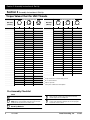
For your convenience, record your Serial Number, Model Number and the Date Purchased in the spaces provided below. Have this information available when
calling your Great Plains Authorized Dealer.
This Operator’s Manual applies to the Stand Up Markers for:
Part #
Description
Drill
113-124A
12’ Dual Hydraulic Marker 12’ 3-Point Solid Stand Drill
113-124A
14’ Dual Hydraulic Marker 14’ 3-Point Solid Stand Drill
113-124A
15’ Dual Hydraulic Marker 15’ 3-Point Solid Stand Drill
113-125A
20’ Dual Hydraulic Marker 20’ 3-Point Solid Stand Drill
113-127A
14’ Dual Hydraulic Marker 27’ 3-Point Solid Stand Drill
113-138A
30’ Dual Hydraulic Marker 30’ 3-Point Solid Stand Drill
Owner’s Information
Name: _____________________________________
Address ____________________________________
City________________ State ____ Zip ___________
Phone_______________________
Phone ______________________
Serial Number ________________
Model Number ________________
Date Purchased _______________
Name of Dealership ___________________________
Dealer’s Name _______________________________
Address ____________________________________
City________________ State ____ Zip ___________
113-324M
Great Plains Mfg., Inc.
3/19/03
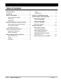
Table of Contents
Using this Manual . . . . . . . . . . . . . . . . . . . . . . . . . . 2
Hinges . . . . . . . . . . . . . . . . . . . . . . . . . . . . . . . 6
Introduction . . . . . . . . . . . . . . . . . . . . . . . . . . . . . . . 2
Disk Bearings . . . . . . . . . . . . . . . . . . . . . . . . . . 6
Section 1 Safety Rules . . . . . . . . . . . . . . . . . . . . . . 3
Section 5 Troubleshooting Guide . . . . . . . . . . . . . 7
General Operation & Repair . . . . . . . . . . . . . . . . 3
Section 6 Marker & Disk Assemblies . . . . . . . . . . . 8
Transporting . . . . . . . . . . . . . . . . . . . . . . . . . . . . 3
Folding Hydraulic Marker
{12’, 14’, & 15’ Drills} . . . . . . . . . . . . . . . . . . . . 8
Safety Decals . . . . . . . . . . . . . . . . . . . . . . . . . . . 3
Section 2 Assembly Instructions & Set-Up . . . . . . 4
Folding Hydraulic Marker
{20’, 27’, & 30’ Drills} . . . . . . . . . . . . . . . . . . . 10
Torque Values Chart for UNC Threads . . . . . . . . 4
Marker Disk Assembly . . . . . . . . . . . . . . . . . . . . 12
Pre-Assembly Checklist . . . . . . . . . . . . . . . . . . . . 4
Section 7 Hydraulics. . . . . . . . . . . . . . . . . . . . . . . . 14
Installation Instructions . . . . . . . . . . . . . . . . . . . . 5
Section 3 Operating Instructions . . . . . . . . . . . . . . 5
Bleeding of the Hydraulics . . . . . . . . . . . . . . . . . . 5
Marker Transporting . . . . . . . . . . . . . . . . . . . . . . 5
Single Marker Hydraulics
{15’ & 20’ 3-Point Drills}
14
Dual & Single Marker Hydraulic
{27’ & 30’ 3-Point Drills} 1 . . . . . . . . . . . . . . . . . 6
Section 4 Maintenance & Lubrication . . . . . . . . . . 6
Dual Marker Hydraulics Used With
CDH, CPH, & CC . . . . . . . . . . . . . . . . . . . . . . 18
General Maintenance . . . . . . . . . . . . . . . . . . . . . 6
Selector Sequence Valve {810-006C} . . . . . . . . 20
Storage . . . . . . . . . . . . . . . . . . . . . . . . . . . . . . . . 6
Lubrication . . . . . . . . . . . . . . . . . . . . . . . . . . . . . . 6
3/19/03
Great Plains Mfg., Inc.
113-324M
-1
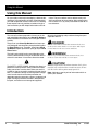
Using this Manual
Using this Manual
For your safety and to help in developing a better understanding of your equipment we highly recommend that
you read the operator sections of this manual. Reading
these sections not only provides valuable training but
also familiarizes you with helpful information and its lo-
cation. The parts sections are for reference only and
don’t require cover to cover reading. After reviewing your
manual store it in a dry, easily accessible location for future reference.
Introduction
This manual has been prepared to instruct you in the
safe and efficient operation of your Stand Up Markers.
Read and follow all instructions and safety precautions
carefully.
The parts on your Stand Up Markers have been specially designed and should only be replaced with genuine Great Plains parts. Therefore, should your Stand
Up Markers require replacement parts go to your Great
Plains Dealer.
The right hand and left hand as used throughout this
manual is determined by facing in the direction the machine will travel when in use unless otherwise stated.
!
The SAFETY ALERT SYMBOL indicates that there is a
potential hazard to personal safety involved and extra
safety precautions must be taken. When you see this
symbol, be alert and carefully read the message that follows it. In addition to design and configuration of equipment; hazard control and accident prevention are
dependent upon the awareness, concern, prudence and
proper training of personnel involved in the operation,
transport, maintenance and storage of equipment.
2
113-324M
Watch for the following safety notations through-out your
Operators Manual:
!
DANGER!
Indicates an imminently hazardous situation which, if not
avoided, will result in death or serious injury. This signal
word is limited to the most extreme situations.
!
WARNING!
Indicates a potentially hazardous situation which, if not
avoided, could result in death or serious injury.
!
CAUTION!
Indicates a potentially hazardous situation which, if not
avoided, may result in minor or moderate injury. It may
also be used to alert against unsafe practices.
Note: Indicates a special point of information which requires your attention.
Great Plains Mfg., Inc.
3/19/03
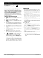
Section 1 Safety Rules
Section 1 Safety Rules
!
Most accidents are the result of negligence and carelessness, usually caused by failure of the operator to follow simple but necessary safety precautions. The
following safety precautions are suggested to help prevent such accidents. The safe operation of any machinery is a big concern to consumers and
manufacturers.Your Stand Up Markers have been designed with many built-in safety features. However, no
one should operate this product before carefully reading
this Operators Manual.
Transporting
1.
2.
3.
General Operation & Repair
1.
2.
3.
4.
5.
6.
7.
8.
9.
NEVER permit anyone near machinery while in operation.
Excessive speed can cause marker damage.
NEVER allow anyone to be near the drill when cycling
the markers.
Reduce speed of the tractor when transporting over uneven or rough terrain. Avoid all chuck holes and washboard areas in roads.
Reduce speed of the tractor when transporting over hills
or steep slopes.
DO NOT lubricate, adjust or repair the drill while it is in
operation.
Use "Slow Moving Vehicle" emblem for warning vehicles
approaching from the rear.
DO NOT permit smoking, sparks, or an open flame
where combustible lubricants or liquids are being used.
!
CAUTION! Escaping fluid under pressure can have sufficient force to penetrate the skin.
Check all hydraulic lines and hoses BEFORE applying
pressure. Fluid escaping from a very small hole can be
almost invisible. Use paper or cardboard, NOT BODY
PARTS, to check for suspected leaks. If injured, seek
medical assistance from a doctor that is familiar with this
type of injury. Foreign fluids in the tissue must be surgically removed within a few hours or gangrene will result.
3/19/03
Great Plains Mfg., Inc.
4.
5.
Use good judgement when transporting tractor and implements on the highway. Always maintain complete control of the machine.
Use warning flags or approved warning lights at night
and during other periods of poor visibility. Do your best
to prevent highway accidents.
When in transport, use accessory lights and devices for
adequate warning to operators of other vehicles and use
safety hitch chain. Comply with all Federal, State and
Local laws when traveling on public roads.
Reduce speed of the tractor when transporting over hills
or steep slopes.
Reduce speed of the tractor when transporting over uneven or rough terrain. Avoid all chuck holes and washboard areas in roads.
Safety Decals
1.
2.
3.
4.
Your Stand Up Markers come equipped with all safety
decals in place. They were designed to help you safely
operate your Markers. Read and follow their directions.
Keep safety decals clean and legible.
Replace all damaged or missing safety decals. To order
new safety decals go to your Great Plains Dealer and
refer to the parts section for safety decal package part
number.
Replace these decals whenever they become worn or unreadable. To instal new safety decals:
a. Clean the area the decal is to be placed
b. Peel backing from the decal. Press firmly on to surface being careful not to cause air bubbles under the
decal.
113-324M
-3
Section 2 Assembly Instructions & Set-Up
Section 2 Assembly Instructions & Set-Up
Torque Values Chart for UNC Threads
Bolt Head Identification
Bolt Size
(Inches)
in-tpi1
Grade 2
Grade 5
Bolt Head Identification
Bolt Size
(Metric)
Grade 8
pitch4
5.8
8.8
10.9
Class 5.8
Class 8.8
Class 10.9
N · m2
ft-lb3
N·m
ft-lb
N·m
ft-lb
mm x
N·m
ft-lb
N·m
ft-lb
N·m
1/4" - 20
7.4
5.6
11
8
16
12
M 5 X 0.8
4
3
6
5
9
7
1/4" - 28
8.5
6
13
10
18
14
M6X1
7
5
11
8
15
11
ft-lb
5/16 - 18
15
11
24
17
33
25
M 8 X 1.25
17
12
26
19
36
27
5/16" - 24
17
13
26
19
37
27
M8X1
18
13
28
21
39
29
3/8" - 16
27
20
42
31
59
44
M10 X 1.5
33
24
52
39
72
53
3/8" - 24
31
22
47
35
67
49
M10 X 0.75
39
29
61
45
85
62
7/16" - 14
43
32
67
49
95
70
M12 X 1.75
58
42
91
67
125
93
7/16" - 20
49
36
75
55
105
78
M12 X 1.5
60
44
95
70
130
97
1/2" - 13
66
49
105
76
145
105
M12 X 1
90
66
105
77
145
105
1/2" - 20
75
55
115
85
165
120
M14 X 2
92
68
145
105
200
150
9/16" - 12
95
70
150
110
210
155
M14 X 1.5
99
73
155
115
215
160
9/16" - 18
105
79
165
120
235
170
M16 X 2
145
105
225
165
315
230
5/8" - 11
130
97
205
150
285
210
M16 X 1.5
155
115
240
180
335
245
5/8" - 18
150
110
230
170
325
240
M18 X 2.5
195
145
310
230
405
300
3/4" - 10
235
170
360
265
510
375
M18 X 1.5
220
165
350
260
485
355
3/4" - 16
260
190
405
295
570
420
M20 X 2.5
280
205
440
325
610
450
7/8" - 9
225
165
585
430
820
605
M20 X 1.5
310
230
650
480
900
665
7/8" - 14
250
185
640
475
905
670
M24 X 3
480
355
760
560
1050
780
1" - 8
340
250
875
645
1230
910
M24 X 2
525
390
830
610
1150
845
1" - 12
370
275
955
705
1350
995
M30 X 3.5
960
705
1510
1120
2100
1550
1-1/8" - 7
480
355
1080
795
1750
1290
M30 X 2
1060
785
1680
1240
2320
1710
1 1/8" - 12
540
395
1210
890
1960
1440
M36 X 3.5
1730
1270
2650
1950
3660
2700
1 1/4" - 7
680
500
1520
1120
2460
1820
M36 X 2
1880
1380
2960
2190
4100
3220
1 1/4" - 12
750
555
1680
1240
2730
2010
1 3/8" - 6
890
655
1990
1470
3230
2380
1
in-tpi = head size in inches-threads per inch
1 3/8" - 12
1010
745
2270
1670
3680
2710
2
N· m = newton-meters
1 1/2" - 6
1180
870
2640
1950
4290
3160
3
ft-lb= foot pounds
1 1/2" - 12
1330
980
2970
2190
4820
3560
2
mm x pitch = millimeters x thread pitch
Pre-Assembly Checklist
Check
All major components
Have a fork lift or loader along with chains and safety
stands ready for the assembly task.
Fasteners that were shipped with the Folding No-Till Drill.
NOTE: Some of the hardware from the factory has been
installed in the location where it will be used.
If you are unsure where a fastener is used, use the parts
section of this manual to identify it. Be sure the part gets
used in the correct location.
Have a minimum of 2 people at hand while assembling the
Stand Up Markers.
4
113-324M
Great Plains Mfg., Inc.
3/19/03
Section 3 Operating Instructions
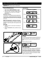
Installation Instructions
Refer to the parts section of this manual for visual
representation of the parts and their locations.
1. Attach fittings to cylinder ports. Attach the needle
valve and hoses to the cylinder fittings as shown in
Fig.???. Route hoses down to the drill frame and
along the back side of the drill frame tubes to the
center of the drill.
Important: Before folding the marker, bleed all the air
out of the hydraulic system. Refer to "Bleeding of the Hydraulics" on page 5.
the marker cylinder pin from the rod end of the cylinder, support the cylinder with the base end pin and
block supporting the body of the cylinder on the first
marker section. Cycle the marker cylinder several
times to work the air out of the system.
3. After all of the air is removed from the system, refer
to Fig.??? and repin the cylinder with the clevis pin
(# ), 1/8" cotter pin (# ), and 1" flat washers (# ).
4. Referring to Fig.???, adjust the speed of the marker
with the needle valve (# ) to a low setting. Fold the
marker up and down a few times and recheck for
pinching and kinking of hoses. Reset folding speed
with the needle valve to a safe speed.
2. To bleed the air out of the hydraulic system, remove
Section 3 Operating Instructions
Bleeding of the Hydraulics
1. Be sure tractor hydraulic reservoir if full.
Note: Never attempt to bleed an O-ring type fitting. Instead, choose a pipe or JIC fitting nearby.
2. With the marker(s) in field position, crack the hydraulic hose fitting(s) located at the base end of the
cylinder(s). With your tractor at an idle speed, activate your tractor hydraulic valve until hydraulic oil
seeps out around the hose ends. Tighten the hose
end fittings and repeat this process with the hose
end fitting(s) located at the rod end of the cylinder(s). If dual markers are used with a sequence
valve, follow the procedure above for one marker
cylinder. Then crack the fittings on the back side of
the sequence valve, activate the tractor hydraulics
valve until hydraulic oil seeps out around the hose
ends. Tighten the hose end fittings and repeat the
complete process for the opposite marker cylinder.
3. Fold and unfold the marker(s) slowly in order to work
all the air out of your marker hydraulics. Use caution
when folding and unfolding the marker for the first
time, and check for pinching and kinking of hoses.
!
CAUTION!
Never allow anyone near the drill when cycling the markers.
4. The marker hydraulic system is equipped with a
needle valve to control how fast the marker operates. Systems without a sequence valve have needle valves at each cylinder. On systems with a
sequence valve, the needle valve is built into the sequence valve body. There are two hex adjustment
heads, one for each side of the drill. To adjust your
markers, screw the needle valve in to adjust the
marker speed to a low setting. Fold the marker up
and down a few times and recheck for pinching and
kinking of hoses. With the tractor engine at an oper-
3/19/03
Great Plains Mfg., Inc.
ating rpm, adjust the needle valve to limit the marker
to a safe operating speed. Excessive folding speeds
can cause marker damage.
!
CAUTION!
Excessive folding speeds can cause marker damage!
!
WARNING!
Escaping Fluid under pressure can have sufficient force to
penetrate the skin. Check all hydraulic lines and houses before applying pressure. Fluid escaping from a very small hole
can be almost invisible. Use paper or cardboard, not body
parts, to check for suspected leaks. If injured, seek medical assistance form a doctor that is familiar with this type of injury.
Foreign fluids in the tissue must be surgically removed within
a few hours or gangrene will result.
General Notes
The markers cycle in the following sequence
(1)
(2)
(3)
(4)
(5)
Right Up, Left Up
Right Down, Left Up
Right Up, Left Up
Right Up, Left Down
Sequence Repeats
Note: JIC fittings do not require high torque. JIC and
O-Ring fittings do not require sealant. Always use liquid
pipe sealant when adding or replacing pipe thread fittings. To avoid possible danger of cracking hydraulic fittings from over tightening, DO NOT use plastic sealant
tape.
Marker Transporting
Always transport the marker with it folded in the flat fold
position. Make sure the second marker section(s) rests
securely on the transport carrier(s).
113-324M
-5
Section 4 Maintenance & Lubrication
Section 4 Maintenance & Lubrication
Lubrication
General Maintenance
1. After using your Stand Up Markers for several
hours, check all bolts to be sure they are tight.
2. Replace any worn, damaged or illegible safety decals by obtaining new decals from your Great
Plains Dealer.
Breakaway Protection
The marker arm is attached to the marker body with a
3/8" shear bolt. If excessive force is put on the marker
during operation, the shear bolt will break, allowing the
marker arm to swing away rather than cause damage to
the marker.
Note: The breakaway bolt is a 3/8"-16 x 1 3/4" long grade 2 (G.P. # 802-253C). It is identified as a grade 2 by
having no marks on the head. If it breaks, it must be replaced by an equivalent grade 2 bolt to prevent marker
damage.
Lubrication Symbols
50
Lubrication is required every 50 hours of operation.
10
Lubrication is required every 10 hours of operation.
As
Required
Use a multipurpose spray lube. Use as required.
Do not over lubricate.
Storage
Seasonally
3. Lubricate all pivots as indicated in the following instructions.
4. Store the 3-Point Drill inside if possible for longer
drill life.
Lubrication is required
25
Hinges
The marker body hinge pivots require greasing every 2025 hours of operation. Each marker has two grease fittings located at the center of each end of the first section.
12669
Type of Lubrication: Grease
2-3 Years
Disk Bearings
12668
The tapered roller bearings in the disk hub are lubricated
at the factory. Under normal conditions, the bearings
need to be repacked every 2 to 3 years. If the grease
seal or grease cap becomes damaged or is missing, the
hub should be disassembled, cleaned and bearings repacked. A new seal or grease cap should be installed.
Type of Lubrication: Grease
6
113-324M
Great Plains Mfg., Inc.
3/19/03
Section 5 Troubleshooting Guide
Section 5 Troubleshooting Guide
Problem
Solution
Hydraulic Marker functioning
improperly
a. Check all hose fittings & connections for air and oil leaks.
b. The chain on the folding marker should be slack when the marker is both
fully extended and fully raised.
c. Check tractor hydraulic oil level.
d. Check all bolts and fasteners.
e. If needle valve is plugged; open valve, cycle markers, and reset the needle valve.
f. Double selector valve positioned for fold cylinders. Shift valve to marker
sequence position.
Blade does not mark
a. The marker folding linkage and chain must have enough slack to allow the
marker disk to drop down into depressions in the field. Maximum down
float should be limited by the slots at the rod end of the marker cylinder,
and not by the chain Read the adjustments section of this manual when
adding slack to the chain.
b. The blade may be reversed to pull dirt in or throw dirt out depending on
soil conditions. See disk adjustments in this manual.
c. An optional smooth blade is available through your Great Plains dealer.
The notched blade comes with your marker as standard equipment.
3/19/03
Great Plains Mfg., Inc.
113-324M
-7
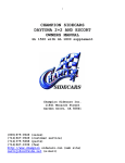
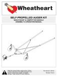
Section 6 Folding Hydraulic Marker {12’, 14’, & 15’ Drills}
10224
8
113-324M
Great Plains Mfg., Inc.
8/19/04
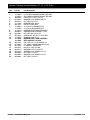
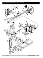
Section 6 Folding Hydraulic Marker {12’, 14’, & 15’ Drills}
Ref.
Part No.
Part Description
1.
113-060H
113-061H
806-006C
804-022C
803-021C
113-110D
802-152C
113-086H
113-085H
113-062H
800-001C
803-036C
801-054C
113-353D
113-563S
113-364S
805-042C
810-005C
811-019C
802-041C
804-017C
804-015C
803-020C
804-006C
803-006C
LH FOLDING MARKER MOUNT WELDMT
RH FOLDING MARKER MOUNT WELDMT
U-BOLT 5/8-11 X 3 17/32 X 5
WASHER LOCK SPRING 5/8 PLT
NUT HEX 5/8-11 PLT
MARKER BODY PIVOT
HHCS 1/4-20X2 GR5
12',14'& 15' LH MARKER EXT.
12',14'& 15' RH MARKER EXT.
MARKER LEVER ARM WELDMENT
GREASE ZERK STRAIGHT 1/4-28
NUT HEX JAM 1/2-13 PLT
SCREW SET SQ HD. 1/2-13X1 GR5
MARKER TUBE 51 LG
MARKER DISC & HUB ASSEMBLY
REPLACED BY 113-563S
PIN LOCK 1/2 X 3 1/2 USABLE LG
CYL 2X8X1.12 ROD SINGLE ACTING
PL 3/8MNPT BREATHER
HHCS 1/2-13X3 1/2 GR5
WASHER FLAT 1/2 USS PLT
WASHER LOCK SPRING 1/2 PLT
NUT HEX 1/2-13 PLT
WASHER LOCK SPRING 1/4 PLT
NUT HEX 1/4-20 PLT
2.
3.
4.
5.
6.
7.
8.
9.
10.
11.
12.
13.
14.
15.
16.
17.
18.
19.
20.
21.
22.
8/19/04
Great Plains Mfg., Inc.
113-324M
9
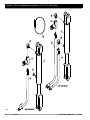
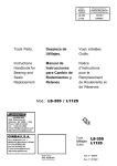
Section 6 Folding Hydraulic Marker {20’, 27’, & 30’ Drills}
10227
10
113-324M
Great Plains Mfg., Inc.
8/19/04
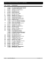
Section 6 Folding Hydraulic Marker {20’, 27’, & 30’ Drills}
Ref.
Part No.
Part Description
1.
113-061H
113-060H
806-006C
804-022C
803-021C
113-110D
802-152C
802-113C
803-015C
804-014C
805-042C
113-063H
800-001C
113-062H
113-111D
113-066H
113-067H
113-148D
113-132D
802-079C
804-011C
804-013C
803-014C
802-045C
804-015C
803-020C
113-083H
113-082H
113-064H
113-065H
802-159C
803-043C
803-036C
801-054C
113-355D
113-354D
804-017C
802-041C
810-005C
811-019C
804-015C
803-020C
804-006C
803-006C
113-563S
113-364S
RH FOLDING MARKER MOUNT WELDMT
LH FOLDING MARKER MOUNT WELDMT
U-BOLT 5/8-11 X 3 17/32 X 5
WASHER LOCK SPRING 5/8 PLT
NUT HEX 5/8-11 PLT
MARKER BODY PIVOT
HHCS 1/4-20X2 GR5
HHCS 7/16-14X1 3/4 GR5
NUT HEX 7/16-14 PLT
WASHER LOCK 7/16 PLT
PIN LOCK 1/2 X 3 1/2 USABLE LG
MARKER ARM WELDMENT
GREASE ZERK STRAIGHT 1/4-28
MARKER LEVER ARM WELDMENT
HINGE PIVOT BAR
LH EXT PIVOT BRACKET WELDMENT
RH EXT PIVOT BRACKET WELDMENT
CHAIN 1/4 X 67 INCHES
CHAIN 1/4X94 INCHES PROOF PLT
HHCS 3/8-16X1 1/4 GR5
WASHER FLAT 3/8 USS PLT
WASHER LOCK SPRING 3/8 PLT
NUT HEX 3/8-16 PLT
HHCS 1/2-13X5 GR5
WASHER LOCK SPRING 1/2 PLT
NUT HEX 1/2-13 PLT
20' LH MARKER EXTENSION
20' RH MARKER EXTENSION
RH MARKER EXTENSION WELDMENT
LH MARKER EXTENSION WELDMENT
HHCS 5/16-18X1 GR5
NUT HEX WHIZ 5/16-18 PLT
NUT HEX JAM 1/2-13 PLT
SCREW SET SQ HD. 1/2-13X1 GR5
MARKER TUBE 57 LONG
13' MARKER TUBE 46 1/2 LONG
WASHER FLAT 1/2 USS PLT
HHCS 1/2-13X3 1/2 GR5
CYL 2X8X1.12 ROD SINGLE ACTING
PL 3/8MNPT BREATHER
WASHER LOCK SPRING 1/2 PLT
NUT HEX 1/2-13 PLT
WASHER LOCK SPRING 1/4 PLT
NUT HEX 1/4-20 PLT
MARKER DISC & HUB ASSEMBLY
REPLACED BY 113-563S
2.
3.
4.
5.
6.
7.
8.
9.
10.
11.
12.
13.
14.
15.
16.
17.
18.
19.
20.
21.
22.
23.
24.
25.
26.
27.
28.
29.
30.
31.
32.
33.
34.
35.
36.
37.
38.
8/19/04
Great Plains Mfg., Inc.
113-324M
11
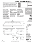
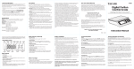
Section 6 Marker Disk Assembly
11244
12
113-324M
Great Plains Mfg., Inc.
8/19/04
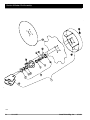
Section 6 Marker Disk Assembly
Ref.
Part No.
Part Description
1.
113-563S
113-564S
113-372S
113-562H
816-014C
822-030C
822-080C
890-614C
815-001C
804-025C
803-053C
805-019C
820-094C
820-098C
113-369H
802-125C
803-159C
MARKER DISC & HUB ASSEMBLY
REP BY 113-563S
REP BY 113-564S
1 SPINDLE MARKER WELDMENT
TINE GAUGE WHEEL HUB SEAL
BEARING CONE L44643
BEARING CUP L44610
GREASE CAP #1505
TINE GW HUB
WASHER FLAT 3/4 SAE PLT
NUT HEX SLOTTED 3/4-16
PIN COTTER 5/32 X 1 PLT
16 4-BOLT NOTCHED MARKER DISK
14 4-BOLT MARKER DISK
DEPTH BAND 10 4-BOLT 4B.C.
LUG BOLT
NUT LUG 1/2-20 X 60 DEG PLT
2.
3.
4.
5.
6.
7.
8.
9.
10.
11.
12.
13.
14.
8/19/04
Great Plains Mfg., Inc.
113-324M
13
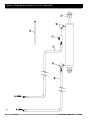
Section 7 Single Marker Hydraulics {15’ & 20’ 3-Point Drills}
11383
14
113-324M
Great Plains Mfg., Inc.
8/19/04
Section 7 Single Marker Hydraulics {15’ & 20’ 3-Point Drills}
Ref.
Part No.
Part Description
1.
2.
3.
4.
5.
810-005C
811-156C
811-026C
810-058C
811-015C
811-017C
811-297C
811-300C
800-082C
Hydraulic Cylinder 2" x 8" Stroke
Elbow 3/8" MNPT
Elbow 3/8" MNPT x 3/8" FNPT
Needle Valve 3/8"
Hydraulic Hose 1/4" x 192" Long - 20’ Drill
Hydraulic Hose 1/4" x 156" Long - 15’ Drill
Hydraulic Hose 1/4" x 212" Long - 20’ Drill
Hydraulic Hose 1/4" x 176" Long - 15’ Drill
Cable Tie 21" Long
6.
7.
8/19/04
Great Plains Mfg., Inc.
113-324M
15
Section 7 Dual & Single Marker Hydraulic {27’ & 30’ 3-Point Drills}
10058
16
113-324M
Great Plains Mfg., Inc.
8/19/04
Section 7 Dual & Single Marker Hydraulic {27’ & 30’ 3-Point Drills}
Ref.
Part No.
Part Description
1.
2.
3.
4.
5.
810-005C
811-281C
811-026C
810-058C
811-129C
811-058C
811-294C
811-299C
800-082C
Hydraulic Cylinder 2" x 8" Stoke
Elbow 3/8" MNPT
Elbow 3/8" MNPT x 3/8" MNPT
Needle Valve 3/8"
Hydraulic Hose 1/4" x 234" Long 27’ Drill
Hydraulic Hose 1/4" x 303" Long 30’ Drill
Hydraulic Hose 1/4" x 254" Long 27’ Drill
Hydraulic Hose 1/4" x 323" Long 30’ Drill
Cable Tie 21" Long
6.
7.
8/19/04
Great Plains Mfg., Inc.
113-324M
17
Section 7 Dual Marker Hydraulics Used With CDH, CPH, & CC
10258
18
113-324M
Great Plains Mfg., Inc.
8/19/04
Section 7 Dual Marker Hydraulics Used With CDH, CPH, & CC
Ref.
Part No.
Part Description
1.
2.
3.
4.
5.
6.
7.
8.
9.
10.
11.
113-263D
802-023C
804-013C
803-014C
810-006C
811-021C
806-002C
804-015C
803-020C
811-009C
811-017C
811-015C
811-214C
810-005C
811-156C
810-058C
3-Point Sequence Valve Mount
Bolt, Hex 3/8"-16 x 1 3/4" Long
Washer, Lock 3/8"
Nut, Hex 3/8"-16
Sequence Valve
Hydraulic Fitting 1/2" FNPT Swivel x 3/4" MORB
U-Bolt 1/4"-13 x 3 1/2" x 4 1/2" Long
Washer, Lock 1/2"
Nut, Hex 1/2"-13
Hydraulic Fitting 1/2" FNPT Tee
Hydraulic Hose 1/4" x 156" Long {15’ Drill}
Hydraulic Hose 1/4" x 192" Long {20’ Drill}
Hydraulic Fitting 1/2" MNPT x 3/8" FNPT Street L
Hydraulic Cylinder 2" x 8" Stroke
Hydraulic Fitting Elbow 3/8" MNPT
Needle Valve 3/8"
113-137A
3-Point Drill Marker Valve Kit for use with Combination Drill Hitch, Center Pivot Hitch and
Coulter Caddy. Includes 1 Each of Items 1, 5, 7 & 10; 2 Each of Items 2 Through 4, 8 & 9;
and 3 Each of Item 6.
12.
13.
14.
15.
Note: To avoid cracking the hydraulic fittings, DO NOT use plastic sealant tape. Use only liquid pipe sealant to seal
the hydraulic fittings.
8/19/04
Great Plains Mfg., Inc.
113-324M
19
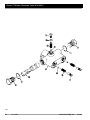
Section 7 Selector Sequence Valve {810-006C}
10037
20
113-324M
Great Plains Mfg., Inc.
8/19/04
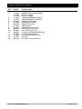
Section 7 Selector Sequence Valve {810-006C}
Ref.
Part No.
Part Description
1.
2.
3.
4.
5.
6.
7.
8.
9.
1V1880
1V1882
1V2003
1V2003
3-V4153-022
2A0017-6
2A0017-8
2A9018-3
2A9024-1
2A0353-12
O-Ring Boss Plug Assembly
Spool
Body Machining
Check Valve Retainer
O-Ring Boss Plug Assembly
3/16" Ball
1/4" Ball
Check Valve Spring
Spring
Shipping Plug
3/19/03
Great Plains Mfg., Inc.
113-324M
21