Download FireProof User Guide Version 2.20
Transcript
FP manual server.qxd 6/11/01 3:33 PM Page 1 FireProof Application Switch and Fast Ethernet Platforms Software Version: 2.20 FP manual server.qxd 6/11/01 3:24 PM Page 2 FP manual server.qxd 6/11/01 3:24 PM Page I IMPORTANT NOTICE This guide is delivered subject to the following conditions and restrictions: Copyright Radware Ltd. 2000. All rights reserved. The copyright and all other intellectual property rights and trade secrets included in this guide are owned by Radware Ltd. The guide is provided to Radware customers for the sole purpose of obtaining information with respect to the installation and use of the FireProof, and may not be used for any other purpose. The information contained in this guide is proprietary to Radware and must be kept in strict confidence. It is strictly forbidden to copy, duplicate, reproduce or disclose this guide or any part thereof without the prior written consent of Radware. FireProof User Guide I FP manual server.qxd 6/11/01 3:24 PM Page II FP manual server.qxd 6/11/01 3:24 PM Page III SAFETY INSTRUCTIONS CAUTION Due to the risks of electrical shock, and energy, mechanical, and fire hazards, any procedures that involve opening panels or changing components must be performed by qualified service personnel only. To reduce the risk of fire and electrical shock, disconnect the instrument from the power line before removing cover or panels. SERVICING Do not perform any servicing other than that contained in the operating instructions unless you are qualified to do so. There are no user-serviceable parts inside the unit chassis. HIGH VOLTAGE Any adjustment, maintenance, and repair of the opened instrument under voltage should be avoided as much as possible and, when inevitable, should be carried out only by a skilled person who is aware of the hazard involved. Capacitors inside the instrument may still be charged even if the instrument has been disconnected from its source of supply. GROUNDING Before connecting this instrument to the power line, the protective earth terminals of this instrument must be connected to the protective conductor of the (mains) power cord. The mains plug shall only be inserted in a socket outlet provided with a protective earth contact. The protective action must not be negated by use of an extension cord (power cable) without a protective conductor (grounding). FireProof User Guide III FP manual server.qxd 6/11/01 3:24 PM Page IV Safety Instructions FUSES Make sure that only fuses with the required rated current and of the specified type are used for replacement. The use of repaired fuses and the short-circuiting of fuse holders must be avoided. Whenever it is likely that the protection offered by fuses has been impaired, the instrument must be made inoperative and be secured against any unintended operation. LINE VOLTAGE Before connecting this instrument to the power line, make sure the voltage of the power source matches the requirements of the instrument. WARRANTY This Radware Ltd. product is warranted against defects in material and workmanship as follows: z Hardware - for a period of 15 months from date of shipment. z Software - for a period of 12 months from date of software registration. During the warranty period, Radware will, at its option, either repair or replace products which prove to be defective. For warranty service or repair, this product must be returned to a service facility designated by Radware. Buyer shall prepay shipping charges, duties, and taxes for products returned to Radware and Radware shall pay shipping charges to return the product to Buyer. Radware warrants that its firmware designed by Radware for use with an instrument will execute its programming instructions when properly installed on that instrument. Radware does not warrant that the operation of the instrument or firmware will be uninterrupted or error-free. LIMITATION OF WARRANTY The foregoing warranty shall not apply to defects resulting from improper or inadequate maintenance by Buyer, Buyer-supplied firmware or interfacing, unauthorized modification or misuse, operation outside of the environmental specifications for the product, or improper site preparation or maintenance. No other warranty is expressed or implied. Radware specifically disclaims the implied warranties of merchantability and fitness for a particular purpose. IV FireProof User Guide FP manual server.qxd 6/11/01 3:24 PM Page V Safety Instructions EXCLUSIVE REMEDIES The remedies provided herein are Buyer's sole and exclusive remedies. Radware shall not be liable for any direct, indirect, special, incidental, or consequential damages, whether based on contract, tort, or any legal theory. TRADEMARKS FireProof, MultiVu and Configware are trade names of Radware Ltd. This document contains trademarks registered by their respective companies. SPECIFICATION CHANGES Specifications are subject to change without notice. NOTE: This equipment has been tested and found to comply with the limits for a Class A digital device pursuant to Part 15 of the FCC Rules and EN55022 Class A, EN 50082-1 For CE MARK Compliance. These limits are designed to provide reasonable protection against harmful interference when the equipment is operated in a commercial environment. This equipment generates, uses and can radiate radio frequency energy and, if not installed and used in accordance with the instruction manual, may cause harmful interference to radio communications. Operation of this equipment in a residential area is likely to cause harmful interference in which case the user will be required to correct the interference at his own expense. FireProof/DC If you purchased one of these devices, make note of the following additional instructions. RESTRICT AREA ACCESS This device should only be installed in a restricted access area. INSTALLATION CODES This device must be installed in accordance with the National Electrical Code, Articles 110-16, 110-17, and 110-18 and the Canadian Electrical Code, Section 12. FireProof User Guide V FP manual server.qxd 6/11/01 3:25 PM Page VI Safety Instructions OVERCURRENT PROTECTION A readily accessible listed branch-circuit over current protective device 15 A must be incorporated in the building wiring. - To Reduce the Risk of Electrical Shock and Fire ) Caution 1. All servicing should be undertaken only by qualified service personnel. There are not user serviceable parts inside the unit. 2. DO NOT plug in, turn on or attempt to operate an obviously damaged unit. 3. Ensure that the chassis ventilation openings in the unit are NOT BLOCKED. 4. Replace a blown fuse ONLY with the same type and rating as is marked on the safety label adjacent to the power inlet, housing the fuse. 5. DO NOT operate the unit in a location where the maximum ambient temperature exceeds 40 degrees C. 6. Be sure to unplug the power supply cord from the wall socket BEFORE attempting to remove and/or check the main power fuse. Pour Reduire Les Risques d'Electrocution et d'Incendie ) Attention: 1. Toutes les opérations d'entretien seront effectuées UNIQUEMENT 2. 3. 4. 5. 6. VI par du personnel d'entretien qualifié. Aucun composant ne peut être entretenu ou remplacé par l'utilisateur. NE PAS connecter, mettre sous tension ou essayer d'utiliser un ensemble qui est défectueux de manière évidente. Assurez vous que les ouvertures de ventilation du châssis NE SONT PAS OBSTRUEES. Remplacez un fusible qui a sauté, SEULEMENT par un fusible du même type et de même capacité, comme indiqué sur l'étiquette de sécurité proche de l'entrée de l'alimentation qui contient le fusible. NE PAS UTILISER l'équipement dans des locaux dont la température maximale dépasse 40°C. Assurez vous que le cordon d'alimentation a été déconnecté AVANT d'essayer de l'enlever et / ou vérifier le fusible de l'alimentation générale. FireProof User Guide FP manual server.qxd 6/11/01 3:25 PM Page VII Safety Instructions βnahmen zum Schutz vor elektrischem Schock und Feuer ) Ma 1. Alle Wartungsarbeiten sollten ausschlieβlich von geschultem 2. 3. 4. 5. 6. Wartungspersonal durchgefuhrt werden. Keine im Gerät befindlichen Teile durfen vom Benutzer gewartet werden. Offensichtlich defekte oder beschädigte Geräte durfen nicht angeschlossen, eingeschaltet oder in Betrieb genommen werden. Stellen Sie sicher, dass die Beluftungsschlitze am Gerät nicht blockiert sind. Ersetzen Sie eine defekte Sicherung ausschlieβlich mit Sicherungen laut Sicherheitsbeschriftung. Betreiben Sie das Gerät nicht in Räumen mit Temperaturen uber 40°C. Trennen Sie das Netzkabel von der Steckdose bevor Sie die Hauptsicherung prufen oder austauschen. FireProof User Guide VII FP manual server.qxd 6/11/01 3:25 PM Page VIII FP manual server.qxd 6/11/01 3:25 PM Page IX ABOUT THIS GUIDE Chapter 1\ Introducing FireProof This chapter introduces Radware's FireProof product. FireProof is a dynamic load balancing system for effective management of traffic. Chapter 2 \ Installing FireProof This chapter describes FireProof setup and Configware management software installation. Chapter 3 \ Configuring FireProof This chapter describes how to configure FireProof to your requirements, using the Configware management software. Chapter 4 \ Monitoring FireProof Performance This chapter describes how to view detailed performance graphs, which help monitor FireProof performance. Appendix A \ Example Configurations This Appendix provides examples of FireProof configurations. Appendix B \Troubleshooting This Appendix provides troubleshooting solutions to some common FireProof problems. Appendix C \ ASCII Command Line Interface This Appendix defines the CLI for FireProof. APPENDIX D \ Software License Upgrade This appendix provides the procedures required to upgrade your software, using either Configware or ASCII CLI. FireProof User Guide IX FP manual server.qxd 6/11/01 3:25 PM Page X About This Guide Glossary This glossary provides explanations of terms and concepts used in network configurations. X FireProof User Guide FP manual server.qxd 6/11/01 3:25 PM Page XI FP manual server.qxd 6/11/01 3:25 PM Page XII CONTENTS Chapter 1 - Introducing FireProof (FP) The Problem The Solution FireProof Network Design FireProof Entry Level Product Chapter 2 - Installing FireProof Checking the Contents Mounting the Device Connecting FireProof to Your Network AC Power Connection ASCII Terminal (Serial) Connection LAN Connections Configuring FireProof IP Host Parameters FireProof Specifications and Requirements Hardware (Fast Ethernet Platform) Hardware (Application Switch Platform) LAN Interfaces (Fast Ethernet Platform) LAN Interfaces (Application Switch Platform) Hardware Requirements Software Requirements Installing Configware Management Software FireProof User Guide 1-1 1-2 1-2 1-3 1-3 2-1 2-2 2-2 2-3 2-3 2-3 2-4 2-5 2-9 2-9 2-9 2-9 2-10 2-10 2-10 2-11 XII FP manual server.qxd 6/11/01 3:25 PM Page XIII Contents Chapter 3 - Configuring FireProof Getting Started Running Configware Using Buttons Permanently Adding Devices to Configware Connecting to a Device Zoom View Viewing Traps Setting Up a VLAN Creating VLANs Configuring VLAN Parameters Setting Interface Addresses and IP Router Options Setting Up Firewalls Configuring Firewalls Creating Virtual IP Addresses Mapping NAT Addresses to Virtual IP Addresses Smart NAT Creating Rules for Port Connection Configuring Application Aging Configuring Firewall Grouping Full Path Health Monitoring Controlling Traffic to Newly Booted Firewalls Viewing Active Clients Global Configuration Setting Up Redundant FireProof Devices Configuring IP Router Redundancy Configuring Mirroring Configuring a Remote Virtual IP Address Defining Load Balancing Algorithms Configuring Router Settings Adjusting Operating Parameters Configuring Interface Parameters RIP Protocol Parameters RIP Interface Parameters OSPF Protocol Parameters OSPF Interface Parameters OSPF Area Parameters OSPF Link State Database XIII 3-1 3-2 3-2 3-3 3-3 3-7 3-8 3-8 3-12 3-13 3-14 3-16 3-19 3-20 3-22 3-24 3-25 3-31 3-32 3-34 3-38 3-39 3-40 3-41 3-46 3-47 3-49 3-51 3-52 3-55 3-56 3-57 3-58 3-60 3-61 3-63 3-65 3-66 FP manual server.qxd 6/11/01 3:25 PM Page XIV Contents OSPF Neighbor Table Configuring the Router ARP Addresses Setting Up Security Configuring Management Station Access Setting Physical Port SNMP Restrictions Configuring Bridge Settings Bridge Operating Parameters Bridge Forwarding Nodes Configuring Services Configuring Polling Changing Community Names Syslog Reporting Event Log Getting Device Information Viewing Interface Parameters Resetting the Device Setting Device Global Parameters Device Tuning Configuring Via File Setting Up Application Security Configuring Bandwidth Management (BWM) Viewing Active Policies Modifying Policies Modifying Services Viewing and Modifying Differentiated Services Updating Software Chapter 4 - Monitoring FireProof Performance Element Statistics IP Interface Statistics Firewall Statistics Policy Statistics Port Statistics 3-67 3-68 3-69 3-72 3-72 3-73 3-75 3-75 3-76 3-78 3-78 3-79 3-79 3-80 3-81 3-82 3-83 3-84 3-86 3-89 3-92 3-96 3-99 3-100 3-105 3-110 3-113 4-1 4-2 4-9 4-11 4-13 4-15 XIV FP manual server.qxd 6/11/01 3:25 PM Page XV Contents Appendix A - Example Configurations Example Example Example Example Example Example Example Example Example Example XV 1: Simple FireProof Configuration 3: One Leg (Lollipop) Configuration 4: Typical FireProof Configuration 5: Redundant FireProof Configuration 6: Redundant FireProof Configuration Using VLAN 7: DMZ Support with Port Connectivity Rules 8: Application Grouping with FireProof 9: QoS used for Access Control 10: Bandwidth Management 11: Application Security A-1 A-2 A-6 A-8 A-11 A-14 A-17 A-19 A-21 A-25 A-29 Appendix B - Troubleshooting B-1 Appendix C - ASCII Command Line Interface C-1 Appendix D - Software License Upgrade D-1 Glossary G-1 Index I-1 FP manual server.qxd 6/11/01 3:25 PM Page 1-1 M Introducing FireProof (FP) FireProof is a dynamic load balancing system for effective management of traffic on multiple firewalls and other VPN and transparent devices. Based on technologies of the award-winning Radware Web Server Director™ family of IP traffic managers, FireProof greatly improves firewall performance while maximizing uptime. An ideal solution for large organizations that require top firewall performance, Radware's FireProof system offers powerful load balancing and fault tolerance capabilities, which together ensure the highest degree of availability and an effective growth path. This chapter contains the following information: z The Problem, page 1-2. z The Solution, page 1-2. z FireProof Network Design, page 1-3. z FireProof Entry Level Product, page 1-3. FireProof User Guide 1-1 FP manual server.qxd 6/11/01 3:25 PM Page 1-2 Chapter 1 - Introducing FireProof The Problem Generally, firewalls have a limited traffic load capacity. To accommodate traffic growth, organizations can either install the existing firewall on a more powerful machine or add more firewall devices. However, these solutions can prove to be problematic. Installing a firewall on a more powerful machine is costly and does not fully solve capacity related problems, since the new firewall will eventually reach its maximum growth potential. Additionally, a single firewall is a single point of failure, causing an interruption in service when the firewall is busy or down. Organizations encounter numerous problems when installing multiple firewalls. First, different client groups must be configured, which is a time-consuming procedure. Furthermore, multiple points of failure are created with the addition of each firewall. Since the traffic load is not dynamically shared between units, the firewalls are not used optimally. Finally, to achieve fault tolerance and redundancy between firewalls, hot standby, or idle, units must be deployed on the network. The Solution Radware's FireProof system answers the challenges of firewall performance and availability by providing load balancing and fault tolerance between all firewall units. In addition Radware has designed the SynApps Architecture1 which provides the following solutions: z z z z Health monitoring Traffic re-direction Bandwidth management Application security Using this architecture, FireProof maximizes your site's performance, providing a high level of service at all times. 1 1-2 The SynApps architecture is only available in the Application Switch platform. FireProof User Guide FP manual server.qxd 6/11/01 3:25 PM Page 1-3 Chapter 1 - Introducing FireProof The following diagram represents a typical FireProof configuration: Firewalls Local Clients FireProof FireProof Access Router FireProof Network Design FireProof is designed to load balance IP traffic between a set of firewall machines. The firewalls may be from different vendors. To ensure data flow consistency the security rules should be identical. z All traffic must physically travel through the FireProof unit. This includes traffic to and from the firewalls. If configured in routing mode, the administrator must ensure that the IP address of FireProof is the default gateway of all load balanced IP packets traveling to and from the firewalls. z FireProof keeps track of the packets traveling from the local network to the Internet, and from the Internet to the local network. FireProof Entry Level Product Radware introduces the FireProof Entry Level product. This is a basic model of the FireProof. It supports all functionalities of the FireProof family and only differs with regard to its limitations. FireProof User Guide 1-3 FP manual server.qxd 6/11/01 3:25 PM Page 1-4 FP manual server.qxd 6/11/01 3:25 PM Page 2-1 N Installing FireProof This chapter describes how to setup FireProof and install Configware, Radware's management software. If you prefer to use ASCII CLI, refer to Appendix C for a full list of commands. This chapter is divided into the following sections: z Checking the Contents, page 2-2. z Mounting the Device, page 2-2. z Connecting FireProof to Your Network, page 2-3. z Configuring FireProof IP Host Parameters, page 2-5. z FireProof Specifications and Requirements, page 2-9. z Installing Configware Management Software, page 2-11. FireProof User Guide 2-1 FP manual server.qxd 6/11/01 3:25 PM Page 2-2 Chapter 2 - Installing FireProof Checking the Contents Before beginning the hardware installation, open the box and check that the following components are included: z FireProof device z Configware Management Software CD Rom z User's Manual z One power cable (Only for countries using 110v power supply) z One serial cable z Two cross cables (Application Switch platform only) z A set of mounting brackets If you are missing any of the above components, please contact your FireProof reseller. Mounting the Device FireProof can be either racked-mounted or mounted on a tabletop. The package includes brackets to enable rack-mounting of the device. Rubber feet are attached to the bottom of the device to enable tabletop mounting. Note: After mounting, ensure that there is adequate airflow surrounding the device. ) To rack-mount the device: 1. 2. 2-2 Attach one bracket to each side of the device, using the screws provided. Attach the device to the rack with the mounting screws. FireProof User Guide FP manual server.qxd 6/11/01 3:25 PM Page 2-3 Chapter 2 - Installing FireProof Connecting FireProof to Your Network After you have mounted the device, you must connect the cables to your device. The following connections should be completed, in this order: z AC Power Connection z ASCII Terminal (Serial) Connection z LAN Connections z Configuring the IP Host Parameters AC Power Connection The device should be supplied with AC power via a 1.5m (or 5 foot) standard power cable. ) To connect the AC power connection: 1. 2. Connect the power cable to the main socket, located on the rear panel of the device. Connect the power cable to the grounded AC outlet. ASCII Terminal (Serial) Connection The serial port connector varies depending on the platform of your device, as follows: Fast Ethernet: Application Switch: The serial port connector is a 9-pin connector, which is connected to the rear panel. The serial port connector is a 9-pin connector, which is connected to the front panel. ) To make the ASCII terminal connection: 1. 2. 3. 4. Connect the serial port connector to the front panel. Connect the other end of the serial port connector cable to your computer. Access HyperTerminal. From the HyperTerminal opening window, select the File menu, then Properties, FireProof User Guide 2-3 FP manual server.qxd 6/11/01 3:25 PM Page 2-4 Chapter 2 - Installing FireProof 5. 6. Or Click the Properties icon in the toolbar. The New Connection Properties dialog box is displayed. Click Configure. The Properties dialog box containing the Port Settings tab is displayed. Verify that the fields are set as follows: Bits per second: 19200 Data bits: 8 Parity: None Stop bits: 1 Flow Control: None Note: When using Microsoft's HyperTerminal program, Flow Control should be set to none. 7. Turn on the power to the unit. If the device is connected and operating properly, the PWR and System OK indicators on the front panel are lit continuously. LAN Connections Use a standard UTP or STP cable to connect FireProof to the LANs. The cables used differs in each platform of the device, as follows: Fast Ethernet: Application Switch: In all the ports, a 10/100BaseT cable can be used. In eight of the ports, a 10/100BaseT cable can be used, and in two ports, a 1000BaseSX cable must be used. ) To connect a FireProof port to a network LAN: 1. 2. 2-4 Connect a standard UTP or STP cable to the port interface, located on the front panel. Connect the other end of the cable to the LAN switch. FireProof User Guide FP manual server.qxd 6/11/01 3:25 PM Page 2-5 Chapter 2 - Installing FireProof Configuring FireProof IP Host Parameters FireProof IP host parameters enable an SNMP Network Management Station (NMS) to establish communication with the device. The manual configuration of the device differs depending on the platform, therefore this procedure is divided into two parts. The first procedure, see below, is applicable to the Application Switch platform, and the second procedure, see page 2-8, is applicable to the Fast Ethernet platform. Note: All other FireProof parameters are configured using Radware's Configware software. ) To manually configure FireProof IP host parameters in the 1. 2. 3. Application Switch platform: Ensure that the ASCII terminal is connected to the device. Turn on the power to the device. If you require to access the command line, press any key within three seconds of the boot up. The following command line is displayed: ? @ e w q u r print this list boot (load and go) print fatal exception download via xmodem erase configuration from flash download to secondary boot via xmodem clear Log file If you do not require to access this command line, the Startup Configuration window is automatically displayed. 4. Select the @ symbol to access the Startup Configuration window. The window is displayed, as shown next page. FireProof User Guide 2-5 FP manual server.qxd 6/11/01 3:25 PM Page 2-6 Chapter 2 - Installing FireProof Startup Configuration 0. Exit 1. IP address 2. IP subnet mask 3. Port number 4. Default router IP address 5. RIP version 6. OSPF enable 7. OSPF area ID 8. NMS IP address 9. Community name 10. Configuration file name Enter your choice: 5. Enter the number of the parameter for which you require to define the information. 6. Enter the parameters configuration and click Enter. The value of the parameter is displayed in the screen. The following list defines the parameters in the Startup Configuration window: IP address: The IP address of the interface is the only mandatory parameter. This address is used for SNMP management. IP subnet mask: The IP subnet mask address of the device. The default value of this parameter is the mask of the IP address class. Port number: The port number to which the IP interface is defined. The default value is 1. Other possible values include 1, 2, or 1, 2, 3, 4, or 1, 2, 3, 4, 5, 6, 7, 8, 9, 10, or 100001. If you enter 100001, all the ports are included in the IP VLAN, and the IP interface therefore sits on the IP VLAN. Default router IP address: The IP Address of the router through which the NMS can be reached. The default value for this parameter is: disable the default router IP address. 2-6 FireProof User Guide FP manual server.qxd 6/11/01 3:25 PM Page 2-7 Chapter 2 - Installing FireProof RIP version: The RIP version used by the network router. The default value for this parameter is: disable. OSPF enable: This parameter enables or disables the OSPF protocol. The default value is: disable. OSPF area ID: When the OSPF protocol is enabled, you can enter an area ID other than the default value. Enter an ID in the form of an IP address. The default value is 0.0.0.0. The three remaining parameters are only necessary when the NMS is remote to the device. They offer three different ways to connect to the remote NMS. If the NMS is remote, enter a value for at least one of the three options. NMS IP address: The required NMS IP address. Enter a value if you require to limit the device to a single, specified NMS. The default value is 0.0.0.0 (any NMS). Community name: The community name of the device. The default community name is public. Enter a different name that you want as the community name. Configuration file name: The name of the file, in a format required by the server, which contains the configuration. Select this parameter when you require to download a configure file an NMS. The must, however, be located on the NMS, and the NMS must be located on a TFTP server. When you exit the Startup Configuration window, the device loads that configuration file from the NMS, resets and starts operating with the new configuration. The default value is: no name. Note: FireProof enters a default value for the parameters that are incomplete, with the exception of the IP Address, which is mandatory. A validity check of all the parameters is then performed. FireProof User Guide 2-7 FP manual server.qxd 6/11/01 3:25 PM Page 2-8 Chapter 2 - Installing FireProof ) To manually configure the IP host parameters of the device in the 1. 2. Fast Ethernet platform: Ensure that the ASCII terminal is connected to the device. Turn on the power to the device. The terminal displays the Startup Menu window, as shown below, within three seconds. Startup Menu 1. Download sw 2. Erase config 3. Erase nvram 3. 4. 5. 2-8 Select one of the three options to either download software, erase the existing configuration or to erase nvram. If you do not select or require any of these options, the boot sequence continues. The device detects whether or not it has the necessary configuration, and if not, the Startup Configuration window is displayed. Enter the number of the parameter for which you require to define the information. Enter the parameters configuration and click Enter. The value of the parameter is displayed in the screen. FireProof User Guide FP manual server.qxd 6/11/01 3:25 PM Page 2-9 Chapter 2 - Installing FireProof FireProof Specifications and Requirements Hardware (Fast Ethernet Platform) CPU Microprocessor Ethernet Controller ASCII Terminal Port Memory Intel 960i HD. Intel 82557 Ethernet co-processor. 9-pin female RS-232 connector, DCE Setup: 19200 bps, 8 bits, one stop bit, no parity. 4 MB Flash, 8-32 MB DRAM, 8 MB buffer, 8 KB NVRAM. Hardware (Application Switch Platform) CPU Power PC Switch Architecture ASCII Terminal Port Memory Power PC 750. Galileo GalNet II. 9-pin female RS-232 connector, DCE Setup: 19200 bps, 8 bits, one stop bit, no parity. 8 MB Flash, 64-128 MB SDRAM, 32 KB NVRAM. LAN Interfaces (Fast Ethernet Platform) FireProof comes with two/four priority RJ45 ports for IEEE 802.3 10/100 BaseT. The two/four ports are auto-sensing but can be defined to a specific speed using Configware. FireProof supports half and full-duplex communication on 100 Mbps. FireProof User Guide 2-9 FP manual server.qxd 6/11/01 3:25 PM Page 2-10 Chapter 2 - Installing FireProof LAN Interfaces (Application Switch Platform) FireProof comes with two Gigabit and/or eight Fast Ethernet ports for IEEE 802.3 10/100 BaseT and 1000 BaseSX. All the ports are autosensing. FireProof also supports half and full-duplex communication on 1000 Mbps. Hardware Requirements In order to use the Configware program successfully, your system components must include the following: z Any Java enabled platform running on at least a 200MHz processor z At least 32 Mbytes RAM z 15 Mbytes free disk space z CD-ROM for installation z VGA or SuperVGA color adapter and monitor, 64K colors recommended Software Requirements Java Support (Microsoft Internet Explorer 4.0 or Sun JRE). If you do not have Java support, you can download Microsoft's Java Virtual Machine from their Web site: http://www.microsoft.com/java/vm/dl_vm32.htm. 2-10 FireProof User Guide FP manual server.qxd 6/11/01 3:25 PM Page 2-11 Chapter 2 - Installing FireProof Installing Configware Management Software The Configware Management Software can be installed as a stand-alone application or as a web-based management applet. Refer to Appendix D for installation details on web-based management software. ) To install Configware as a stand-alone application: 1. Insert the Configware CD in the CD Rom drive. The following window is displayed automatically. The following options are displayed on the left side of the screen: z Install Configware: Displays the Configware Web-Based Management installation window in your browser. Refer to Appendix D for further details. z Browse CD: Displays your Windows Explorer enabling you to browse the contents of the CD. This enables you install Configware as a stand-alone application. z Website: Accesses the Radware website in your browser. z View Manual: Displays the manual in Acrobat. FireProof User Guide 2-11 FP manual server.qxd 6/11/01 3:25 PM Page 2-12 Chapter 2 - Installing FireProof Install Java: Enables you to install Java in a quick and easy-to-use set up. z Exit: Closes the window. Select Browse CD. In Windows Explorer, browse to the CD and select the Configware folder. Double-click on the jview_setup.bat file. The Configware 1.40 Installation window is displayed, as shown below. z 2. 3. 4. 2-12 Read the SHRINK-WRAP LICENSE AGREEMENT. In order to continue with set up, you must accept the license agreement by checking the Accept checkbox. This enables the OK button. FireProof User Guide FP manual server.qxd 6/11/01 3:25 PM Page 2-13 Chapter 2 - Installing FireProof 5. Click OK. The Select Install Folder Name window is displayed, as shown below. This window enables you to install the Configware management software in a specified location. Using the Select drive dropdown box and the path dropdown box, you can navigate to the folder in which you require to install Configware. FireProof User Guide 2-13 FP manual server.qxd 6/11/01 3:25 PM Page 2-14 Chapter 2 - Installing FireProof 6. Click Select. The Select your browser path window is displayed, as shown below. 7. Navigate to your browser, usually located in your Program Files folder, and select the .exe file for your browser. Click Open. The Configware files are extracted to your selected destination folder. When the installation is complete a success message dialog box is displayed. Click OK. The installation is complete. 8. 9. Notes: Configware software takes up approximately 15MB of disk space. You can access Configware management software from the Start menu, or via a shortcut on your desktop, or from the configure.bat file located in the Configware folder containing the software. 2-14 FireProof User Guide FPchapter 3.qxd 6/11/01 3:28 PM Page 3-1 O Configuring FireProof Configware is an SNMP-based network management system. It gives you access to a myriad of configuration and monitoring options for each Radware device on the network, and provides real-time graphs of a wide selection of MIB variables to help you monitor the performance of each device. The following sections are discussed in this chapter: z Getting Started, page 3-2. z Setting Up a VLAN, page 3-12. z Setting Interface Addresses and IP Router Options, page 3-16. z Setting Up Firewalls, page 3-19. z Configuring Router Settings, page 3-55. z Setting Up Security, page 3-72. z Configuring Bridge Settings, page 3-75. z Configuring Services, page 3-78. z Setting Up Application Security, page 3-92. z Configuring Bandwidth Management (BWM), page 3-96. z Updating Software, page 3-113. FireProof User Guide 3-1 FPchapter 3.qxd 6/11/01 3:28 PM Page 3-2 Chapter 3 - Configuring FireProof Getting Started The following subjects are discussed in this chapter: z Running Configware, below. z Using Buttons, page 3-3. z Permanently Adding Devices to Configware, page 3-3. z Connecting to a Device, page 3-7. z Zoom View, page 3-8. z Viewing Traps, page 3-8. Running Configware Standalone ) z 3-2 To run Configware (Windows 98/NT): From the directory <Configware_Install>\NMS, run the program go.bat. The Configware opening screen is displayed, as shown below. FireProof User Guide FPchapter 3.qxd 6/11/01 3:28 PM Page 3-3 Chapter 3 - Configuring FireProof ) z To run Configware (Unix): From the directory <Configware_Install>/NMS, run the program go. The Configware opening screen is displayed. Web-Based ) z To run Configware using a Web browser: Browse to the URL entered during installation. Using Buttons Configware windows have a toolbar with buttons for implementing various options. Each window contains only those buttons relevant to that window. Throughout this document, buttons will be referred to by name. Permanently Adding Devices to Configware By creating a list of devices in Configware you can keep track of all of the devices you manage, and quicken the connection process. You are prompted during the installation process to enter devices in the Device List. Whether or not you added devices during installation, you can add, edit and delete devices at any time. Also, you can decide which device on the network to make the default device - the device that appears in the opening screen fields when Configware launches. FireProof User Guide 3-3 FPchapter 3.qxd 6/11/01 3:28 PM Page 3-4 Chapter 3 - Configuring FireProof ) 1. 3-4 To add devices to the device list: From the Configware window, click Options. The General Options window is displayed, as shown below. FireProof User Guide FPchapter 3.qxd 6/11/01 3:28 PM Page 3-5 Chapter 3 - Configuring FireProof 2. In the General Options window, click Configuration. The Configuration options are displayed in the General Options window, as shown below. 3. Click Edit Device List. The Edit the Device List window is displayed, as shown below. FireProof User Guide 3-5 FPchapter 3.qxd 6/11/01 3:28 PM Page 3-6 Chapter 3 - Configuring FireProof 4. In the Edit the Device List window, click Insert. The Insert a Device dialog box is displayed, as shown below. 5. 6. Enter the Device Name and IP Address in the fields provided. Click OK. The Device Name and IP Address are displayed in the Edit the Device List window. Click Set to save the device information you entered, then click Close Screen. 7. ) 1. 2. 3. 4. 5. 6. 7. 8. ) 1. 2. 3. 4. 3-6 To edit existing devices in the device list: From the Configware window, click Options. The General Options window is displayed. In the General Options window, click Configuration. The Configuration options are displayed in the General Options window. In the Configuration window, click Edit Device List. The Edit the Device List window is displayed. From the list, choose the device you require to edit. Click Edit. The Edit a Device dialog box is displayed. Edit the Device Name and the IP Address in the fields provided. Click OK. The Edit a Device dialog box closes. In the Edit Device List window, click Set. The changes are recorded. To delete devices from the device list: From the Configware window, click Options. The General Option window is displayed. In the General Options window, click Configuration. The Configuration options are displayed in the General Options window. In the Configuration window, click Edit Device List. The Edit the Device List window is displayed. From the list, choose the device you require to delete. FireProof User Guide FPchapter 3.qxd 6/11/01 3:28 PM Page 3-7 Chapter 3 - Configuring FireProof 5. 6. Click Delete. Click Set. The device is deleted from the list. ) To set a device as default: From the Configware window, click Options. The General Options window is displayed. In the General Options window, click Configuration. The Configuration options are displayed in the General Options window. Click Edit Device List. The Edit the Device List window is displayed. From the list, double-click the device you require to set as the default. The device appears in the Default Device field. Click Set. The device appears in the Devices field of the opening screen when Configware is launched. 1. 2. 3. 4. 5. Connecting to a Device ) 1. 2. To connect to a device: In the Configware opening screen, do one of the following: z From the Devices dropdown list, choose a device. z In the IP Address field, enter the IP Address of the device. z Adjust the community as required. Click Connect. The Zoom View of the device is displayed, as shown below. Note: If Configware is unable to connect to a server, a Device or Connection Error dialog box is displayed, in which you can try to reconnect by entering a new IP address, or the correct community name, or exit and return to the Configware window. FireProof User Guide 3-7 FPchapter 3.qxd 6/11/01 3:28 PM Page 3-8 Chapter 3 - Configuring FireProof Zoom View Zoom View is a real-time representation of a Radware device. Each of the device's interfaces is represented. Zoom View for FireProof units also includes the color-coded LED's located on the FireProof front panel. All Configware options are accessed through Zoom View, as shown on the previous page. Understanding Zoom View Colors Zoom View has labels representing the various interfaces of the Radware unit. The labels are color-coded to indicate the following: Label Color Green Red Explanation Interface is Okay. The Interface has generated an Error message, or the interface is not connected, or it has been put on standby by the spanning tree algorithm. Refreshing Zoom View You may wish to refresh Zoom View so you can see the current status of the device and its interfaces. ) z To refresh Zoom View: Open the Services menu and choose Refresh. The device is polled for current status of the device and its interfaces. Viewing Traps Use the General Traps Table window to view the traps that have occurred on all of the devices monitored by Configware. ) 1. 3-8 To access the General Traps Table: From the Configware window, click Options. The General Options window is displayed. FireProof User Guide FPchapter 3.qxd 6/11/01 3:28 PM Page 3-9 Chapter 3 - Configuring FireProof 2. In the General Options window, click Traps. The General Traps Table is displayed, as shown below. The General Traps Table window records the following: Trap number: The number of the trap. Traps are numbered in the order that they occur. z Severity: The level of the trap's severity. Trap severity ratings include, in increasing order of severity: Informational, Warning, Error and Fatal. z Date: The date that the trap occurred. z Time: The time that the trap occurred. z Source: The IP Address that caused the trap. z Information: Description of the trap. z Note: Traps are only displayed in this window when the device is configured to send traps to the management station, and only traps that are sent whilst this window is open are displayed. ) To save traps to file: From the General Traps Table window, click Save to File. The file is saved as traps.dat in the directory <Configware Directory/Nms/Configuration>. ) To clear the traps table: From the General Traps Table window, click Delete All. z z FireProof User Guide 3-9 FPchapter 3.qxd 6/11/01 3:28 PM Page 3-10 Chapter 3 - Managing the FireProof with ConfigWare You can also view traps for specific functions. These specified traps tables may be viewed under two categories, Security Traps and Traps Monitor. The Security Traps window contains information about security events detected by the Application Security module, such as when an attack started and its status. For more information refer to Setting Up Application Security, page 3-92. The Traps Monitor window contains information about all traps except those reported by the Application Security module. To access the Traps Monitor window: ) z From the Services menu, select Trap Log. The Trap Monitor window is displayed, as shown below. 3-10 FireProof User Guide FPchapter 3.qxd 6/11/01 3:28 PM Page 3-11 Chapter 3 - Managing the FireProof with ConfigWare The Traps Monitor window records the following: z Index - The number of the trap. Traps are numbered in the order that they occur. z Severity - The level of the trap's severity. Trap severity ratings include, in increasing order of severity: Informational, Warning, Error and Fatal. z Date - The date that the trap occurred. z Time - The time that the trap occurred. z Source - The IP Address that triggered the trap. z Information - Description of the trap. Note: Traps are only displayed in this window when the device is configured to send traps to the management station, and only traps that are sent whilst this window is open are displayed. FireProof User Guide 3-11 FPchapter 3.qxd 6/11/01 3:28 PM Page 3-12 Chapter 3 - Configuring FireProof Setting Up a VLAN FireProof allows you to define VLANs. VLANs are software defined groups of interfaces that communicate within one protocol seemingly as if they are on the same wire even though they are spread out on different LAN segments. Standard interface attributes can be applied to VLANs. There are a number of default VLANs that already exist and initially do not contain any ports: z "Other" VLAN (ifIndex 100000) z IP VLAN (ifIndex 100001) IP VLANs are automatically assigned a MAC address. The "Other" VLAN is a "super-VLAN" that includes all protocols for which VLANs have not been defined. However, it does not include IP. The following table lists the VLAN types that FireProof supports: VLAN Type Regular BroadcastAndUnicast Switched Description The device acts as a bridge. Refer to Example 2 in Appendix A for further details. The device acts as a bridge and as a proxy ARP, hiding the MAC addresses of devices connected to different ports. The device processes only packets destined to its MAC address. Available in C/H platforms only. The device acts as a switch. Packets between devices connected to different ports that belong to the same switched VLAN and are processed by the ASICs, rather then by the CPU. This section also contains the following information: z Creating VLANs, page 3-13. z Configuring VLAN Parameters, page 3-14. 3-12 FireProof User Guide FPchapter 3.qxd 6/11/01 3:28 PM Page 3-13 Chapter 3 - Configuring FireProof Creating VLANs You use the Virtual LAN Table window to monitor, insert and edit VLANs. ) z To access the Virtual LAN Table window: From the Device menu, choose VLAN. The Virtual LAN Table window is displayed, as shown below. This represents the new Application Switch platform. The Virtual LAN Table window includes the following fields: Interface Number - The interface number of the VLAN, automatically assigned by the management station. z VLAN Type - Either a regular, a broadcast or a switch type VLAN. z Protocol - The protocol of the VLAN. For an explanation of the VLAN protocols, see above. z VLAN MAC Address - Permanent MAC address of the VLAN, automatically assigned by the device. This parameter applies to IP and IPX VLANs only. z FireProof User Guide 3-13 FPchapter 3.qxd 6/11/01 3:28 PM Page 3-14 Chapter 3 - Configuring FireProof The Fast Ethernet platform contain the following additional field: z Auto Config - When this parameter is enabled, the device will automatically detect and add interfaces to this IP VLAN in accordance with incoming IP broadcasts and ARP requests. This means that a network device can be moved to a different device port and remain in the same VLAN. This will be done only if the IP VLAN Auto Config is enabled. This parameter applies to IP VLANs only. ) 1. 2. 4. 5. ) 1. 2. ) 1. 2. 3. 4. 5. To create new VLANs: In the Virtual LAN Table window, click Insert. The Virtual LAN Insert dialog box is displayed. Adjust the appropriate values. Click Update. The Virtual LAN Insert dialog box closes. In the Virtual LAN Table window, click Set. The VLAN is added to the list. To add physical ports to the VLAN: In the Virtual LAN Table window, select the VLAN entry for which you require to add a physical port. Click Adding Ports to VLAN. The Ports Table for VLAN window is displayed, in which you can define or edit the Port Number and the Port Tagging. To edit existing VLANs: In the Virtual LAN Table window, select a VLAN to edit. Click Edit. The Virtual LAN Edit dialog box is displayed. Adjust the appropriate values. Click Update. The Virtual LAN Edit closes. In the Virtual LAN Table window, click Set. Your changes are recorded. Configuring VLAN Parameters You use the Virtual LAN Parameters window to monitor, add and edit VLAN parameters. 3-14 FireProof User Guide FPchapter 3.qxd 6/11/01 3:28 PM Page 3-15 Chapter 3 - Configuring FireProof ) z To access the Virtual LAN Parameters window: From the Device menu, choose VLAN Parameters. The Virtual LAN Parameters window is displayed, as shown below. The Virtual LAN Parameters window includes the following fields: z IP VLAN Auto Config - When this parameter is enabled, the device will automatically detect and add interfaces to existing IP VLANs in accordance with incoming IP broadcasts and ARP requests. This means that a network device can be moved to a different device port and remain in the same VLAN. This will be done only for VLANs with Auto Config On. z Auto Config Aging Time - Ports refresh time for VLANs with autoconfig. z LAN Ethernet Type (for user defined VLANs) - Defines the Ethernet type for user defined VLANs. z VLAN Ethernet Type Mask (for user defined VLANs) - Defines the mask on Ethernet type for user defined VLANs. ) 1. 2. To configure VLAN interface parameters: In the Virtual LAN Parameters window, adjust the appropriate values. Click Set. Your changes are recorded. FireProof User Guide 3-15 FPchapter 3.qxd 6/11/01 3:28 PM Page 3-16 Chapter 3 - Configuring FireProof Setting Interface Addresses and IP Router Options For your FireProof to perform IP routing, you must configure IP interfaces. IP interfaces consist of two parts: An IP Address, and an IP Network Mask. z z IP Address - The IP Address is defined for a physical port or VLAN. IP Network Mask - The IP Network Mask is determined by your network setup. IP interfaces comprise a particular IP Address coupled with a particular IP Network Mask. FireProof will perform IP routing between all defined IP interfaces. ) To configure your device as an IP router: From the Router menu, select IP Router and then choose Interface Parameters. The IP Router Interface Parameters window is displayed, listing current IP interfaces. 2. Click Insert. The IP Router Interface Parameters Insert dialog box is displayed. 1. 3-16 FireProof User Guide FPchapter 3.qxd 6/11/01 3:28 PM Page 3-17 Chapter 3 - Configuring FireProof 3. 4. 5. 6. 7. 8. 9. From the IF Num dropdown list, choose an IF (Interface) Number. The list contains all physical interfaces and all IP VLANs. If you want a combination of physical interfaces that is not listed, use the Virtual LAN Table window, see page 3-11, to define the desired combination. Enter the IP Address and Network Mask as determined by your network setup. Click Update. The new IP interface is added, and the IP Router Interface Parameters Insert dialog box closes. Repeat steps 2 - 6 for all IP interfaces. Optionally, select an interface from the IP Router Interface Parameters window and click Edit to edit the ICMP and RIP parameters of the interface. Click Update. The IP Router Interface Parameters Insert dialog box closes. In the IP Router Interface Parameters window, click Set. The new IP interface definitions are sent to the device. IP routing is performed between the defined IP interfaces. ) 1. To define a default router: From the Router menu, choose Routing Table. The IP Routing Table window is displayed, as shown below. 2. Click Insert. The IP Routing Table Insert dialog box is displayed. FireProof User Guide 3-17 FPchapter 3.qxd 6/11/01 3:28 PM Page 3-18 Chapter 3 - Configuring FireProof 3-18 3. In the IP Routing Table Insert window, adjust the values in the following fields: z Destination IP Address - Set to x.x.x.x. z Network Mask - Set to x.x.x.x. z Next Hop - Address of the next system of this route, local to the interface. z IF Number - The IF Index of the local interface through which the next hop of this route is reached. z Metric - Number of hops to the destination network. z Protocol - Through which protocol the route is known. z Type - How remote routing is handled. Remote - Forwards packets. Reject - Discards packets. 4. 5. Click Update. The IP Routing Table Insert dialog box closes. In the IP Routing Table window, click Set. The default router is set. FireProof User Guide FPchapter 3.qxd 6/11/01 3:28 PM Page 3-19 Chapter 3 - Configuring FireProof Setting-Up Firewalls FireProof balances loads among firewalls transparently. This section includes the following information: z Configuring Firewalls, page 3-20. z Creating Virtual IP Addresses, page 3-22. z Mapping NAT Addresses to Virtual IP Addresses, page 3-24. z Smart NAT, page 3-25. z Creating Rules for Port Connection, page 3-31. z Configuring Application Aging, page 3-32. z Configuring Firewall Grouping, page 3-34. z Full Path Health Monitoring, page 3-38. z Controlling Traffic to Newly Booted Firewalls, page 3-39. z Viewing Active Clients, page 3-40. z Global Configuration, page 3-41. z Setting Up Redundant FireProof Devices, page 3-46. z Configuring IP Router Redundancy, page 3-47. z Configuring Mirroring, page 3-49. z Configuring a Remote Virtual IP Address, page 3-51. z Defining Load Balancing Algorithms, page 3-52. FireProof User Guide 3-19 FPchapter 3.qxd 6/11/01 3:28 PM Page 3-20 Chapter 3 - Configuring FireProof Configuring Firewalls You use the Firewalls Table window to monitor, insert and edit firewall information. ) z To access the Firewall Table window: From the FireProof menu, choose Firewall Table. The Firewall Table window is displayed, as shown below. The Firewall Table window includes the following fields: z Firewall Address - The IP address of the firewall. z Firewall Name - The name of the firewall. Each firewall should have a unique name. z Admin. Status - The firewall status: Enabled - Activates the firewall. The Operational Status (see Operational Status below) will change to active. Disabled - Stops the firewall. The Operational Status will change to Not In Service. All connections end and no new connections can be made. Shutdown - Shuts down the firewall. The Operational Status will change to No New Sessions. No new connections can be made. Existing connections remain until ended by the client. z Operational Status - The Operational Status parameter reflects the Admin Status of the firewall. Active - Firewall is active. Not In Service - Firewall is or will become inactive. Existing sessions will be redirected to other firewalls. 3-20 FireProof User Guide FPchapter 3.qxd 6/11/01 3:28 PM Page 3-21 Chapter 3 - Configuring FireProof No New Sessions - Firewall will receive no new sessions. z z z z z z z z z z z z z z z Existing sessions are allowed to complete. Firewall Priority - Priority for traffic directing. A firewall with a higher weight will serve more clients. The weight ranges from 1 to 100. A firewall with priority 2 will receive twice the amount of traffic as a Firewall with priority 1. This is not available for the cyclic dispatch method. Attach Users Number - The number of active users on the firewall. Peak Load - The highest number of packets per second on the firewall. Frames Rate - The number of frames transferred in the last second. Peak Kbits Load - The highest number of Kbits per second on the firewall. Kbits Rate - The number of Kbits transferred in the last second. Kbits Load - The highest number of Kbits transferred in the last second. Kbits Limit - Enables you to limit the total bandwidth used in Kbits per second. Inbound Kbits Limit - Enables you to limit the inbound bandwidth used in Kbits per second. Outbound Kbits Limit - Enables you to limit the outbound bandwidth used in Kbits per second. Inbound Kbits Load - Counts the total amount of inbound traffic in K/bits. Outbound Kbits Load - Counts the total amount of outbound traffic in K/bits. Inbound Kbit/s Rate - Records the rate of inbound traffic in Kbits per second. Outbound Kbit/s Rate - Records the rate of outbound traffic in Kbits per second. Firewall Mode - Whether the firewall is in regular or backup mode. When a firewall is in backup mode, FireProof will not send any messages to it unless all the firewalls in regular mode are down. When more than one backup firewall exists, FireProof determines which backup firewall to use according to the dispatch method and the firewall's priority. FireProof User Guide 3-21 FPchapter 3.qxd 6/11/01 3:28 PM Page 3-22 Chapter 3 - Configuring FireProof z Firewall Type - This denotes the type of firewall. This can be either Regular or Next Hop Router. The Next Hop Router type implies that the firewall appears in the Routing Table. Next Hop Router firewalls cannot be deleted. Note: When a firewall is a next hop router it cannot be deleted from the table. In order to remove a firewall, which is a next hop router, make sure this router is not connected to the same interface as the default gateway of the device, or change the routing configuration. z z z ) 1. 2. 3. 4. ) 1. 2. 3. 4. 5. Connection Limit - The maximum number of allowed sessions open at any given time on this firewall. When the limit is reached, new sessions will no longer be redirected to this firewall. Firewall Mac Address Status - This indicates if the MAC of the firewall has been located. If false, this firewall cannot participate in the forwarding. Firewall Port Number - This is the FireProof port on which the firewall LAN resides. To add a new firewall: In the Firewall Table window, click Insert. The Firewall Table Insert dialog box is displayed. Enter the appropriate information. Click Update. The Firewall Table Insert dialog box closes. Click Set. The firewall is added to the table. To edit an existing firewall: In the Firewall Table window, select a firewall from the list. Click Edit. The Firewall Table Edit dialog box is displayed. Enter the appropriate information. Click Update. The Firewall Table Edit dialog box closes. Click Set. The new firewall parameters are set. Creating Virtual IP Addresses You can create virtual IP addresses so that FireProof can balance loads between firewalls where one or more use NAT addresses. You do so by creating a virtual IP address and mapping the NAT addresses of the firewalls to it. Clients destined to the virtual IP address are redirected to the appropriate firewall according to the configured dispatch method. You can configure up to 400 virtual IP addresses per FireProof. 3-22 FireProof User Guide FPchapter 3.qxd 6/11/01 3:28 PM Page 3-23 Chapter 3 - Configuring FireProof You use the Virtual IP Table window to configure virtual IP addresses. ) z To access the Virtual IP Table window: From the FireProof menu, choose Virtual IP. The Virtual IP Table window is displayed, as shown below. The Virtual IP Table window consists of the following fields: Virtual IP Address - The IP address to which clients will connect. Virtual IP addresses must be on the same subnet as the FireProof. z Mode - Defines the mode of the device. If the device is an active device, Regular should be selected. If the device is a backup device, Backup should be selected. z ) 1. 2. 3. 4. To set up a Virtual IP address: In the Virtual IP Table window, click Insert. The Virtual IP Insert Table dialog box is displayed. Adjust the values of the appropriate fields. Click Update. The Virtual IP Insert Table dialog box closes. In the Virtual IP Table window, click Set. Your changes are made. FireProof User Guide 3-23 FPchapter 3.qxd 6/11/01 3:28 PM Page 3-24 Chapter 3 - Configuring FireProof ) 1. 2. 3. 4. 5. To edit a Virtual IP address: In the Virtual IP Table window, select the virtual IP address you require to edit. Click Edit. The Virtual IP Edit Table dialog box is displayed. Make changes to the appropriate fields. Click Update. The Virtual IP Edit Table dialog box closes. In the Virtual IP Table window, click Set. Your changes are made. Mapping NAT Addresses to Virtual IP Addresses Once you have created a virtual IP address, you can map firewall NAT addresses to it. You can assign each virtual IP address one NAT address from each firewall. You use the Mapping Table window to map NAT addresses to virtual IP addresses. ) z 3-24 To access the Mapping Table window: From the FireProof menu, choose Mapped IP. The Mapping Table window is displayed. FireProof User Guide FPchapter 3.qxd 6/11/01 3:28 PM Page 3-25 Chapter 3 - Configuring FireProof The Mapping Table window contains the following fields: z Virtual IP Address - The virtual IP address to which you wish to map the NAT address. z Firewall IP Address - The IP address of the firewall you wish to map to the virtual IP address. z Firewall NAT Address - The NAT address of the firewall. ) 1. 2. 3. 4. To map a new NAT address to a virtual IP: In the Mapping Table window, click Insert. The Mapped IP Table Insert dialog box is displayed. Enter the appropriate information. Click Update. The Mapped IP Table Insert dialog box closes. In the Mapping Table window, click Set. Your changes are made. Smart NAT Smart NAT refers to intelligent Network Address Translation which is discussed in this section in different forms. Smart NAT enables a localarea network to use or map one set of IP addresses for internal devices to multiple sets of addresses for external devices. The following types of Smart NAT are explained, Dynamic and Static. In addition, a new NAT feature has been added, No NAT, which provides an easy No NAT configuration. Refer to page 3-29 for further details. Configuring Static Smart NAT You use Static Smart NAT to ensure delivery of specific traffic to a particular server on the internal network. For example, FireProof uses Static Smart NAT, meaning predefined addresses mapped to a single internal host, to load balance traffic to this host among multiple transparent traffic connections. This ensures that return traffic uses the same path and also allows traffic to this single host to use multiple ISPs transparently. You assign multiple Static Smart NAT addresses to the internal server, one for each ISP address range. Note: Static Smart NAT addresses cannot be part of the Dynamic NAT IP pool. FireProof User Guide 3-25 FPchapter 3.qxd 6/11/01 3:28 PM Page 3-26 Chapter 3 - Configuring FireProof You use the Smart Static NAT Table window to assign NAT addresses to a local server. ) z To access the Smart Static NAT Table window: From the FireProof menu, select Smart NAT and then choose Static NAT. The Smart Static NAT Table window is displayed, as shown below. Note: The ranges must be of equal size. The Smart Static NAT Table window contains the following fields: z From Local Server IP - The IP address of the local server. z To Local Server IP - The IP address of the local server. z Router IP - The IP of a router which is being load balanced. The router IP is chosen from the Firewalls table. z From Static NAT - The range of IP addresses. z To Static NAT - The range of IP addresses. z Redundancy Mode - The redundancy mode can be either Backup or Active. The Active mode is for the active device and the Backup mode is for the backup device. ) 1. 3-26 To perform static NAT: From the FireProof menu, choose Global Configuration. The Global Configuration Table window is displayed. FireProof User Guide FPchapter 3.qxd 6/11/01 3:28 PM Page 3-27 Chapter 3 - Configuring FireProof 2. 3. 4. 5. 6. 7. Ensure that Smart NAT is enabled. From the FireProof menu, select Smart NAT and then choose Static NAT. The Static NAT Table window is displayed. Click Insert. The Static NAT Table Insert dialog box is displayed. Enter the appropriate information. Click Update. The Static NAT Table Insert dialog box closes. In the Static NAT Table window, click Set. Your changes are made. Configuring Dynamic Smart NAT You use Dynamic Smart NAT to ensure the dynamic delivery of specific traffic to clients on the internal network. FireProof uses Dynamic Smart NAT, meaning on-the-fly mapping of addresses, to load balance traffic among multiple transparent traffic connections, using multiple address ranges, ensuring return traffic uses the same path. You can use Dynamic Smart NAT to assign a single address to a range or subnet of local hosts. You use the Dynamic Smart NAT window to assign NAT addresses to firewall IP addresses. ) z To access the Smart Dynamic NAT window: From the FireProof menu, select Smart NAT and then choose Dynamic NAT. The Smart Dynamic NAT window is displayed. FireProof User Guide 3-27 FPchapter 3.qxd 6/11/01 3:28 PM Page 3-28 Chapter 3 - Configuring FireProof The Smart Dynamic NAT window contains the following fields: z From Local IP - Displays the range of local IP addresses. z To Local IP - Displays the range of local IP addresses. z Router IP - The IP of a router that is being load balanced. The router IP is chosen from the Firewalls table. z Dynamic NAT IP - The IP address to be used when forwarding traffic from that client range to the router IP above. z NAT Redundancy Mode - Whether the NAT address is regular or backup. ) 1. 2. 3. 4. 5. 6. 7. 3-28 To perform dynamic NAT: From the FireProof menu, choose Global Configuration. The Global Configuration Table window is displayed. Ensure that Smart NAT is enabled. From the FireProof menu, select Smart NAT and then choose Dynamic NAT. The Smart Dynamic NAT window is displayed. Click Insert. The Smart Dynamic NAT Insert dialog box is displayed. Enter the appropriate information. Click Update. The Smart Dynamic NAT Insert dialog box closes. In the Smart Dynamic NAT window, click Set. Your changes are made. FireProof User Guide FPchapter 3.qxd 6/11/01 3:28 PM Page 3-29 Chapter 3 - Configuring FireProof No NAT Configuration You can use No NAT to enable a simple configuration where internal hosts have IP addresses that belong to a range of one of the ISPs. Traffic from or to these hosts should not be NATed if the traffic is forwarded to the router of that ISP. If you do not configure any NAT address for a server via a firewall, that firewall will not be used by traffic from that server. In order to use a firewall for a server when NAT is not required, use the No NAT configuration. ) z To access the No NAT Table window: From the FireProof menu, select Smart NAT and then choose No NAT. The No NAT Table window is displayed, as shown below. FireProof User Guide 3-29 FPchapter 3.qxd 6/11/01 3:28 PM Page 3-30 Chapter 3 - Configuring FireProof The No NAT Table window contains the following fields: z From Local Server Address - The range of local server addresses. z To Local Server Address - The range of local server addresses. z Port Number - This is the destination port for which traffic is not NATed. For example, all traffic to destination port 80 is not NATed. Destination port 0 refers to all the ports. z Router Address - The IP address of the router. ) 1. 2. 3. 4. 5. 6. 7. 3-30 To perform No NAT: From the FireProof menu, choose FireProof. The No NAT Table window is displayed. Ensure that Smart NAT is enabled. From the FireProof menu, select Smart NAT and then choose Static NAT. The Static NAT Table window is displayed. Click Insert. The Static NAT Table Insert dialog box is displayed. Enter the appropriate information. Click Update. The Static NAT Table Insert dialog box closes. In the Static NAT Table window, click Set. Your changes are made. FireProof User Guide FPchapter 3.qxd 6/11/01 3:28 PM Page 3-31 Chapter 3 - Configuring FireProof Creating Rules for Port Connection You can create rules for port connection so that traffic entering a certain port always exits via a specified port. For example, you can create a rule whereby traffic entering port 1 always exits via port 2. It is legal to have traffic exit the same port through which it enters. In this way, you can keep network segments separate. The default device configuration has no port connection rules. Flow is not limited, and traffic can go from all ports to all ports according to routing and load balancing algorithms. Note: For security reasons you can only configure this via ASCII CLI. ) 1. 2. To create rules for port connection: Type rules set x y, where x is the incoming port and y is the outgoing port. x and y can be the same port. Press Enter. ) To view rules configured for a specific port: Type rules get x, where x is the port number. Press Enter. ) To delete a specific rule: Type rules delete x y, where x is the incoming port and y is the outgoing port. Press Enter. 1. 2. 1. 2. ) 1. 2. To delete all rules: Type rules delete. Press Enter. You can use the Rules Table window to view what rules have been configured on the device. ) z To access the Rules Table window: From the FireProof menu, select Firewalls Advanced Configuration and then choose Rules Table. FireProof User Guide 3-31 FPchapter 3.qxd 6/11/01 3:28 PM Page 3-32 Chapter 3 - Configuring FireProof The Rules Table window is displayed, as shown below. The Rules Table window includes the following fields: z FireProof Port Number - The FireProof port number from which the traffic enters. z Leaving Port Number - The number of the FireProof port through which traffic entering the FireProof Port Number can exit. z Number of Firewalls on Port - The number of servers connected to the FireProof port. ) 1. 2. To view the Firewall Table of a specific FireProof port: From the Rules Table window, select a rule. Click Firewall Table. The Firewall Table window is displayed. Configuring Application Aging You can assign different applications different client life-times. Since applications are identified by the ports they use, you assign application aging times by configuring aging times for specific ports. For example, you can assign FTP longer aging times and HTTP shorter ones. You can configure application-aging times for applications in the TCP and UDP protocols. For applications not included in the UDP and TCP protocols (e.g., ICMP), use port 0. Any applications for which you do not assign an aging time will age according to the Global Configuration. 3-32 FireProof User Guide FPchapter 3.qxd 6/11/01 4:53 PM Page 3-33 Chapter 3 - Configuring FireProof You use the Application Aging Table window to configure application aging. Note: In order for Application Grouping to work you must have one of these options enabled: Open New Entry for Different Source Port and Select New Firewall for Different Source Port. ) z To access the Application Aging Table window: From the FireProof menu, select Firewalls Advanced Configuration and then choose Aging By Application Port. The Application Aging Table window is displayed, as shown below. The Application Aging Table window contains the following fields: Application Port - The application port for which to configure the aging time. z Aging Time - The duration, in seconds, of the client lifetime. z ) 1. 2. To assign application aging times: In the Application Aging Table window, adjust the appropriate parameters. Click Set. Your changes are made. FireProof User Guide 3-33 FPchapter 3.qxd 6/11/01 3:28 PM Page 3-34 Chapter 3 - Configuring FireProof Configuring Firewall Grouping You can set up a policy list in FireProof to govern which firewall(s) to use according to the traffic type. You can define firewall groups according to the destination subnet of the traffic, the source subnet of the traffic, and/or the application type of the traffic. For example, you can have HTTP traffic load balanced between two out of your four firewalls, while having traffic to a particular subnet load balanced between two other firewalls. Note that firewalls can be grouped in more than one group. This section z Setting z Setting z Setting includes the following information: Up Destination Grouping, below. Up Source Grouping, page 3-35. Up Application Grouping, page 3-36. Setting Up Destination Grouping Destination grouping allows you to determine which firewalls will handle traffic to a specific destination subnet. You use the Destination Grouping Table window to configure destination grouping. ) z 3-34 To access the Destination Grouping Table window: From the FireProof menu, select Firewalls Advanced Configuration, select Grouping then select Destination Grouping. The Destination Grouping Table window is displayed. FireProof User Guide FPchapter 3.qxd 6/11/01 3:28 PM Page 3-35 Chapter 3 - Configuring FireProof The Destination Grouping Table window includes the following fields: z Destination IP Address - The IP Address of the destination. z Destination Subnet Mask - The subnet mask of the destination. z Firewall IP Address - The IP address of the firewall to handle the traffic. z Operational Mode - Whether the firewall will be active or backup for this group. ) 1. 2. 3. 4. To define a group based on destination subnet: In the Destination Grouping Table window, click Insert. The Destination Grouping Insert Table dialog box is displayed. Enter the appropriate information. Click Update. The Destination Grouping Insert Table dialog box closes. In the Destination Grouping Table window, click Set. Your changes are recorded. Setting Up Source Grouping Source grouping allows you to determine which firewalls will handle traffic from a specific source subnet. You use the Source Grouping Table window to configure destination grouping. ) z To access the Source Grouping Table window: From the FireProof menu, select Firewalls Advanced Configuration, select Grouping then select Source Grouping. FireProof User Guide 3-35 FPchapter 3.qxd 6/11/01 3:28 PM Page 3-36 Chapter 3 - Configuring FireProof The Source Grouping Table window is displayed, as shown below. The Source Grouping Table window includes the following fields: z Source IP Address - The IP Address of the source. z Source Subnet Mask - The subnet mask of the source. z Firewall IP Address - The IP address of the firewall to handle the traffic. z Operational Mode - Whether the firewall will be active or backup for this group. ) 1. 2. 3. 4. To define a group based on source subnet: In the Source Grouping Table window, click Insert The Source Grouping Insert Table dialog box is displayed. Enter the appropriate information. Click Update. The Source Grouping Insert Table dialog box closes. In the Source Grouping Table window, click Set. Your changes are made. Setting Up Application Grouping Application grouping allows you to determine which firewalls will handle traffic destined for a specific application port. You use the Application Port Grouping window to configure destination grouping. Note: In order for Application Grouping to work you must have one of these options enabled: Open New Entry for Different Source Port and Select New Firewall for Different Source Port. 3-36 FireProof User Guide FPchapter 3.qxd 6/11/01 3:28 PM Page 3-37 Chapter 3 - Configuring FireProof ) z To access the Application Port Grouping window: From the FireProof menu, select Firewalls Advanced Configuration, select Grouping then select Application Grouping. The Application Port Grouping window is displayed. The Application Port Grouping window includes the following fields: Application Port Number - The port number of the traffic. This can be a number from 0-1024, or 'Other'. Use the group "Other" to define which firewalls will handle traffic that is not destined to application ports otherwise grouped. If you don't define an "Other" group, traffic not destined to a grouped application port will be load balanced amongst all of the firewalls defined in the FireProof. z Firewall IP Address - The IP address of the firewall. z Operational Mode - Whether the firewall will be active or backup for this group. To define a group based on application port: In the Application Port Grouping window, click Insert. The Application Port Grouping Insert Table dialog box is displayed. Enter the appropriate information. Click Update. The Application Port Grouping Insert Table dialog box closes. In the Application Port Grouping window, click Set. Your changes are made. z ) 1. 2. 3. 4. FireProof User Guide 3-37 FPchapter 3.qxd 6/11/01 3:28 PM Page 3-38 Chapter 3 - Configuring FireProof Full Path Health Monitoring You can monitor the full path health of the FireProof to an IP address beyond the network's firewalls. Doing so ensures that the path is open. Note that if you enable Full Path Health Monitoring, firewall operation status will not be reported. The firewall IP address should not be removed at anytime from the Full Path Health Monitor window, otherwise their status will not be checked. Note: Full path health monitoring cannot be used between to FireProofs configured on the same device (using Port Rules). ) 1. 2. 3. ) 1. 2. 3. 4. 5. 6. 7. 3-38 To monitor the full path health of a device beyond a specific firewall: From the FireProof menu, choose Firewall Table. The Firewall Table window is displayed. Select a firewall to check through. Click Full Path Health Monitoring. The Full Path Health Monitor window is displayed. Active indicates that FireProof successfully connected with the IP Address; Not In Service indicates that FireProof failed to connect with the IP Address. To add IP addresses to the Full Path Health Monitoring Checklist: From the FireProof menu, choose Firewall Table. The Firewall Table window is displayed. Select a firewall to check through. Click Full Path Health Monitoring. The Full Path Health Monitor window is displayed. Click Insert. The Connectivity Check Table Insert window is displayed. In the Check Address field, enter the IP address of the remote device to check. Click Accept. The Connectivity Check Table Insert window closes. In the Full Path Health Monitor window, click Set. The IP Address is added to the list. FireProof User Guide FPchapter 3.qxd 6/11/01 3:28 PM Page 3-39 Chapter 3 - Configuring FireProof Controlling Traffic to Newly Booted Firewalls You can control traffic to specific firewalls that have been recently booted. This means that newly booted firewalls won't be overrun by incoming traffic in accordance with the load balancing algorithm. You use the Firewalls Advanced Configuration window to control traffic to firewalls. ) z To access the Firewalls Advanced Configuration window: From the FireProof menu, select Firewalls Advanced Configuration, then select Firewalls. The Firewalls Advanced Configuration window is displayed. The Firewalls Advanced Configuration window includes the following fields: z Firewall Address - The firewall IP address. z Recovery Time - The time, in seconds, during which no data will be sent to this firewall. The time begins from the moment the first firewall is active, usually after the firewall boots. z Warm Up Time - The time, in seconds, beginning after the Recovery Time ends. During this time, clients are sent to this firewall at an increasing rate, so that the firewall can slowly reach its capacity. This option will not function in the cyclic load balancing algorithm. ) 1. To configure traffic flow to a firewall: In the Firewalls Advanced Configuration window, select the firewall you require to edit. FireProof User Guide 3-39 FPchapter 3.qxd 6/11/01 3:28 PM Page 3-40 Chapter 3 - Configuring FireProof 2. 3. 4. 5. Click Edit. The Edit Firewalls Advanced Configuration dialog box is displayed. Adjust the appropriate information. Click Update. The Edit Firewalls Advanced Configuration dialog box closes. In the Firewalls Advanced Configuration window, click Set. Your changes are recorded. Viewing Active Clients You can view a list of the clients currently connected to FireProof. You can also find information about a specific client. You use the Clients Table window, a read-only table comprised of the current active sessions, to view a list of clients currently connected to the FireProof. Note: Using 64M DRAM, FireProof 3.20 supports up to 350,000 entries in the Client Table. Using 128M DRAM, FireProof 3.20 supports up to 1,000,000 entries in the Client Table. ) To access the Clients Table window: From the FireProof menu, select Clients and then choose Clients Table. The Clients Table window is displayed. The Clients Table window displays the following: z Client Address - The IP address of the client. z Destination Address - The IP address of the destination. z Firewall IP - The IP address of the firewall that the client is attached to. z Last Activity Time - The time that the last packet was transferred during the current session. z Attachment Time - The time that the client was first attached to the firewall. ) To find a specific client: From the FireProof menu, select Clients and then choose Find Client. The Client Searching window is displayed. In the Client IP field, enter the IP address of the client. Click Refresh. Information about the client is displayed. z 1. 2. 3. 3-40 FireProof User Guide FPchapter 3.qxd 6/11/01 3:28 PM Page 3-41 Chapter 3 - Configuring FireProof Defining the Number of Retrievable Entries The number of entries retrieved for any table in Configware can be pre-defined in the Configuration part of the General Options window. This is particularly beneficial for the Client Table, which supports 1,000,000 entries in the Application Switch platform, and the Client Table window cannot accommodate this quantity of entries. ) To define the number of retrievable entries: 1. 2. 3. 4. 5. From the opening Configware window, click Options. The General Options window is displayed. Select Configuration from the right-hand side of the window. From the three fields displayed in the SNMP/TFTP Configuration area, select the SNMP Get Next Limit field. Adjust the number in the field to the required number of retrievable entries to be displayed in the Configware software tables and then click Set. Click Refresh in the Client Table window, for example, to view the pre-defined number of retrievable entries. Global Configuration You use the Global Configuration window to monitor, insert and edit global configuration information. To access the Global Configuration window: z From the FireProof menu, choose Global Configuration. ) FireProof User Guide 3-41 FPchapter 3.qxd 6/11/01 3:28 PM Page 3-42 Chapter 3 - Configuring FireProof The Global Configuration window is displayed. The Global Configuration window includes the following fields: General Tab z Admin. Status - The status of FireProof; can be either of the following options: Enable - FireProof is active. All users are balanced between the Firewalls. Disable - FireProof is inactive. Clients connecting to the device will be sent to the default firewall. z Dispatch Method - The method used to determine to which firewall the traffic will be directed. Note that when port rules are enabled, only servers accessible via the designated port will be taken into account. Cyclic - Directs traffic to each firewall one by one. Least Amount Traffic - Directs traffic to the firewall with the least traffic. Fewest Number of Users - Directs traffic to the firewall with the least amount of users. NT-1 - Queries the firewalls for Windows NT SNMP statistics. According to the reported statistics, FireProof redirects the clients to the least busy firewall. To use this method the firewalls must be firewalls for Windows NT. The parameters are considered according to the weights configured in the first Windows NT weights scheme. 3-42 FireProof User Guide FPchapter 3.qxd 6/11/01 3:28 PM Page 3-43 Chapter 3 - Configuring FireProof NT-2 - Similar to nt-1, but uses the second weights scheme. Private-1 - Queries the Firewalls for private SNMP parameters, as defined in the first private weights scheme. The ratios of users on the firewalls will be balanced according to the reported statistics. Private-2 - Same as private-1, using the second weights scheme. Fewest Bytes Number - Directs traffic to the firewall through which the least number of bytes has passed. Client Aging Time - The amount of time a non-active client is kept in the clients table (in seconds). As long as a client is kept in the Clients Table, the client is attached to the same firewall. Client Connect Denials - Indicates the number of connection requests from clients that were denied by the dispatcher. Timeout for SYN - This feature improves the FireProof's SYN attack resilience. Enter the number of seconds that the FireProof assigns to a new session started by a SYN packet (default is ‘Regular aging time’). The value can be a number between 1 and 10. ‘Regular aging time’ indicates that this feature is disabled (i.e. every new session will be assigned the user configured aging time from its beginning). Translate Outbound Traffic to Virtual Address - When using virtual IP addresses, determines whether sessions originated by hosts NATed on the firewalls should use the VIP address as a source address or not. Enable - Changes a NAT address to a virtual IP address. Disable - Does not change NAT addresses. Smart NAT - Enables the Smart NAT feature including Dynamic Static and No NAT. z z z z z Connectivity Check Tab z Check Connectivity Status - Enables/disables firewall polling. z Check Connectivity Method - Indicates the method of checking for firewall availability. The value can be Ping or any TCP port number entered manually. If Ping is selected, FireProof pings the firewalls to verify valid communication. Any other value causes FireProof to attempt to connect to the specified application port. If the operation fails, the firewall is considered down. FireProof User Guide 3-43 FPchapter 3.qxd 6/11/01 3:28 PM Page 3-44 Chapter 3 - Configuring FireProof z z Polling Interval - How often FireProof polls the firewalls in seconds. Number of Retries - After how many unanswered polling attempts is a firewall considered inactive. Client Table Tab z Open New Entry For Different Source Port - When enabled, different sessions from the same client to the same destination are counted separately, but all use the same firewall. Enabling this option can produce finer load balancing and at the same time ensure all sessions from the same client to the same server use the same firewall. When disabled, all the sessions of one client are considered a single session, to enable better performance. z Select New Firewall For Different Source Port - When enabled, different sessions opened by a client's application to the same destination will be served by different firewalls, according to the load balancing algorithms. This option overrides the New Entry On Source Port option. z Session Tracking - When enabled, both inbound and outbound traffic will be handled. When disabled, FireProof will only manage outbound traffic, Client Table Mode, below, will be set to layer 3 and New Entry on Source Port and Select Server on Source Port will be disabled. z Client Mode - Indicates what layer of address information will be used to categorize packets in the client table. Layer 3 - Source and destination IP addresses only. An entry exists in the Client Table for each source IP and destination IP combination of packets passing through the device. Layer 4 - Source and destination IP addresses and TCP/UDP port information. An entry exists in the Client Table for each source IP, source port, destination IP and destination port combination of packets passing through the device. Client IP Only - Enables traffic to be load balanced based on the IP address of the client only. Destination IP Only - Enables traffic to be load balanced based on the IP address of the destination only. 3-44 FireProof User Guide FPchapter 3.qxd 6/11/01 3:28 PM Page 3-45 Chapter 3 - Configuring FireProof z Remove Entry at Session End - When enabled client entries are immediately removed from the Client Table when the client session ends. Advanced Tab Identify Firewall by Port - When enabled, firewalls' MAC address and incoming ports are checked to determine from which firewall traffic originated. When disabled, only the source MAC is checked. This option should be enabled only when using port rules and when firewalls use the same MAC on different physical ports. z Port Hashing - When disabled, client table hashing is performed according to source IP and destination IP. When enabled, client table hashing is performed with the aforementioned as well as source port. This can be enabled only when Client Table Mode is set to layer 4 and Select New Firewall When Source Port Different is enabled. Note that changes here take place after device reboot. z ) 1. 2. 3. To set FireProof global configuration: From the FireProof menu, choose Global Configuration. The Global Configuration window is displayed. Adjust the appropriate values. Click Set. Your changes are recorded. FireProof User Guide 3-45 FPchapter 3.qxd 6/11/01 3:28 PM Page 3-46 Chapter 3 - Configuring FireProof Setting Up Redundant FireProof Devices You can configure more than one FireProof device on a network so that one will act as a back-up to a main device. In this case, a failure of any network interface on the main FireProof will fail the whole device, and the backup device, previously idle, will take over all activity. Note: Two FireProof devices in a network should be configured in exactly the same way with the exception of the redundancy configuration and IP addresses. ) To enable the back-up device: From the FireProof menu, select Redundancy and then choose Global Configuration. The Global Redundancy Configuration window is displayed, as shown below. 2. In the Global Redundancy Configuration window, ensure that IP Redundancy Admin Status is enabled. Ensure that Interface Grouping is disabled. Ensure that VLAN Redundancy is set to active, only when the device is configured in VLAN Redundancy mode. This means no traffic is forwarded by this redundant or back-up device, if the main device is active. 1. 3. 4. Note: If your network is set-up as a VLAN, configure the back-up device before you configure your main device. 5. 3-46 Enable Backup Fake ARP to allow the backup device to perform a fake ARP. Fake ARP is an ARP packet sent by the backup device that FireProof User Guide FPchapter 3.qxd 6/11/01 3:28 PM Page 3-47 Chapter 3 - Configuring FireProof announces when the main device is back online. The default is enabled. Note: In networks with layer 3 switches, the Fake ARP may confuse the switch during the redundancy process. In this case, disable this option. 6. Click Set. Your changes are made. ) To enable the main device: 1. 2. 3. 4. Note: Before you enable the main device, ensure that VLAN Redundancy Device Mode is set to Regular. From the FireProof menu, select Redundancy and then choose Global Configuration. The Global Redundancy Configuration window is displayed. In the Global Redundancy Configuration window, ensure that that IP Redundancy Admin Status is disabled. Ensure that Interface Grouping is enabled. Ensure that VLAN Redundancy is set Active or Backup depending on your requirements. Note: If your network is working in VLAN mode, the Firewall configuration does not need to be changed but clients should be configured to the FireProof, so that it acts as their Default Gateway or next hop router. 5. Click Set. Your changes are made. Configuring IP Router Redundancy You should define the interfaces of the backup device and the associated interfaces of the main FireProof. When the backup FireProof detects a failure at the main FireProof interfaces, it will take over. You use the IP Redundancy Table window to configure redundancy. ) z To access the IP Redundancy Table window: From the FireProof menu, select Redundancy and then choose Redundancy Table. FireProof User Guide 3-47 FPchapter 3.qxd 6/11/01 3:28 PM Page 3-48 Chapter 3 - Configuring FireProof The IP Redundancy Table window is displayed. The IP Redundancy Table window includes the following fields: Interface IP Address - The IP address of the backup interface. z Primary Device Address - Refers to the corresponding IP address of the interface on the main FireProof, which this Fireproof is backing up. z Operating Status - The redundancy status (Read-only): Active - The backup FireProof is now active on this interface. Inactive - The backup FireProof is not active. z Poll Interval - The polling interval for the main FireProof interfaces, in seconds. If the interval is 0, the FireProof is not polled. z Time Out - The interval, in seconds, during which the FireProof must respond. If the main FireProof does not respond within this interval, it is considered inoperative. If Time Out is 0, the backup FireProof ignores the row. z ) 1. 2. 3. 4. 3-48 To setup IP router redundancy: In the IP Redundancy Table window, click Insert. The IP Redundancy Table Insert dialog box is displayed. Adjust the appropriate parameters. Click Update. The IP Redundancy Table Insert dialog box closes. In the IP Redundancy Table window, click Set. Your changes are made. FireProof User Guide FPchapter 3.qxd 6/11/01 3:28 PM Page 3-49 Chapter 3 - Configuring FireProof Configuring Mirroring Mirroring enables a backup redundant device to mirror the Client Table of an active device. The backup device informs the main device to which IP address updates should be sent, the main device sends snapshot information about the Client Table updates every predefined interval. If the active device fails, the backup device can seamlessly resume the sessions. You use the Active Device Mirroring Parameters and the Backup Device Mirroring Parameters windows to configure mirroring. ) z To access the Active Device Mirroring Parameters window: From the FireProof select Redundancy, then Mirroring and then choose Active Device Parameters. The Active Device Mirroring Parameters window is displayed. The Active Device Mirroring Parameters window contains the following fields: z Client Table Mirroring - Enables or disables the mirroring of the Client Table (i.e., sends the mirror messages). z Percent of Client Table to Backup - The percentage of the client table to send to the backup device. z Client Mirror Update Time - How often to send information to the backup device. FireProof User Guide 3-49 FPchapter 3.qxd 6/11/01 3:28 PM Page 3-50 Chapter 3 - Configuring FireProof ) z To access the Backup Device Mirroring Parameters window: From the FireProof select Redundancy, then Mirroring and then choose Backup Device Parameters. The Backup Device Mirroring Parameters window is displayed. The Backup Device Mirroring Parameters window contains the following fields: z Mirroring Status - Enable or disables the mirroring feature. z IP Address of the Active Device - The IP address to which the traffic containing the mirrored information is sent. ) 1. 2. 3. 4. 5. 6. 7. 3-50 To set up mirroring: In the Active Device Mirroring Parameters window, adjust the appropriate values. Click Set. Your changes are made. Close the Active Device Mirroring Parameters window. From FireProof menu select Redundancy, then Mirroring and then choose Backup Device Parameters. The Backup Device Mirroring Parameters window is displayed. Adjust the appropriate values. Click Set. Restart the device. FireProof User Guide FPchapter 3.qxd 6/11/01 3:28 PM Page 3-51 Chapter 3 - Configuring FireProof Configuring a Remote Virtual IP Address Most FireProof installations require two devices, one for internal and another for external use. In this setup, the internal FireProof can use a remote connectivity check to check the connectivity between the firewalls to the external FireProof. This connectivity check is typically performed by a ping sent from the internal to the external device, or vice versa. In a redundant configuration, the redundancy scheme ensures that when the main device is not operating, the backup device backs up the main device transparently. This means the backup device answers ARPs with the IP address of the main device, therefore ensuring smooth failover. However, the backup device does not respond to pings, or SNMP requests in the same way, so as not create administrative problems. In this situation, when a main/external device fails, the backup device does not answer remote connectivity checks sent from the internal device. This problem can be solved using a remote Virtual IP. The remote Virtual IP is always online and is usually owned by the main device, but can also belong to the backup device, should the main device fail. It should be used as the remote connectivity check IP address in internal FireProof. You use the Remote Virtual IP window to configure remote virtual IP addresses. ) To access the Remote Virtual IP window: From the FireProof, choose Remote Virtual IP. The Remote Virtual IP window is displayed. The Remote Virtual IP window contains the following fields: z Virtual Connectivity IP - The virtual IP address that you will have devices check for. z Virtual Connectivity Mode - Whether the device is a regular device or a backup device. ) To set up a remote virtual IP address: In the Remote Virtual IP window, adjust the appropriate values. Click Set. Your changes are made. Make sure to configure the remote virtual IP on the main device and backup device. Also, make sure that the device performing the remote connectivity checks queries this address. z 1. 2. 3. FireProof User Guide 3-51 FPchapter 3.qxd 6/11/01 3:28 PM Page 3-52 Chapter 3 - Configuring FireProof Defining Load Balancing Algorithms You choose the FireProof load balancing method in the General tab of the Global Configuration window, using the Dispatch Method dropdown list. In addition to the methods provided - Cyclic, Least Traffic, and Least Users Number - you can also use native Windows NT load balancing algorithms or private algorithms. Windows NT Load Balancing There are two Windows NT servers load balancing algorithms. These parameters are used to load balance the users of the farms that are configured with nt-1 or nt-2 dispatch methods. You use the Windows NT Parameters window to configure the Windows NT load balancing algorithm. ) z To access the Windows NT Parameters window: From the FireProof select Load Balancing Algorithms, then and then choose Windows NT Parameters. The Windows NT Parameters window is displayed. The Windows NT Parameters window includes the following fields: Serial Number - The serial number of the scheme. Scheme number 1 is used for dispatch method nt-1, etc. z Check Period - The time interval between queries for the frequently updating parameters (number of open sessions, amount of traffic). z Open Sessions Weight - The relational weight for considering the number of active sessions on the server. z 3-52 FireProof User Guide FPchapter 3.qxd 6/11/01 3:28 PM Page 3-53 Chapter 3 - Configuring FireProof z z z z z z z z ) 1. 2. 3. 4. 5. Incoming Traffic Weight - The relational weight for considering the amount of traffic coming into the server. Outgoing Traffic Weight - The relational weight for considering the amount of traffic going out of the server. Regular Check Period - The time interval between queries for other less dynamic parameters (average response time, limits on users and TCP connections). Response Weight - The relational weight for considering the average response time of the server. Users Limit Weight - The relational weight for considering the limit on the number of logged in users on the server. TCP Limit Weight - The relational weight for considering the limit of TCP connections to the server. NT Community - The community name to use when addressing the server. Retries - Defines how many unanswered requests for a variable will make it be ignored in the load balancing decision. To configure Windows NT load balancing: In the Windows NT Parameters window, choose a server. Click Edit. The Windows NT Parameters Edit dialog box is displayed. Adjust the appropriate values. Click Update. The Windows NT Parameters Edit dialog box closes. In the Windows NT Parameters window, click Set. The algorithm is set. Private Parameters There are two private servers load balancing algorithms. These parameters are used to load balance the users of the farms that are configured with private-1 or private-2 dispatch methods. You use the Private Parameters Table window to configure private load balancing algorithms. ) z To access the Private Parameters Table window: From the FireProof select Load Balancing Algorithms, and then choose Private Parameters. FireProof User Guide 3-53 FPchapter 3.qxd 6/11/01 3:28 PM Page 3-54 Chapter 3 - Configuring FireProof The Private Parameters Table window is displayed. The Private Parameters Table window includes the following fields: z Serial Number - The serial no. of the scheme. Scheme no. 1 is used for dispatch method private-1, etc. z Special Check Period - The time interval between queries for the requested parameters. z Var1 Object ID - The SNMP ID of the first private variable to check. z Var1 Weight - The relational weight for considering the value of the first parameter. z Var2 Object ID - The SNMP ID of the second private variable to check. z Var2 Weight - The relational weight for considering the value of the second parameter. z Retries - Describes how many unanswered requests for a variable will make it be ignored in the load balancing decision. z Community - The community name to use when addressing the server. ) 1. 2. 3. 4. 5. 3-54 To configure private parameters load balancing: In the Private Parameters Table window, choose a server. Click Edit. The Private Parameters Table Edit dialog box is displayed. Adjust the appropriate values. Click Update. The Private Parameters Table Edit dialog box closes. In the Private Parameters Table window, click Set. The algorithm is set. FireProof User Guide FPchapter 3.qxd 6/11/01 3:28 PM Page 3-55 Chapter 3 - Configuring FireProof Configuring Router Settings FireProof offers IP routing compliant with RFC1812 router requirements. Dynamic addition and deletion of IP interfaces is supported. IP routing occurs at full Ethernet wire speed (10Mbps) and extremely low latency is maintained. IP router supports RIP I, RIP II and OSPF. OSPF is an intra-domain IP routing protocol, intended to replace RIP in bigger or more complex networks. OSPF and its MIB are supported as specified in RFC 1583 and RFC 1850, with some limitations. The various routing protocols can access each other's direct routing tables for routing information, allowing packets to "leak" between routing protocols. IP interfaces must be configured properly for a Radware device to work as an IP router. IP interfaces consist of two parts: An IP Address, and an IP Network Mask. z IP Address - The IP Address is defined for a physical port or VLAN. z IP Network Mask - The IP Network Mask is determined by your network setup. A particular IP Address together with a particular IP Network Mask address comprises an IP interface. Radware devices will perform IP routing between all defined IP interfaces. FireProof User Guide 3-55 FPchapter 3.qxd 6/11/01 3:28 PM Page 3-56 Chapter 3 - Configuring FireProof This section includes the following information: z Adjusting Operating Parameters, below. z Configuring Interface Parameters, page 3-57. z RIP Protocol Parameters, page 3-58. z RIP Interface Parameters, page 3-60. z OSPF Protocol Parameters, page 3-61. z OSPF Interface Parameters, page 3-63. z OSPF Area Parameters, page 3-65. z OSPF Link State Database, page 3-66. z OSPF Neighbor Table, page 3-67. z Configuring the Router, page 3-68. z ARP Addresses, page 3-69. Adjusting Operating Parameters You use the IP Router Parameters window to monitor, add and edit router settings. ) z 3-56 To access the IP Router Parameters window: From the Router select IP Router, and then choose Operating Parameters. The IP Router Parameters window is displayed, as shown below. FireProof User Guide FPchapter 3.qxd 6/11/01 3:28 PM Page 3-57 Chapter 3 - Configuring FireProof The IP Router Parameters window contains the following fields: z Inactive ARP Time Out - How many seconds can pass between ARP requests concerning an entry in the ARP table. After this period, the entry is deleted from the table. z ARP Proxy - Whether the device responds to ARP requests for nodes located on a different direct sub-net. The device responds with its own MAC address. When ARP Proxy is disabled, the device responds only to ARP requests for its own IP addresses. z ICMP Error Messages - Whether ICMP error messages are generated. ) 1. 2. To adjust IP Router operating parameters: In the IP Router Parameters window, adjust the appropriate values. Click Set. Your changes are recorded. Configuring Interface Parameters ) z To access the IP Router Interface Parameters window: From the Router select IP Router, and then choose Interface Parameters. The IP Router Interface Parameters window is displayed, as shown below. FireProof User Guide 3-57 FPchapter 3.qxd 6/11/01 3:28 PM Page 3-58 Chapter 3 - Configuring FireProof The IP Router Interface Parameters window includes the following fields: z IP Address - IP address of the interface. z Network Mask - Associated subnet mask. z If Num - Interface Number of the interface. If the interface is a VLAN, the included interfaces are listed in the box in the Edit window. z Fwd Broadcast - Whether the device forwards incoming broadcasts to this interface. z Broadcast Type - Fill the host ID in the broadcast address with ones or zeros. ) 1. 2. 3. 4. To configure IP Router interface parameters: In the IP Router Interface Parameters window, click Insert. The IP Router Interface Parameters Insert dialog box is displayed. Adjust the appropriate values. Click Update. The IP Router Interface Parameters Insert window closes. In the IP Router Interface Parameters window, click Set. Your changes are recorded. RIP Protocol Parameters You use the RIP Parameters window to set RIP protocol parameters. ) z 3-58 To access the RIP Parameters window: From the Router menu, select RIP and then choose Parameters. FireProof User Guide FPchapter 3.qxd 6/11/01 3:28 PM Page 3-59 Chapter 3 - Configuring FireProof The RIP Parameters window is displayed, as shown below. The RIP Parameters window contains the following fields: z Administrative Status - The administrative status of the RIP in the router. Disabled means the process is not active on any interfaces. z Leak OSPF Routes - Controls redistribution of routes from OSPF to RIP. When this parameter is enabled, all routes learned via OSPF are advertised into RIP. z Leak Static Routes - Controls redistribution of routes from static routes to RIP. When this parameter is enabled, all static routes learned via static are advertised into RIP. ) 1. 2. To edit RIP parameters: In the RIP Parameters window, adjust the appropriate values. Click Set. Your changes are recorded. FireProof User Guide 3-59 FPchapter 3.qxd 6/11/01 3:28 PM Page 3-60 Chapter 3 - Configuring FireProof RIP Interface Parameters You use the RIP Interface Table window to set and edit RIP interface parameters. ) z To access the RIP Interface Table window: From the Router menu, select RIP and then choose Interface Parameters. The RIP Interface Table window is displayed, as shown below. The RIP Interface Table window includes the following fields: z IP Address - The IP address of the current interface. z Outgoing RIP - The type of RIP to be sent. RIP Version 1 - Sending RIP updates compliant with RFC 1058. RIP Version 2 - Multicasting RIP-2 updates. Do Not Send - No RIP updates are sent. z Incoming RIP - The type of RIP to be received. RIP 1 - Accepting RIP 1. RIP 2 - Accepting RIP 2. Do Not Receive - No RIP updates are accepted. z Status - The status of the RIP in the router. 3-60 FireProof User Guide FPchapter 3.qxd 6/11/01 3:28 PM Page 3-61 Chapter 3 - Configuring FireProofWare ) 1. 2. 3. 4. To edit RIP parameters: In the RIP Interface Table window, select the interface you require to edit. Click Edit. The RIP Interface Table Edit dialog box is displayed. In addition to the parameters listed above, the RIP Interface Table Edit dialog box includes the following: z Default Metric - Metric for the default route entry in RIP updates originated on this interface. Zero indicates that no default route should be originated; in this case, a default route via another router may be propagated. z Auto Send - When this parameter is enabled, this device advertises RIP messages with the default metric only. This allows some stations to learn the default router address. If the device detects another RIP message, Auto Send is disabled. Enable this to minimize network traffic when FireProof is the only router on the network. z Virtual Distance - Virtual number of hops assigned to the interface. This enables fine-tuning of the RIP routing algorithm. Click Update. The RIP Interface Table Edit dialog box closes. In the RIP Interface Table window, click Set. The changes are reflected in the RIP Interface Table list. OSPF Protocol Parameters You use the OSPF Parameters window to set OSPF operating parameters. ) z To access the OSPF Parameters window: From the Router menu, select OSPF then choose Operation Parameters. FireProof User Guide 3-61 FPchapter 3.qxd 6/11/01 3:28 PM Page 3-62 Chapter 3 - Configuring FireProof The OSPF Parameters window is displayed. The OSPF Parameters window includes the following fields: z Administrative Status - The administrative status of the OSPF in the router. Enabled means that the OSPF process is active on at least one interface. Disabled means the process is not active on any interfaces. z Router ID - The ID number of the router. To ensure uniqueness the router ID should equal one of the router IP addresses. z Number of External LSAs - The number of external Link-State Advertisements in the link-state database. z External LS Checksum Sum - The sum of LS checksums of external LS advertisements contained in the LS database. Use this sum to determine if there has been a change in a router's LS database, and to compare the LS database of two routers. z Leak RIP Routes - Controls the redistribution of routes from RIP into OSPF. When this parameter is enabled, all routes inserted into the IP routing table via SNMP are advertised into OSPF as external routes. z Leak Static Routes - Controls redistribution of routes from static routes to RIP. When this parameter is enabled, all static routes learned via static are advertised into RIP. 3-62 FireProof User Guide FPchapter 3.qxd 6/11/01 3:28 PM Page 3-63 Chapter 3 - Configuring FireProof z ) 1. 2. Leak External Direct Routes - Controls redistribution of direct routes which are external to OSPF into OSPF. If this parameter is enabled all external routes are advertised into OSPF as external routes. To set OSPF operation parameters: In the OSPF Parameters window, adjust the appropriate values. Click Set. Your changes are recorded. OSPF Interface Parameters You use the OSPF Interface Table window to set OSPF interface parameters. ) z To access the OSPF Interface Table window: From the Router menu, select OSPF then choose Interface Parameters. The OSPF Interface Table window is displayed. The OSPF Interface Table window includes the following fields: z IP Address - The IP Address of this OSPF interface. z Designated Router - The IP Address of the designated router. z Backup Designated Router - The IP Address of the backup designated router. z Interface State - The interface state of the OSPF interface: Down - The OSPF interface is down. Loopback - The OSPF interface is in the Loopback state. FireProof User Guide 3-63 FPchapter 3.qxd 6/11/01 3:28 PM Page 3-64 Chapter 3 - Configuring FireProof Waiting - The OSPF interface is currently waiting. Point to Point - The OSPF interface is in the point to point state. Designated Router - The OSPF interface is the designated router. Backup Designated Router - The OSPF interface is the backup designated router. Other Designated Router - Other routers are the designated and backup routers. Admin. Status - The administrative status of the OSPF in the router. Enabled means that the OSPF process is active on at least one interface. Disabled means the process is not active on any interfaces. Interface Type - The OSPF interface type. Broadcast LANs are broadcast type, x.25 and Frame Relay are NBMA type, and pointto-point LANs are Point to Point type. Priority - The priority of this interface. The value 0 means that this router is not eligible to become the designated router on the current network. If more than one routers has the same priority then the router ID is used. Hello Interval - The number of seconds between Hello packets. All routers attached to a common network must have the same Hello Interval. Time Before Declare Router Dead - The number of seconds that a router's hello packets have not been seen before the router's neighbors declare the router down. The Time Before Declare Router Dead value must be a multiple of the Hello Interval. All routers attached to a common network must have the Time Before Declare Router Dead value. Interface Authentication Key - The authentication key for the interface. Authentication Type - The type of authentication key for the interface. Metric Value - The metric for this type of service on the interface. z z z z z z z z 3-64 FireProof User Guide FPchapter 3.qxd 6/11/01 3:28 PM Page 3-65 Chapter 3 - Configuring FireProof ) 1. 2. 3. 4. To edit OSPF interface parameters: In the OSPF Interface Table window, click Edit. The OSPF Interface Table Edit dialog box is displayed. Adjust the appropriate values. Click Update. The OSPF Interface Table Edit dialog box is displayed. In the OSPF Interface Table window, click Set. Your changes are recorded. OSPF Area Parameters ) z To access the OSPF Area Parameters window: From the Router menu, select OSPF then choose Area Parameters. The OSPF Area Parameters window is displayed. The OSPF Area Parameters window includes the following fields: z Area ID - The IP address of the area. z Number of AS Border Routers - The total number of Autonomous System border routers reachable within this area. This number is initially zero and is calculated in each SPF pass. FireProof User Guide 3-65 FPchapter 3.qxd 6/11/01 3:28 PM Page 3-66 Chapter 3 - Configuring FireProof z z z ) 1. 2. Number of Internal LSAs - The number of internal link-state advertisements in the link-state database. Internal LS Checksum Sum - The sum of LS checksums of internal LS advertisements contained in the LS database. Use this sum to determine if there has been a change in a router's LS database, and to compare the LS database of two routers. Import AS Extern - Whether or not to import autonomous system external link advertisements. To adjust the OSPF area parameters: In the OSPF Area Parameters window, adjust the appropriate values. Click Set. Your changes are recorded. OSPF Link State Database ) z To access the OSPF Link State Database window: From the Router menu, select OSPF then choose Link State Database. The OSPF Link State Database window is displayed, as shown below. The OSPF Link State Database window contains the following fields: z Link Type - Each link state advertisement has a specific format. The link can be a Router Link, Network Link, External Link, Summary Link or Stub Link. 3-66 FireProof User Guide FPchapter 3.qxd 6/11/01 3:28 PM Page 3-67 Chapter 3 - Configuring FireProof z z z z z z Link State ID - Identifies the piece of the routing domain that is described by the advertisement. It can be either a router ID or an IP address. Originating Router ID - Identifies the originating router in the autonomous system. OSPF Sequence Number - The number for the link. Use this parameter to detect old and duplicate links state advertisements. The larger the sequence number the more recent the advertisement. Link State Age - The age of the link state advertisement in seconds. Checksum - This parameter is a checksum of the complete contents of the advertisement, except for the Age value. Area ID - The IP address of the area. OSPF Neighbor Table ) z To access the OSPF Neighbor Table window: From the Router menu, select OSPF and then choose Neighbor Table. The OSPF Neighbor Table window is displayed. FireProof User Guide 3-67 FPchapter 3.qxd 6/11/01 3:28 PM Page 3-68 Chapter 3 - Configuring FireProof The OSPF Neighbor Table window contains the following fields: z Neighbor Address - The IP address of this neighbor. z Router ID - A unique identifier for the neighboring router in the autonomous system. z Priority - The priority of this neighbor. A priority of 0 means that this neighbor is not eligible to become the designated router on this network. z Neighbor State - The state of the relationship with neighbor: Down, Attempt, Init, Two Way, Exchange Start, Exchange, Loading, Full. z Length of the Retransmission Queue - The current length of the retransmission queue. Configuring the Router You configure the router using the IP Routing Table window. ) z 3-68 To access the IP Routing Table window: From the Router menu, select Routing Table. The IP Routing Table window is displayed. FireProof User Guide FPchapter 3.qxd 6/11/01 3:28 PM Page 3-69 Chapter 3 - Configuring FireProof The IP Routing Table window includes the following fields: z Dest IP Address - The destination IP address of this router. z Network Mask - The destination network mask of this route. z Next Hop - Address of the next system of this route, local to the interface. z If Number - The IF Index of the local interface through which the next hop of this route is reached. z Metric - Number of hops to the destination network. z Protocol - Through which protocol the route is known. z Type - How remote routing is handled. Remote - Forwards packets. Reject - Discards packets. ) 1. 2. 3. 4. ) 1. 2. 3. 4. 5. To add a static node to the route: In the IP Routing Table window, click Insert. The IP Routing Table Insert dialog box is displayed. Adjust the appropriate values. Click Update. The IP Routing Table Insert dialog box closes. In the IP Routing Table window, click Set. Your changes are recorded. To edit an existing node on the route: In the IP Routing Table window, select a table entry. Click Edit. The IP Routing Table Edit dialog box is displayed. Adjust the appropriate values. Click Update. The IP Routing Table Edit dialog box closes. In the IP Routing Table window, click Set. Your changes are recorded. ARP Addresses You use the Global ARP Table window to monitor, set and edit ARP addresses on the local route. ) z To access the Global ARP Table window: From the Router menu, select ARP Table. FireProof User Guide 3-69 FPchapter 3.qxd 6/11/01 3:28 PM Page 3-70 Chapter 3 - Configuring FireProof The Global ARP Table window is displayed, as shown below. The Global ARP Table window includes the following fields: z Interface Number - The interface number on which the station resides. z IP Address - The station's IP address. z MAC Address - The station's MAC address. z Class - Entry type: Dynamic - The entry is learned from the ARP protocol. If the entry is not active for a predetermined time, the node is deleted from the table. Static - The entry has been configured by the network management station and is permanent. ) 1. 2. 3. 4. 3-70 To define new ARP addresses: In the Global ARP Table window, click Insert. The Global ARP Table Insert dialog box is displayed. Adjust the appropriate values. Click Update. The Global ARP Table Insert dialog box closes. In the Global ARP Table window, click Set. Your changes are recorded. FireProof User Guide FPchapter 3.qxd 6/11/01 3:28 PM Page 3-71 Chapter 3 - Configuring FireProof ) 1. 2. 3. 4. 5. To edit an existing ARP address: In the Global ARP Table window, choose the ARP address you require to edit. Click Edit. The Global ARP Table Edit dialog box opens. Adjust MAC Address. Click Update. The Global ARP Table Edit dialog box closes. In the Global ARP Table window, click Set. Your changes are recorded. FireProof User Guide 3-71 FPchapter 3.qxd 6/11/01 3:28 PM Page 3-72 Chapter 3 - Configuring FireProof Setting Up Security Configuring Management Station Access You can define the level of access different management stations have to FireProof. You use the Community Table window to configure access privileges. To view this window you must have super access rights. ) 1. To insert a new community management station: From the Security menu, choose Community Table. The Community Table window is displayed. The Community Table window shows the following for each station that can manage the device: z Management Address: IP address of the management station. The 0.0.0.0 address enables any management address. z Community String: Community name of the management station. z Community Access: Whether the access of the management station is Read Only or Read Write. Choose Super Community to set the name used to access this Community Table. z Send Traps: Whether FireProof sends traps to the management station (Enable) or not (Disable). 3-72 FireProof User Guide FPchapter 3.qxd 6/11/01 3:28 PM Page 3-73 Chapter 3 - Configuring FireProof 2. 3. 4. 5. 6. 7. 8. ) 1. 2. 3. 4. 5. Click Insert. The Community Table Insert dialog box is displayed. In the Management Address field, enter the IP address of the management station. In the Community String field, enter the name of the management station. In the Community Access field, choose the type of access. In the Send Traps field, enable or disable the traps feature. Click Update. The Community Table Insert dialog box closes. In the Community Table window, click Set. To edit an existing community management station: In the Community Table window, click Edit. The Community Table Edit dialog box is displayed. In the Community Access field, choose the type of access. In the Send Traps field, enable or disable the traps feature. Click Update. The Community Table Edit dialog box closes. In the Community Table window, click Set. Setting Physical Port SNMP Restrictions SNMP provides its own inherent security mechanism through the use of the Community table. Although, SNMP community tables provide security, extra provisions may be necessary, especially given FireProof's role in providing overall network security. FireProof provides additional security by allowing you to restrict which physical ports accept SNMP messages. By restricting SNMP access to specific ports, you can limit access to FireProof management to those areas on the network where authorized users are likely to reside. You use the SNMP Port Table window to define SNMP restrictions. ) z To access the SNMP Port Table window: From the Services menu, choose SNMP Port. FireProof User Guide 3-73 FPchapter 3.qxd 6/11/01 3:28 PM Page 3-74 Chapter 3 - Configuring FireProof The SNMP Port Table window is displayed. The SNMP Port Table window contains the following fields: z Port Number - The number of the physical port. This field is read only. z Mode - The access mode of the port. Forward - The SNMP message is forwarded to the device. Discard - The SNMP message is not forwarded to the device. ) 1. 2. 3. 3-74 To configure SNMP port restrictions: In the SNMP Port Table window, select the port you require to configure. Select the mode. Click Set. Your changes are made. FireProof User Guide FPchapter 3.qxd 6/11/01 3:28 PM Page 3-75 Chapter 3 - Configuring FireProof Configuring Bridge Settings Once a VLAN is defined, bridging is performed within the VLAN. For example, if a DECnet VLAN is defined on ports 1 and 2, DECnet frames into port 1 are bridged to port 2 and DECnet frames into port 2 are bridged to port 1. This section contains the following information: z Bridge Operating Parameters, below. z Bridge Forwarding Nodes, page 3-76. Bridge Operating Parameters You use the Bridge Parameters window to set bridge operating parameters. ) z To access the Bridge Parameters window: From the Bridge menu, choose Operating Parameters. The Bridge Parameters window is displayed. The Bridge Parameters window includes the following fields: Bridge Address - The MAC Address used by the device. z Bridge Type - Types of bridging the device can perform. z FireProof User Guide 3-75 FPchapter 3.qxd 6/11/01 3:28 PM Page 3-76 Chapter 3 - Configuring FireProof z ) 1. 2. Forwarding Table Aging Time - How many seconds learned entries remain in the Forwarding Table. The counter is reset each time the entry is used. After this time, entries are deleted from the table. Minimum: ten seconds. To configure bridge operating parameters: In the Bridge Parameters window, adjust the appropriate values. Click Set. Your changes are recorded. Bridge Forwarding Nodes You use the Global Forwarding Table window to monitor, add and edit bridge forwarding nodes. ) z To access the Global Forwarding Table window: From the Bridge menu, choose Global Forwarding Table. The Global Forwarding Table window is displayed. The Global Forwarding Table window includes the following fields: MAC Address - The node's MAC address. z Port - Port through which the node has been learned, that is, the port through which frames are received from this entry. z 3-76 FireProof User Guide FPchapter 3.qxd 6/11/01 3:28 PM Page 3-77 Chapter 3 - Configuring FireProof z ) 1. 2. 3. 4. ) 1. 2. 3. 4. 5. Status - Describes how the node entry was added to the list, and indicates status: Learned - The entry was automatically learned. Self - The entry is a FireProof port. Mgmt - The entry is a static node manually entered using the Edit button. Other - Node status cannot be described by one of the above. To add a new bridge forwarding node: In the Global Forwarding Table window, click Insert. The Global Forwarding Table Insert dialog box is displayed. Adjust the appropriate values. Click Update. The Global Forwarding Table Insert dialog box closes. In the Global Forwarding Table window, click Set. Your changes are made. To edit an existing bridge forwarding node: In the Global Forwarding Table window, select a node. Click Edit. The Global Forwarding Table Edit dialog box is displayed. Adjust the appropriate values. Click Update. The Global Forwarding Table Edit dialog box is displayed. In the Global Forwarding Table window, click Set. Your changes are made. FireProof User Guide 3-77 FPchapter 3.qxd 6/11/01 3:28 PM Page 3-78 Chapter 3 - Configuring FireProof Configuring Services You can configure a number of parameters that determine how FireProof performs service functions. This section includes the following information: z Configuring Polling, below. z Changing Community Names, page 3-79. z Syslog Reporting, page 3-79. z Event Log, page 3-80. z Getting Device Information, page 3-81. z Viewing Interface Parameters, page 3-82. z Resetting the Device, page 3-83. z Setting Device Global Parameters, page 3-84. z Device Tuning, page 3-86. z Configuring One Trap, page 3-88. z Configuring Via File, page 3-89. Configuring Polling 3-78 ) 1. To configure the polling of FireProof: From the Services menu, choose Polling Configuration. The Polling Configuration dialog box is displayed. 2. 3. Set how often the device is polled (in seconds). Click OK. FireProof User Guide FPchapter 3.qxd 6/11/01 3:28 PM Page 3-79 Chapter 3 - Configuring FireProof Changing Community Names ) 1. To change a device's community name: From the Services menu, choose Community Change. The Community Change dialog box is displayed. 2. 3. Type in the new community name. Click OK. Syslog Reporting FireProof can issue syslog messages when a device running the syslog service (syslogd) is present. ) To enable syslog messages: From the Device menu, choose Syslog Reporting. The Syslog Reporting window is displayed. 2. 3. Set the Syslog Operation to Enable. Enter the IP address of the device running the syslog service (syslogd) in Syslogd Station Address. Click Set. Syslog reporting is enabled. 1. 4. FireProof User Guide 3-79 FPchapter 3.qxd 6/11/01 3:28 PM Page 3-80 Chapter 3 - Configuring FireProof Event Log You can view a log of the events on the device. ) To view the event log: From the Services menu, choose Event Log. The Event Log window is displayed, as shown below. ) To refresh the event log: From the Event Log window, click Refresh. ) To clear the event log: From the Event Log window, click Delete All. z z z 3-80 FireProof User Guide FPchapter 3.qxd 6/11/01 3:28 PM Page 3-81 Chapter 3 - Configuring FireProof Getting Device Information You use the Device Information window to view information regarding the device specifications. ) z To access the Device Information window: From the Device menu, choose Device Information. The Device Information window is displayed, as shown below. The Device Information window contains the following fields: z Device Type: The type of device. z Platform: The device platform. z Number of Ports: The number of ports. z SW Version: The software version. z Build Number: The build number of the software. FireProof User Guide 3-81 FPchapter 3.qxd 6/11/01 3:28 PM Page 3-82 Chapter 3 - Configuring FireProof z z z z HW Version: The hardware version. Flash Size (MB): The size of the flash (permanent) memory, in megabytes. RAM Size (MB): The amount of RAM, in megabytes. Base MAC Address: The MAC address of the first port on the device. Viewing Interface Parameters From time to time you may wish to view the parameters of each individual interface. You do so by accessing the Interface Parameters for Port window ) 1. 2. 3-82 To view the Interface Parameters: In the Zoom View, select a specific port. From the Device menu select Interface Parameters. The Interface Parameters for Port window is displayed for the selected port. Alternatively right-click the selected port and select Interface Parameters. FireProof User Guide FPchapter 3.qxd 6/11/01 3:28 PM Page 3-83 Chapter 3 - Configuring FireProof The Interface Parameters for Port window contains the following fields: z MAC Address: The Mac Address of the port. This corresponds to the selected port so that the MAC address of port F1 will end in :c0 and F2 will end in :c1 and so on. z Interface Type: The type of interface selected, for example, Ethernet-CSMACD. z Interface Descriptor: The Description of the selected interface, for example, Ethernet Interface. z Interface Speed (bps): The speed, in bits per second, of the selected port. The speed is automatically sensed but may be manually forced using the drv set speed command in the CLI. Refer to Appendix C for more information. z Status: The status of the selected interface, either Up or Down. Resetting the Device You may wish to reset the device at any given time so as to revert to the last saved configuration. ) 1. 2. To reset the device: From the Device menu select Reset Element. The Reset for Device dialog box is displayed. Click OK. The device is reset. FireProof User Guide 3-83 FPchapter 3.qxd 6/11/01 3:28 PM Page 3-84 Chapter 3 - Configuring FireProof Setting Device Global Parameters You can set various administrative parameters for the FireProof device. ) z 3-84 To set the global parameters: From the Device menu, choose Global Parameters. The Device Global Parameters window is displayed. FireProof User Guide FPchapter 3.qxd 6/11/01 3:28 PM Page 3-85 Chapter 3 - Configuring FireProof You can use the Device Global Parameters window, which displays the following fields: z Description - General description of the device. z Name - User-assigned name of the device which appears in the windows describing the device. z Location - Geographic location of the device. z Contact Person - The person or people responsible for the device. z System Up Time - Time elapsed since the last reset. z System Time - Current user-defined device time. System Date - Current user-defined device date. Fireproof is year 2000 compliant, supporting dates of the form dd/mm/yyyy. z BootP Relay Server Address - The IP address of the BootP server. FireProof forwards BootP requests to the BootP server and acts as a bootp relay. z BootP Threshold - How many seconds the device will wait before relaying requests to the BootP server. This delay allows local BootP Servers to answer first. z Software Version - Version of software that is currently. ) 1. 2. 3. To set the global parameters: From the Device menu, choose Global Parameters. The Global Parameters window is displayed. Adjust the appropriate values. Click Set. Your changes are recorded. FireProof User Guide 3-85 FPchapter 3.qxd 6/11/01 3:28 PM Page 3-86 Chapter 3 - Configuring FireProof Device Tuning IMPORTANT: It is strongly advised that Device Tuning only be carried out after consulting with Radware’s technical support. Use the FireProof with SynApps, QoS and Application Security tabs in the Device Tuning window to determine the maximum amount of entries allowed in the various tables listed. As well as define the security parameters for your previously defined security policy. The changes are only implemented after reset. Note: The tabs described above only exist in a device with SynApps. ) z 3-86 To access the Device Tuning window: From the Services menu, choose Device Tuning. The Device Tuning Table window is displayed, as shown below. FireProof User Guide FPchapter 3.qxd 6/11/01 3:28 PM Page 3-87 Chapter 3 - Configuring FireProof The Device Tuning Table window contains three tabs with the following information: FireProof With SynApps Tab z Bridge Forwarding Table: The limit on number of local station addresses. z IP Forwarding Table: Displays the limit on the number of IP destinations. The values are concurrent. Note: Using 64M DRAM, FireProof 3.20 supports up to 128,000 entries in the IP Forwarding Table. Using 128M DRAM, FireProof 3.20 supports up to 250,000 entries in the IP Forwarding Table. z z z z z ARP Forwarding Table: The limit on the number of entries in the ARP table. Client Table: The limit on the number of entries in the Client Table. The values are concurrent. Routing Table: The limit on the number of entries in the Routing Table. Static Table: The limit on the number of entries in the URL Table. No NAT Table: The limit on the number of entries in the SSL Table. QoS Tab z Policy Table: Displays the number of policy entries in the table. z Network Table: Displays the number of ranges entered in the table. z Filter Table: Displays the number of filter entries in the table. z Advanced Table: Displays the number of grouped filter entries in the table. z Group Table: Displays the number of grouped filter entries in the table. Application Security Tab z Targets Table Size: Represents the size of the table for destination entries. z Source & Target Table Size: Represents the size of the table for both source and destination entries, which are counted as one. FireProof User Guide 3-87 FPchapter 3.qxd 6/11/01 3:28 PM Page 3-88 Chapter 3 - Configuring FireProof z z z z ) 1. 2. TCP Table Size: Represents the size of the table for TCP entries. TCP Table Free-Up Frequency: Refers to the lifetime of a TCP entry in milliseconds. Security Tracking Free-Up Frequency: Refers to the lifetime of both the source and/or destination entries. Alerts Table Polling Time (ms): The lifetime of statistic entries in milliseconds. To tune the device: In the Device Tuning window, edit the number of entries for each field. Click Set. Your entries are recorded. Configuring One Trap The One Trap feature determines how traps are issued when a firewall fails. When the feature is enabled, a single trap is generated to report a firewall failure. When disabled, traps are issued continuously until the firewall is brought on line again. 3-88 FireProof User Guide FPchapter 3.qxd 6/11/01 3:28 PM Page 3-89 Chapter 3 - Configuring FireProof Configuring Via File You can configure the FireProof hardware by downloading the configuration file. The process of configuring the device from your management station includes the following steps: Note: You must have "super" privileges to perform this action. 1. 2. 3. 4. 5. Download the BER file from the device. Convert the BER file to an ASCII file. Make changes to the configuration. Convert the ASCII file to a BER file. Upload the BER file to the device. ) To download the configuration file: From the Configuration menu, choose Receive From Device. The Get Configuration From Device window is displayed. 2. In the File Name field, enter the name you want to assign to the file. Alternatively, click Browse to search the directory tree for the file. The file will be saved in the directory <Configware_Install_Dir>/NMS/Configuration. 1. FireProof User Guide 3-89 FPchapter 3.qxd 6/11/01 3:28 PM Page 3-90 Chapter 3 - Configuring FireProof 3. 4. ) 1. 2. 3. 4. 5. 6. 7. 8. 9. 3-90 Optionally check the External TFTP Server IP Address checkbox. If do not want to use the default TFTP server provided with the device, check the External TFTP Server IP Address checkbox, and enter the IP address of the machine running the server. If you use an external TFTP server, the configuration file is saved in the location configured in that server. To use the default TFTP server, do not check the box. Click Set. The status of the download is displayed in the Progress Status field. To edit the configuration file: From the Configuration menu, choose Edit File. The Edit Config File window is displayed. In the Ber Formatted File field, enter the name of the file you want to edit. Alternatively, click Browse to search the directory tree for the file. In the ASCII Formatted File field, enter the name of the ASCII file you want to create. In the Direction field, choose BER to ASCII to convert the file. Click Set. The status of the conversion is displayed in the Progress Status field. Click Edit ASCII File to edit the configuration file. The Edit File Edit Config File window is displayed. Make your changes to the file, save and close the Edit File Edit Config File window. In the Direction field, choose ASCII to BER to convert the file back. Click Set. You can now return the file to the device or send it to another device. FireProof User Guide FPchapter 3.qxd 6/11/01 3:28 PM Page 3-91 Chapter 3 - Configuring FireProof ) To send the configuration file to a device: From the Configuration menu, choose Send To Device. The Send Configuration To Device window is displayed. 2. In the File Name field, enter the name you want to send. Alternatively, click Browse to search the directory tree for the file. Configware will look for the file in the directory <Configware_Install_Dir>/NMS/Configuration. Optionally check the External TFTP Server IP Address checkbox. If do not want to use the default TFTP server provided with the device, check the External TFTP Server IP Address checkbox, and enter the IP address of the machine running the server. To use the default TFTP server, do not select the checkbox. Click Set. The status of the upload is displayed in the Progress Status field. 1. 3. 4. FireProof User Guide 3-91 FPchapter 3.qxd 6/11/01 3:28 PM Page 3-92 Chapter 3 - Configuring FireProof Setting Up Application Security The Application Security feature enables you to set up another line of defense within your network. Once configured, the FireProof is able to detect and prevent attacks to your network in real-time. Note: This feature is only available with a SynApps license. ) 1. To start the protection: From the Security menu, select Application Security, and then choose Global Parameters. The Application Security Global Parameters dialog box is displayed. The following fields are displayed in this dialog box: z Start Protection: Select Enabled to enable application security. z Alerts Table Size: Define the size of the Alerts Table. z Traps Sending: Select Enabled to enable traps to be sent. When enabling Trap Sending, traps are sent to the management station, as configured in Setting Up Security, on page 3-71. 2. 3. 3-92 Click Set. Click Close Screen to exit the dialog box. FireProof User Guide FPchapter 3.qxd 6/11/01 3:28 PM Page 3-93 Chapter 3 - Configuring FireProof You can define the security policy for your network using the Security Policy window. ) 1. To define the security policy: From the Security menu, select Application Security, and then choose Security Policy. The Security Policy window is displayed. The checkboxes provided in this window enable you to define the security policy that best suits your network. 2. 3. Select the checkboxes you require. Click Set to save your selection. FireProof User Guide 3-93 FPchapter 3.qxd 6/11/01 3:28 PM Page 3-94 Chapter 3 - Configuring FireProof You can view an Alerts Table window, which contains information about security events detected by the Application Security module, such as when an attack started and its status. ) z To view the Alerts Table window: From the Security menu, select Application Security, and then choose Alerts Table. The Alerts Table window is displayed. The following information is displayed in the Alerts Table window: z Attack Index: An increasing index of attack records in the Alerts Table window. z Attack Name: The type of attack name. z Attack Source Address: The source IP address of the attack. z Attack Destination Address: The destination IP address of the attack. z Attack Status: The status of the attack. z Attack Time: The time at which the attack was detected. 3-94 FireProof User Guide FPchapter 3.qxd 6/11/01 3:28 PM Page 3-95 Chapter 3 - Configuring FireProof You can also view a Security Traps window, which displays security traps information. ) z To view the Security Traps window: From the Security menu, select Application Security, and then choose Security Traps. The Security Traps window is displayed. The following information is displayed in the Security Traps window: z Index: An increasing index of trap records in the Security Traps Table window. z Severity: The severity of the trap. z Date: The date the trap was set. z Time: The time the trap was set. z Source: The source IP address of the attack. z Information: A description of the of the security trap. FireProof User Guide 3-95 FPchapter 3.qxd 6/11/01 3:28 PM Page 3-96 Chapter 3 - Configuring FireProof Configuring Bandwidth Management (BWM) You can configure the bandwidth for your device according to your needs by using Radware's Quality of Service (QoS) tool. This enables you to classify user traffic according to a wide array of criteria, then traffic is handled according to the matching policy. At the same time, a BWM solution can track the actual bandwidth used by each application and set limits as to how much bandwidth is used. Refer to Appendix C for details about how to configure rules via the ASCII terminal. Note: Full functionality of this feature is only available with a SynApps license. This section contains the following information: z Setting Global Parameters, below. z Viewing Active Policies, page 3-99. z Modifying Policies, page 3-100. z Modifying Networks, page 3-104. z Modifying Services, page 3-105. z Viewing and Modifying Differentiated Services, page 3-110. Setting Global Parameters Setting the global parameters specifies the BWM functionality of the FireProof. ) z 3-96 To access the Global Parameters window: From the QoS menu, select Global Parameters. The Global Parameters window is displayed, as shown below. FireProof User Guide FPchapter 3.qxd 6/11/01 3:28 PM Page 3-97 Chapter 3 - Configuring FireProof The Global Parameters window displays the following fields: z Classification Mode: From the dropdown list, select Policies, Diffserv or Disable to specify which classification is to be used. Disable - No classification. The BWM management feature is disabled. Policies - The device classifies each packet by various policies configured by the user.The policies can use various parameters, such as source and destination IP addresses, application, and so on. If required, the DSCP field in the packets can be marked according to the policy the packet matches. Diffserv (BWM 2.00 only) - The device classifies packets only by the DSCP (Differentiated Services Code Point) value. z Application Classification: From the dropdown list, select Enable or Disable to specify whether classification is performed per session (Enable), or per packet (Disable). z Scheduling Algorithms (SynApps only): From the dropdown list, select Weighted Round Robin (WRR) or Class Based Queuing (CBQ) to specify how the queue of packets will function. Note: If the mode is changed you must reset the device. CBQ Borrowing (SynApps only): Select Enable or Disable to specify whether bandwidth can be borrowed from other policies. This is only valid if CBQ is used as the scheduling algorithm. z Random Early Detection (RED) (SynApps only): From the dropdown list, select None, Global or Weighted to specify the queue management. Note: After changing the Scheduling Algorithms or Classification Mode parameters, it is necessary to reboot the device. z ) 1. 2. To set the global parameters: In the Global Parameters window, adjust the appropriate values. Click Set. Your changes are recorded. ) z To refresh the global parameters: In the Global Parameters window, click Refresh to update the window. FireProof User Guide 3-97 FPchapter 3.qxd 6/11/01 3:28 PM Page 3-98 Chapter 3 - Configuring FireProof ) 1. 2. 3. 4. 5. 6. 7. 3-98 To edit port bandwidth: In the Global Parameters window, click Setting Bandwidth for Specific Port. The Port Bandwidth Table window is displayed. The following fields are displayed: z Port: The port number. z Available Bandwidth (kbps): The bandwidth available to the specific port. z Used Bandwidth (kbps): The amount of bandwidth used on the specific port. Select the port for which you require to edit the bandwidth. Click Edit. The Edit Port Bandwidth Parameters dialog box is displayed. Edit the information in the appropriate fields, according to your requirements. Click Update. The Edit Port Bandwidth Parameters dialog box closes. In the Port Bandwidth Table window, click Set. Your changes are recorded. In the Port Bandwidth Table window, click Close Screen. The Global Parameters window is displayed. FireProof User Guide FPchapter 3.qxd 6/11/01 3:28 PM Page 3-99 Chapter 3 - Configuring FireProof Viewing Active Policies Configware enables you to view active policies, as well as configure new ones. The Bandwidth Management solution uses a policy database which is made up of two sections. The first is the temporary or inactive portion. These policies can be altered and configured without affecting the current operation of the device. As these policies are adjusted, the changes are not in effect unless the inactive database is activated. The activation basically updates the active policy database, which is what the classifier uses to sort through the packets that flow through it. You can modify these policies according to your requirements at any given time. These options are discussed in the following section. ) z To view active policies: From the QoS menu, choose View Active Policies. A secondary menu displays Policies, Networks and Services, from which you can view the active tables for these functionalities. For example, the Active Network Table window is displayed. FireProof User Guide 3-99 FPchapter 3.qxd 6/11/01 3:28 PM Page 3-100 Chapter 3 - Configuring FireProof ) z To refresh an active table: In the Active Network Table window, for example, click Refresh. The data displayed in the window is updated. The following statistical parameters of active policies are displayed in the Active Policies Table window: z Matched Packets: Displays the number of packets matched to the policy in the last second (kbps). z Used Bandwidth: Displays the amount of bandwidth used in the last second (kbps). z Average Bandwidth: Displays the average amount of bandwidth used per second (kbps) since the device was booted or since the policies were last updated. z Peak Average Bandwidth: Displays the peak average amount of bandwidth used per second (kbps) since the device was booted or since the policies were last updated. z DSCP: Displays the Diffserv policy assigned to a packet. ) To activate inactive policies: From the QoS menu, select Update Policies. The Update Confirmation dialog box is displayed. Click OK to implement the latest policy changes. 1. 2. Modifying Policies You can add, modify and delete policies in the Modify Policies Table window, according to your requirements. In addition, you can edit the default policy of the device. A default policy exists, which can be matched to any traffic that does not match a user-defined policy. You can change the action and the priority of the default policy. ) 1. 3-100 To create a new policy: From the QoS menu, select Modify Policies and then choose Policies. FireProof User Guide FPchapter 3.qxd 6/11/01 3:28 PM Page 3-101 Chapter 3 - Configuring FireProof The Modify Policies Table window is displayed. In the Modify Policies Table window, the following information is displayed: z Policy Name: The user-defined name of the policy. z Source: The source address of the packet being matched by the policy. z Destination: The destination address of the packet being matched by the policy. Note: The source or destination can be an IP address or a network address. Refer to Modifying Networks on page 3-97. z z z Direction: The direction to which the policy relates is either Oneway or Twoway. Oneway means a policy only matches packets where the source IP and port match the source, as well as the destination. Twoway means that if the source matches the destination and vice versa, this is also a match. Action: The action to be applied to the packet is either Forward, Block, Block and reset, or Block and bi-directional reset. Priority (SynApps only): The priority attached to the packet by which it is forwarded is either Real-time or a value of 0-7, 7 being the lowest priority. Priority is only applicable if the action is forward. FireProof User Guide 3-101 FPchapter 3.qxd 6/11/01 3:28 PM Page 3-102 Chapter 3 - Configuring FireProof z z z z Bandwidth (SynApps only): This defines the bandwidth limitation for packets matching this policy. This option is used in conjunction with CBQ, and not with WWR. Service: The type of service is either None, Basic Filter, Advanced Filter or Filter Group. Description: A description of the policy. Operational Status: From the dropdown list, select Active or Inactive to specify the operational status of the policy. Note: If you select inactive, when policies are updated, this policy is not used to be matched against packets. z 2. 3. 4. 5. Click Insert. The Insert New Policy Parameters dialog box is displayed containing the previously described fields. Enter the parameters of the new policy in the fields provided. Click Update. The Insert New Policy Parameters dialog box closes. In the Modify Policies Table window, click Set. Your changes are made. ) To edit a policy: In the Modify Policies Table window, select the policy you want to edit. Click Edit. The Edit New Policy Parameters dialog box is displayed. Adjust the values of the appropriate fields. Click Update. The Edit New Policy Parameters dialog box closes. In the Modify Policies Table window, click Set. Your changes are made. ) To edit a the default policy: In the Modify Policies Table window, click Edit Default Policy. The Edit Default Policy dialog box is displayed. Select the default policy and click Edit. An additional Edit Default Policy dialog box is displayed. 1. 2. 3. 4. 5. 1. 2. 3-102 DSCP Marking (SynApps only): Refers to Differentiated Services Code Point (DSCP) or Diffserv. Enables you to mark the packet with a range of bits displayed in the dropdown list. FireProof User Guide FPchapter 3.qxd 6/11/01 3:28 PM Page 3-103 Chapter 3 - Configuring FireProof 3. 4. 5. ) 1. 2. 3. ) 1. 2. 3. 4. Select the parameters you require from the Action and Priority dropdown lists: z Action: Enables you to define the action of the default policy from the following: Forward: Enables traffic to pass through the device. Block: Prevents traffic from passing through the device. Block & reset: Prevents traffic from passing through the device and sends a reset message to the sender. Block & bi-directional reset: Prevents traffic from passing through the device and sends a reset message to both the sender and the recipient. z Priority: Enables you to set the priority of the policy, which can be on a scale of 0-7, or in real-time. Click Update. The Edit Default Policy dialog box closes. Your changes are recorded. To delete policies: In the Modify Policies Table window, select the policy you require to delete. Click Delete. The policy is highlighted in red. Click Set. The policy is deleted. To change the order of existing policies: From the QoS menu, choose Modifying Policies and then select Policies. The Modify Policies Table window is displayed. Select the policy in the table for which you require to change the order. Click Insert. The Modify Policies Table Insert dialog is displayed. From the Policy Order dropdown list, select the new order you require for the policy. Note: Policies can only be moved upwards in order. 5. In the Modify Policies Table window, click Refresh. The order of the policies is changed according to your requirements. FireProof User Guide 3-103 FPchapter 3.qxd 6/11/01 3:28 PM Page 3-104 Chapter 3 - Configuring FireProof Modifying Networks Configware enables you to view active networks, as well as configure new ones. You can define networks that will be used by the device, which are kept in the active part of the database, and you can define networks that will kept in a separate, temporary database until such time as they are required. Refer to Viewing Active Policies on page 3-99, for further details. You can add, modify and delete these networks according to your requirements. ) 1. To create a new network: From the QoS menu, select Modify Policies and then choose Networks. The Modify Network Table window is displayed, as shown below. In the Modify Network Table window, the following information is displayed: z Network Name: The user-defined network name. z Network Mode: The network mode is either IP Mask or IP Range. z IP Address: The IP address of the subnet. z Address Mask: The mask address of the subnet. z From Address: The first IP address in the range of addresses. z To Address: The last IP address in the range of addresses. 3-104 FireProof User Guide FPchapter 3.qxd 6/11/01 3:28 PM Page 3-105 Chapter 3 - Configuring FireProof Note: In order to simplify configuration, a network can consist of a combination of network subnets and ranges. For example: Range = 176.200.100.0 - 176.200.100.255 Subnet = 172.0.0.0/255.0.0.0 2. 3. 4. 5. ) 1. 2. 3. 4. 5. ) 1. 2. 3. Click Insert. The Insert New Network Parameters dialog box is displayed containing the previously described fields. Enter the parameters of the new network in the fields provided. Click Update. The Insert New Network Parameters dialog box closes. In the Modify Network Table window, click Set. Your changes are made. To edit a network: In the Modify Network Table window, select the network you require to edit. Click Edit. The Edit New Network Parameters dialog box is displayed. Adjust the values of the appropriate fields. Click Update. The Edit New Network Parameters dialog box closes. In the Modify Network Table window, click Set. Your changes are made. To delete networks: In the Modify Network Table window, select the network you require to delete. Click Delete. The network is highlighted in red. Click Set. The network is deleted. Modifying Services Configware enables you to view active services, as well as configure new ones. You can define services that will be used by the device, which are kept in the active part of the database, and you can define services that will kept in a separate, temporary database until such time as they are required. Refer to Viewing Active Policies on page 3-100, for further details. You can create basic filters and then combine them them with logical conditions to achieve more sophisticated filters, as shown in the Modify Advanced Filters Table window. Use filter groups (for logical OR between filters) and advanced filters (for logical AND between filters). FireProof User Guide 3-105 FPchapter 3.qxd 6/11/01 3:28 PM Page 3-106 Chapter 3 - Configuring FireProof You can also add, modify and delete the filters that build the services according to your requirements. To create a new basic filter: 1. From the QoS menu, select Modify Policies and then choose Services. From the secondary menu, select Basic Filters. The Modify Basic Filter Table window is displayed, as shown below. ) In the Modify Basic Filter Table window, the following information is displayed: z Basic Filter Name: The user-defined name of the filter. z Description: A description of the filter. z Protocol: The protocol used, which is either IP, UDP or TCP. z Destination Port: The destination port for UDP and TCP traffic only. z Source Port Range: From: The first port in the range of source ports for UDP and TCP traffic only. z Source Port Range: To: The last port in the range of source ports for UDP and TCP traffic only. This feature enables the user to configure filters for various bit patterns in packets. z OMPC Length: The length of the OMPC (Offset Mask Pattern Condition) data can be N/A, oneByte, twoBytes, threeBytes or fourBytes. 3-106 FireProof User Guide FPchapter 3.qxd 6/11/01 3:28 PM Page 3-107 Chapter 3 - Configuring FireProof z z z z z z z OMPC Offset: Refers to the offset in the packet where the OMPC is checked. OMPC Pattern: Refers to the OMPC pattern searched for in the packet. OMPC Mask: The mask for the OMPC data. OMPC Condition: The OMPC condition can be either N/A, equal, notEqual, greaterThan or lessThan. Content Offset: Refers to the offset in the packet where the content is checked. Content: Refers to the search for the content in the packet. Content Type: Refers to the type of content searched for in the packet. It can be N/A, URL or text. Note: The parameters in the Active Basic Filter Table and the Modify Basic Filter Table windows are the same. 2. 3. 4. 5. ) 1. 2. 3. 4. 5. ) 1. 2. 3. Click Insert. The Insert New Basic Filter Parameters dialog box is displayed containing the previously described fields. Enter the parameters of the new basic filter in the fields provided. Click Update. The Insert New Basic Filter Parameters dialog box closes. In the Modify Basic Filter Table window, click Set. Your changes are made. To edit a basic filter: In the Modify Basic Filter Table window, select the basic filter you require to edit. Click Edit. The Edit Basic Filter Parameters dialog box is displayed. Adjust the values of the appropriate fields. Click Update. The Edit Basic Filter Parameters dialog box closes. In the Modify Basic Filter Table window, click Set. Your changes are made. To delete basic filters: In the Modify Basic Filter Table window, select the basic filter you require to delete. Click Delete. The basic filter is highlighted in red. Click Set. The basic filter is deleted. FireProof User Guide 3-107 FPchapter 3.qxd 6/11/01 3:28 PM Page 3-108 Chapter 3 - Configuring FireProof ) 1. To create a new advanced filter: From the QoS menu, select Modify Policies and then choose Services. From the secondary menu, select Advanced Filters. The Modify Advanced Filters Table window is displayed, as shown below. In the Modify Advanced Filters Table window, the following information is displayed: z Advanced Filter Name: The user-defined name of the advanced filter. Advanced filters are a logical AND between other filters. z Basic Filter Name: The user-defined name of the basic filter. 2. 3. 4. 5. 6. 3-108 Click Insert. The Insert New Advanced Filters Parameters dialog box is displayed. In the Enter advanced filter name field, enter the name you require, or select it from the dropdown list. Using the right and left arrow buttons, move the Optional Basic Filters you require to the Selected Basic Filters field. Click Update. The Insert New Advanced Filters Parameters dialog box closes. In the Modify Advanced Filters Table window, click Set. Your changes are made. FireProof User Guide FPchapter 3.qxd 6/11/01 3:28 PM Page 3-109 Chapter 3 - Configuring FireProof ) 1. 2. 3. ) 1. To delete advanced filters: In the Modify Advanced Filters Table window, select the advanced filter you require to delete. Click Delete. The advanced filter is highlighted in red. Click Set. The advanced filter is deleted. To create new filter groups: From the QoS menu, select Modify Policies and then choose Services. From the secondary menu, select Filter Groups. The Modify Filter Groups Table window is displayed, as shown below. In the Modify Filter Groups Table window, the following information is displayed: z Filter Group Name: The user-defined name of the filter group. z Filter Group Entry: The name of the entry assigned to a specific filter group. Filter group is a logical OR between other filters. 2. 3. Click Insert. The Insert New Filter Groups Parameters dialog box is displayed. In the Enter filter group name field, enter the name you require, or select it from the dropdown list. FireProof User Guide 3-109 FPchapter 3.qxd 6/11/01 3:28 PM Page 3-110 Chapter 3 - Configuring FireProof 4. 5. 6. ) 1. 2. 3. Using the right and left arrow buttons, move the Optional Filters you require to the Selected Filters field. Click Update. The Insert New Filter Groups Parameters dialog box closes. In the Modify Filter Groups Table window, click Set. Your changes are made. To delete filter groups: In the Modify Filter Groups Table window, select the filter group you require to delete. Click Delete. The filter group is highlighted in red. Click Set. The filter group is deleted. Viewing and Modifying Differentiated Services Differentiated Services (Diffserv) provides differentiated classes of service to Internet traffic, supporting various types of applications, as well as specific business requirements. The problem in providing different classes of service to different types of traffic is that each network device must examine various parameters in each packet, in order to identify the class of service it should receive. Diffserv uses a small bit-pattern in each packet to identify the type of service it should receive. Radware support for Diffserv can act as either a classifier, marking each packet as it enters the network and providing the appropriate type of service, or as a network node, which reads the Type of Service (ToS) bits in order to provide the appropriate type of service as indicated by the bits. In addition, you can define Diffserv polices that will be used by the device, which are kept in the active part of the policy database, and you can define polices that will kept in a separate, temporary database until such time as they are required. Refer to Viewing Active Policies on page 3-100, for further details. The following procedures enable you to view, modify and set Diffserv policies. 3-110 FireProof User Guide FPchapter 3.qxd 6/11/01 3:28 PM Page 3-111 Chapter 3 - Configuring FireProof ) z To view the Active Diffserv Policies Table: From the QoS menu, select Diffserv and then choose View Active Diffserv Policies. The Active Diffserv Policies Table window is displayed, as shown below. In the Active Diffserv Policies Table window, the following information is displayed: z DSCP: Refers to Differentiated Services Code Point, which is the Diffserv value. z Priority: The priority for packets carrying the Diffserv value, by which it is forwarded is either Real time or a value of 0-7, 7 being the lowest priority. The default is 4. z Bandwidth: Displays the amount of bandwidth dedicated to policies carrying the Diffserv value. z Number of Packets Matched: Displays the actual number of packets matched to the policy. z Bandwidth Used: Displays the amount of bandwidth used in the last second (kbps). z Average Bandwidth: Displays the average amount of bandwidth used per second (kbps) since the device was booted or since the policies were last updated. z Peak Bandwidth: Displays the peak average amount of bandwidth used per second (kbps) since the device was booted or since the policies were last updated. FireProof User Guide 3-111 
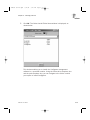
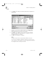
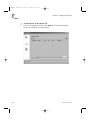
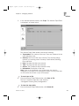
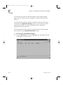
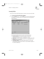
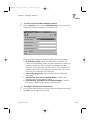
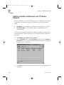
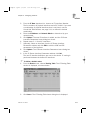
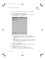
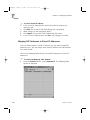
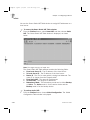
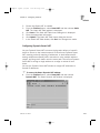
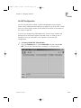
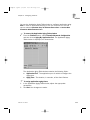
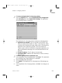
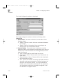
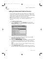
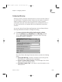
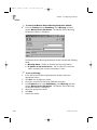
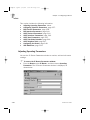
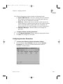
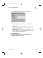
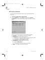
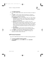
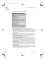
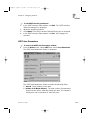
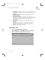
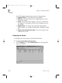
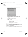
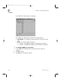
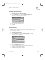
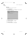
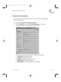
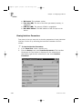
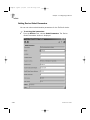
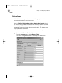
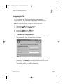
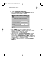
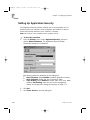
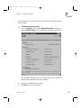
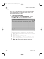
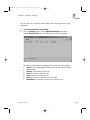
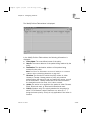
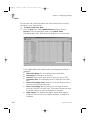
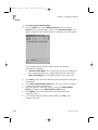
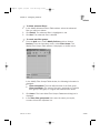
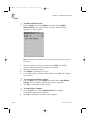
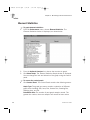
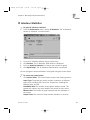
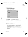
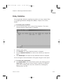
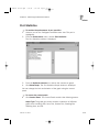
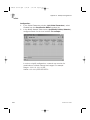
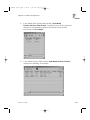
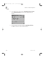
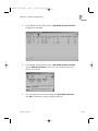
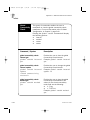
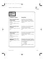
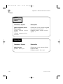
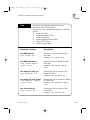
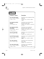
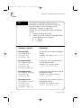
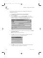
FPchapter 3.qxd 6/11/01 3:28 PM Page 3-112 Chapter 3 - Configuring FireProof ) 1. To modify a Diffserv policy: From the QoS menu, select Diffserv and then choose Modify Diffserv Policies. The Modify Diffserv Policies Table window is displayed, as shown below. Note: A definition of the field in this window are provided in the previous procedure. 2. 3. 4. 5. ) 1. 2. ) 1. 2. 3-112 Select the policy you require to edit and click Edit. The Modify Diffserv Policies Table Edit dialog box is displayed. Adjust the appropriate values. Click Update. The dialog box closes. In the Modify Diffserv Policies Table window click, Set. Your changes are recorded. To set the default Diffserv policies: From the QoS menu, select Diffserv and then choose Set Diffserv Policies. The Set Diffserv Policies dialog box is displayed. Click OK to set default Diffserv values. To update policy changes: From the QoS menu, select Update Policies. The Update Confirmation dialog box is displayed. Click OK to implement the latest policy changes. FireProof User Guide FPchapter 3.qxd 6/11/01 3:28 PM Page 3-113 Chapter 3 - Configuring FireProof Updating Software Radware may release updated versions of FireProof software. Upload these updated versions to benefit from increased functionality and performance. Software download can accessed be via Configware, or via ASCII terminal, refer to Appendix C for further details. A password is required when upgrading the software. The password is provided with the new software documentation. Note: If upload is not successful, current FireProof software does not change. If download is successful, new software is not implemented until you reset the device. Caution: Before uploading in VLAN regular mode, disable redundancy. ) 1. To upload software: From the File menu, select Software Download. The Update Device Software window is displayed. FireProof User Guide 3-113 FPchapter 3.qxd 6/11/01 3:29 PM Page 3-114 Chapter 3 - Configuring FireProof 2. 3. In the File Name field, enter the name of the file. Alternatively, click Browse to search the directory tree for the file. In the Password field, enter the password received with the new software version. Note: The password is case sensitive. 4. 5. 6. 3-114 Enter the software version number as specified in the new software documentation. Click Set. The status of the upload is displayed in the Progress Status field. You are prompted to restart the device. FireProof User Guide FP manual server.qxd 6/11/01 3:25 PM Page 4-1 P Monitoring FireProof Performance This chapter describes how to view performance graphs of your Radware network devices. You can graph statistics that show the performance of devices as a whole or of specific interfaces of the devices. The BadFrames SNMP counter of certain devices is automatically monitored, and by default you will be informed when an unusually high concentration of error frames occur. The relevant parameters are called the Threshold Parameters. You can modify the Threshold parameters, and you can also disable threshold reporting. The following sections are discussed in this chapter: z Element Statistics, page 4-2. z IP Interface Statistics, page 4-9. z Firewall Statistics, page 4-11. z Policy Statistics, page 4-13. z Port Statistics, page 4-15. FireProof User Guide 4-1 FP manual server.qxd 6/11/01 3:25 PM Page 4-2 Chapter 4 - Monitoring FireProof Performance Element Statistics ) To graph element statistics: 1. From the Performance menu, choose Element Statistics. The Element Statistics window is displayed, as shown below. 2. 3. From the Optional Counters list, choose the counters to graph. Click Show Graph. The Element Statistics Graph window is displayed. You can change the look and behavior of the graph using the control panel. To access the control panel: ) z Click Control Panel. The Control Panel contains the following menus: Graph Type: The graph type menu contains a selection of different graph views including: Bar, Area, Plot, Scatter Plot, Stacking Bar, Stacking Area, and Pie. Data Buffer Size: The number of past graph samples stored. The greater the number, the more samples are stored for later review. 4-2 FireProof User Guide FP manual server.qxd 6/11/01 3:25 PM Page 4-3 Chapter 4 - Monitoring FireProof Performance Monitor Size: The number of graph samples that are displayed on the screen. Sample Time: The amount of time between samples, in seconds. Presentation Units: The average number of events, per number of seconds entered here, based on the the total number of events recorded for the duration of the Sample Time. For example, if the Presentation Units is set as 1, and the Sample Time is set as 5, the graph will display the average number of events per 1 second based on the last 5 seconds of data. Changing the value of the Presentation Units will change the display of all graphs still in the buffer. To review the last compiled graph: ) z Click Show Last. The last graph that was compiled is displayed. The following counters can be graphed: Discarded IP datagrams due to header error The number of input datagrams discarded due to errors in their IP headers, including bad checksums, version number mismatch, other format errors, time-to-live exceeded, errors discovered in processing their IP options, etc." Discarded IP datagrams due to invalid address The number of input datagrams discarded because the IP address in their IP header's destination field was not a valid address to be received at this entity. This count includes invalid addresses (e.g., 0.0.0.0) and addresses of unsupported Classes (e.g., Class E). For entities which are not IP Gateways and therefore do not forward datagrams, this counter includes datagrams discarded because the destination address was not a local address. FireProof User Guide 4-3 FP manual server.qxd 6/11/01 3:25 PM Page 4-4 Chapter 4 - Monitoring FireProof Performance 4-4 Discarded IP datagrams that were received correctly The number of input datagrams that were received correctly. Input IP datagrams discarded -protocol problems The number of locally-addressed datagrams received successfully but discarded because of an unknown or unsupported protocol. Input IP datagrams forwarded The number of input datagrams for which this entity was not their final IP destination, as a result of which an attempt was made to find a route to forward them to that final destination. In entities which do not act as IP Gateways, this counter will include only those packets which were SourceRouted via this entity, and the Source Route option processing was successful. IP datagram fragments generated The number of IP datagram fragments that have been generated as a result of fragmentation at this entity. IP datagrams successfully fragmented The number of IP datagrams that have been successfully fragmented at this entity. IP datagrams discarded not fragmented The number of IP datagrams that have been discarded because they needed to be fragmented at this entity but could not be, e.g., because their Don't Fragment flag was set. FireProof User Guide FP manual server.qxd 6/11/01 3:25 PM Page 4-5 Chapter 4 - Monitoring FireProof Performance IP fragments failed reassembly The number of failures detected by the IP re-assembly algorithm (for whatever reason: timed out, errors, etc). Note that this is not necessarily a count of discarded IP fragments since some algorithms (notably the algorithm in RFC 815) can lose track of the number of fragments by combining them as they are received. IP fragments successfully reassembled The number of IP datagrams successfully re-assembled. IP fragments received need reassembly The number of IP fragments received which needed to be reassembled at this entity. Outgoing discarded IP datagrams that have no error The number of output IP datagrams for which no problem was encountered to prevent their transmission to their destination, but which were discarded (e.g., for lack of buffer space). Note that this counter would include datagrams counted in ipForwDatagrams if any such packets met this (discretionary) discard criterion. Output IP datagrams discarded - no route found The number of IP datagrams discarded because no route could be found to transmit them to their destination. Note that this counter includes any packets counted in ipForwDatagrams which meet this `no-route' criterion. Note that this includes any datagarms which a host cannot route because all of its default gateways are down. FireProof User Guide 4-5 FP manual server.qxd 6/11/01 3:25 PM Page 4-6 Chapter 4 - Monitoring FireProof Performance 4-6 Resource Utilization The percent of the device's CPU currently utilized. RIP - changes made to IP Route Database The number of changes made to the IP Route Database by RIP. RIP - global responses sent to RIP queries The number of responses sent to RIP queries from other systems. SNMP 'get' requests retrieved successfully The total number of MIB objects which have been retrieved successfully by the SNMP protocol entity as the result of receiving valid SNMP Get-Request and Get-Next PDUs. SNMP 'Get-Next' PDUs processed The total number of SNMP Get-Request PDUs which have been accepted and processed by the SNMP protocol entity. SNMP 'Get-Request' PDUs processed The total number of SNMP Get-Request PDUs which have been accepted and processed by the SNMP protocol entity. SNMP 'set' requests retrieved successfully The total number of MIB objects which have been altered successfully by the SNMP protocol entity as the result of receiving valid SNMP Set-Request PDUs. SNMP 'Set-Request' PDUs processed The total number of SNMP Set-Request PDUs which have been accepted and processed by the SNMP protocol entity. SNMP generated 'Get-Response' PDUs The total number of SNMP GetResponse PDUs which have been generated by the SNMP protocol entity. FireProof User Guide FP manual server.qxd 6/11/01 3:25 PM Page 4-7 Chapter 4 - Monitoring FireProof Performance SNMP generated 'Trap' PDUs The total number of SNMP Trap PDUs which have been generated by the SNMP protocol entity. SNMP output PDUs 'badValues' The total number of SNMP PDUs which were generated by the SNMP protocol entity and for which the value of the error-status field is 'badValue'. SNMP output PDUs 'genErr' The total number of SNMP PDUs which were generated by the SNMP protocol entity and for which the value of the error-status field is 'genErr'. SNMP output PDUs 'noSuchName' The total number of SNMP PDUs which were generated by the SNMP protocol entity and for which the value of the error-status is 'noSuchName'. SNMP output PDUs 'tooBig' The total number of SNMP PDUs which were generated by the SNMP protocol entity and for which the value of the error-status field is 'tooBig.' The total number of input datagrams successfully delivered to IP userprotocols (including ICMP). Successfully delivered IP datagrams Total IP datagrams queued for transmission FireProof User Guide The total number of IP datagrams which local IP user-protocols (including ICMP) supplied to IP in requests for transmission. Note that this counter does not include any datagrams counted in ipForwDatagrams. 4-7 FP manual server.qxd 6/11/01 3:25 PM Page 4-8 Chapter 4 - Monitoring FireProof Performance 4-8 Total number of incoming IP datagrams The total number of input datagrams received from interfaces, including those received in error. Total SNMP messages received The total number of Messages delivered to the SNMP entity from the transport service. Total SNMP output messages passed The total number of SNMP Messages, which were passed from the SNMP protocol entity to the transport service. FireProof User Guide FP manual server.qxd 6/11/01 3:25 PM Page 4-9 Chapter 4 - Monitoring FireProof Performance IP Interface Statistics ) To graph IP interface statistics: 1. From the Performance menu, choose IP Statistics. The IP Statistics window is displayed, as shown below. 2. 3. 4. 5. From the IP Statistics window, select a table entry. Click Perform. The IP Statistics Table window is displayed. From the Optional Counters list, choose the counters to graph. Click Show Graph. The IP Statistics Graph window is displayed. You can change the look and behavior of the graph using the control panel. To access the control panel: ) z Click Control Panel. The Control Panel contains the following menus: Graph Type: The graph type menu contains a selection of different graph views including: Bar, Area, Plot, Scatter Plot, Stacking Bar, Stacking Area, and Pie. Data Buffer Size: The number of past graph samples stored. The greater the number, the more samples are stored for later review. Monitor Size: The number of graph samples that are displayed on the screen. Sample Time: The amount of time between samples, in seconds. FireProof User Guide 4-9 FP manual server.qxd 6/11/01 3:25 PM Page 4-10 Chapter 4 - Monitoring FireProof Performance Presentation Units: The average number of events, per number of seconds entered here, based on the the total number of events recorded for the duration of the Sample Time. For example, if the Presentation Units is set as 1, and the Sample Time is set as 5, the graph will display the average number of events per 1 second based on the last 5 seconds of data. Changing the value of the Presentation Units will change the display of all graphs still in the buffer. To review the last compiled graph: ) z Click Show Last. The last graph that was compiled is displayed. The following counters can be graphed: 4-10 Interface's RIP - response packets discarded The number of RIP response packets received by the RIP process which were subsequently discarded for any reason (e.g. a version 0 packet, or an unknown command type). Interface's RIP routes ignored The number of routes, in valid RIP packets, which were // ignored for any reason (e.g. unknown address family, or invalid metric). Interface's RIP updates sent The number of triggered RIP updates actually sent on this interface. This explicitly does NOT include full updates sent containing new information. FireProof User Guide FP manual server.qxd 6/11/01 3:25 PM Page 4-11 Chapter 4 - Monitoring FireProof Performance Firewall Statistics ) To monitor application statistics: 1. From the Performance menu, choose Firewall Statistics. The Firewall Statistics window is displayed. 2. 3. 4. 5. Select a server farm. Click Perform. The Firewall Statistics window opens. From the Optional Counters list, choose the counters to graph. Click Show Graph. The Device Application Specifics Graph is displayed. You can change the look and behavior of the graph using the control panel. To access the control panel: ) z Click Control Panel. The Control Panel contains the following menus: Graph Type: The graph type menu contains a selection of different graph views including: Bar, Area, Plot, Scatter Plot, Stacking Bar, Stacking Area, and Pie. Data Buffer Size: The number of past graph samples stored. The greater the number, the more samples are stored for later review. Monitor Size: The number of graph samples that are displayed on the screen. Sample Time: The amount of time between samples, in seconds. FireProof User Guide 4-11 FP manual server.qxd 6/11/01 3:25 PM Page 4-12 Chapter 4 - Monitoring FireProof Performance To review the last compiled graph: ) z Click Show Last. The last graph that was compiled is displayed. The following counters can be graphed: 4-12 Active users Number of currently active users attached to this firewall. Frames peak rate Maximum number of frames per second dispatched to the firewall since the last reset. Frames current rate Number of frames per second dispatched to the firewall. Frames maximum rate Maximal number of frames per second dispatched to the firewall. FireProof User Guide FP manual server.qxd 6/11/01 3:25 PM Page 4-13 Chapter 4 - Monitoring FireProof Performance Policy Statistics You can generate statistics regarding the policies you have created. Refer to Configuring Bandwidth Management (BWM) in Chapter 3 for further details. ) To monitor policy statistics: 1. From the Performance menu, choose Policy Statistics. The Active Policies Selection Table window is displayed. 2. 3. 4. Select a policy name. Click Perform. The Policy Statistics window is displayed. From the Optional Counters list, choose the counters you require to graph. Click Show Graph. The Graph of Policy Statistics window is displayed. 5. You can change the look and behavior of the graph using the control panel. To access the control panel: ) z Click Control Panel. The Control Panel contains the following menus: Graph Type: The graph type menu contains a selection of different graph views including: Bar, Area, Plot, Scatter Plot, Stacking Bar, Stacking Area, and Pie. FireProof User Guide 4-13 FP manual server.qxd 6/11/01 3:25 PM Page 4-14 Chapter 4 - Monitoring FireProof Performance Data Buffer Size: The number of past graph samples stored. The greater the number, the more samples are stored for later review. Monitor Size: The number of graph samples that are displayed on the screen. Sample Time: The amount of time between samples, in seconds. To review the last compiled graph: ) z Click Show Last. The last graph that was compiled is displayed. The following counters can be graphed: 4-14 Average Bandwidth Displays the average amount of bandwidth used by the selected policy. Peak Average Bandwidth Displays the peak average amount of bandwidth used by the selected policy. Used Bandwidth Displays the amount of bandwidth used by the selected policy. FireProof User Guide FP manual server.qxd 6/11/01 3:25 PM Page 4-15 Chapter 4 - Monitoring FireProof Performance Port Statistics ) To monitor the performance of port specifics: 1. 2. 3. 4. Select a port on the Configware software zoom view. The port is highlighted. From the Performance menu, choose Port Statistics. The Port Statistics window is displayed. From the Optional Counters list, choose the counters to graph. Click Show Graph. The Port Statistics Graph window is displayed. You can change the look and behavior of the graph using the control panel. To access the control panel: ) z Click Control Panel. The Control Panel contains the following menus: Graph Type: The graph type menu contains a selection of different graph views including: Bar, Area, Plot, Scatter Plot, Stacking Bar, Stacking Area, and Pie. FireProof User Guide 4-15 FP manual server.qxd 6/11/01 3:25 PM Page 4-16 Chapter 4 - Monitoring FireProof Performance Data Buffer Size: The number of past graph samples stored. The greater the number, the more samples are stored for later review. Monitor Size: The number of graph samples that are displayed on the screen. Sample Time: The amount of time between samples, in seconds. Presentation Units: The average number of events, per number of seconds entered here, based on the the total number of events recorded for the duration of the Sample Time. For example, if the Presentation Units is set as 1, and the Sample Time is set as 5, the graph will display the average number of events per 1 second based on the last 5 seconds of data. Changing the value of the Presentation Units will change the display of all graphs still in the buffer. To review the last compiled graph: ) z Click Show Last. The last graph that was compiled is displayed. The following counters can be graphed: 4-16 Subnetwork-unicast packets delivered The number of subnetwork-unicast packets delivered to a higher-layer protocol. Input non-unicast packets The number of non-unicast (i.e., subnetwork- broadcast or subnetworkmulticast) packets delivered to a higher-layer protocol. Input discarded packets fine packets The number of inbound packets which were chosen to be discarded even though no errors had been detected to prevent their being deliverable to a higher-layer protocol. One possible reason for discarding such a packet could be to free up buffer space. FireProof User Guide FP manual server.qxd 6/11/01 3:25 PM Page 4-17 Chapter 4 - Monitoring FireProof Performance Input packets with errors, not delivered Input discarded packets protocol problems The number of inbound packets that contained errors preventing them from being deliverable to a higher-layer protocol. The number of packets received via the interface which were discarded because of an unknown or unsupported protocol. Output subnetwork-unicast packets The total number of packets that higher-level protocols requested be transmitted to a subnetwork-unicast address, including those that were discarded or not sent. Output non-unicast packets The total number of packets that higher-level protocols requested be transmitted to a non- unicast (i.e., a subnetwork-broadcast or subnetworkmulticast) address, including those that were discarded or not sent. Output discarded packets fine packets The number of outbound packets which were chosen to be discarded even though no errors had been detected to prevent their being transmitted. One possible reason for discarding such a packet could be to free up buffer space. Packets with errors, not transmitted The number of outbound packets that could not be transmitted because of errors. FireProof User Guide 4-17 FP manual server.qxd 6/11/01 3:25 PM Page 4-18 FP manual server.qxd 6/11/01 3:25 PM Page A-1 APPENDIX a Example Configurations This chapter discusses FireProof example configurations. The following examples are included: z Example 1: Simple FireProof Configuration, page A-2. z Example 2: VLAN Configuration, page A-4. z Example 3: One Leg (Lollipop) Configuration, page A-6. z Example 4: Typical FireProof Configuration, page A-8. z Example 5: Redundant FireProof Configuration, page A-11. z Example 6: Redundant FireProof Configuration Using VLAN, z page A-14. z Example 7: DMZ Support with Port Connectivity Rules, page A-17. z Example 8: Application Grouping with FireProof, page A-19. z Example 9: QoS Used for Access Control, page A-21. z Example 10: Bandwidth Management, page A-25. z Example 11: Application Security, page A-29. FireProof User Guide A-1 FP manual server.qxd 6/11/01 3:25 PM Page A-2 Appendix A - Example Configurations Example 1: Simple FireProof Configuration Router 100.1.1.10 100.1.1.2 Firewall 2 100.1.1.1 Firewall 1 20.1.1.2 port 2 20.1.1.1 20.1.1.10 FireProof port 1 10.1.1.10 Local Network 10.1.1.X Figure A-1: Local Network and Firewalls on Different Subnets A-2 FireProof User Guide FP manual server.qxd 6/11/01 3:25 PM Page A-3 Appendix A - Example Configurations Properties: z The Local Network Side and the Firewall Side are on different subnets. z Firewalls must be configured with the Network Address Translation feature enabled, in order to ensure return traffic uses the correct firewall for each session. z The firewalls can be proxy firewalls. In this case, make use of a virtual IP to represent the proxy address of the firewalls for the configured clients. Configuration: 1. Define two IP interfaces on the FireProof. One with a 10.1.1.10 address on port 1 and one with a 20.1.1.10 address on port 2. 2. In the Firewalls Table window (FireProof/Firewall Table), insert firewalls 20.1.1.1 and 20.1.1.2. 3. The default router of the FireProof should be one of the firewall's internal interfaces (for example 20.1.1.1). The next hop router of the firewalls for the local network should be the 20.1.1.10 address of the FireProof assigned to port 2. Default router for the Local side should be the FireProof internal address (10.1.1.10). 4. In the Global Configuration window (FireProof/Global Configuration), adjust the Dispatch Method and the Connectivity Check configuration, as required. 5. It is recommended to use Full Path Health Monitoring to ensure the remote side of the firewall is operational. In the Firewall Table window (FireProof/Firewall Table), select a firewall and click Full Path Health Monitoring. For example, configure the router at 100.1.1.10 as the Check Address for each of the firewalls. 6. When proxy firewalls are used, a Virtual IP should be configured, as discussed in Chapter 3: a. In the Virtual IP Table window (FireProof/Virtual IP), insert a virtual IP address, for example 10.1.1.100. The clients should be configured to use that address as the proxy address. b. In the Virtual IP Table window, select the vitual IP address and click Opens Mapped Table, or select Mapped IP from the FireProof menu. For each Firewall IP address, insert the firewall IP and for each Firewall NAT address insert the Firewall IP as well. FireProof User Guide A-3 FP manual server.qxd 6/11/01 3:25 PM Page A-4 Appendix A - Example Configurations Example 2: VLAN Configuration Router 100.1.1.10 100.1.1.12 Firewall 2 100.1.1.11 Firewall 1 10.1.1.12 10.1.1.11 FireProof 10.1.1.10 Local Network 10.1.1.X Figure A-2: Local Network and Firewall on Same Subnet A-4 FireProof User Guide FP manual server.qxd 6/11/01 3:25 PM Page A-5 Appendix A - Example Configurations Properties: z The Local Network Side and the Firewall Side are on the same IP subnet. z Firewalls must be configured with the Network Address Translation feature enabled, in order to ensure return traffic uses the correct firewall for each session. Configuration: 1. Define an IP VLAN that includes ports 1 and 2. The FireProof includes an IP VLAN by default. This VLAN can be edited to include ports 1 and 2, or an entirely new VLAN can be configured. VLANs are configured in the Virtual LAN Table window (Device/VLAN). Note: To operate the load balancing in a VLAN network topology you must set your VLAN to be a "Regular" VLAN type. 2. 3. 4. 5. 6. Define an IP interface with the address 10.1.1.10 to be associated with the VLAN defined in step 1 above. If there is an existing IP interface with a 10.1.1.10 address, it should be edited so that the 10.1.1.10 address is associated with the VLAN. If there is no existing IP interface with a 10.1.1.10 address, one must be created. In the Firewalls Table window (FireProof/Firewall Table), insert firewalls 10.1.1.11 and 10.1.1.12. The default router of the FireProof should be one of the firewall's internal interfaces, for example 10.1.1.11. The default gateway of clients on the 10.1.1.X subnet should be the FireProof at 10.1.1.10. No route to 10.1.1.X is required on the firewalls. It is recommended to use Full Path Health Monitoring to ensure the remote side of the firewall is operational. In the Firewall Table window (FireProof/Firewall Table), select a firewall and click Full Path Health Monitoring. For example, configure the router at 100.1.1.10 as the Check Address for each of the firewalls. FireProof User Guide A-5 FP manual server.qxd 6/11/01 3:25 PM Page A-6 Appendix A - Example Configurations Example 3: One Leg (Lollipop) Configuration Router 20.1.1.100 Firewall 2 Firewall 1 20.1.1.2 20.1.1.10 10.1.1.10 20.1.1.1 10.1.1.X FireProof Local Network Figure A-3 - Local Network Subnet and Firewall Subnet on the same LAN A-6 FireProof User Guide FP manual server.qxd 6/11/01 3:25 PM Page A-7 Appendix A - Example Configurations Properties: z The Local Network Side Subnet and the Firewall Side Subnet are on the same LAN. All connections can be made to the same switch. z Firewalls must be configured with the Network Address Translation feature enabled, in order to ensure return traffic uses the correct firewall for each session. Configuration: 1. Define two IP interfaces on port 1 of the FireProof. The first with IP address 10.1.1.10 and the second with IP address 20.1.1.10, then make sure both IP addresses are associated with port 1. 2. In the Firewalls Table window (FireProof/Firewall Table), insert firewalls 20.1.1.1 and 20.1.1.2. 3. The default router of the FireProof should be one of the firewall's internal interfaces, for example 20.1.1.1. The router of the firewalls for the local network should be the 20.1.1.10 address of the FireProof. The default router for the Local Network should be the FireProof address (10.1.1.10). 4. It is recommended to use Full Path Health Monitoring to ensure the remote side of the firewall is operational. In the Firewall Table window (FireProof/Firewall Table), select a firewall and click Full Path Health Monitoring. For example, configure the router at 20.1.1.100 as the Check Address for each of the firewalls. FireProof User Guide A-7 FP manual server.qxd 6/11/01 3:25 PM Page A-8 Appendix A - Example Configurations Example 4: Typical FireProof Configuration 100.1.1.20 100.1.1.10 FireProof 2 30.1.1.10 NAT: 30.1.1.31 for 10.1.1.30 30.1.1.2 Firewall 2 30.1.1.1 NAT: 30.1.1.30 for 10.1.1.30 Firewall 1 20.1.1.2 20.1.1.1 20.1.1.10 FireProof 1 10.1.1.10 10.1.1.30 Local Network 10.1.1.X Figure A-4 - Typical FireProof Configuretion A-8 FireProof User Guide FP manual server.qxd 6/11/01 3:25 PM Page A-9 Appendix A - Example Configurations Properties: z Typical configuration when inbound traffic is required to servers on the local subnet, with or without NAT configured for the firewalls. z The Local Network Side and the Firewall Side are on different subnets. z The firewalls can be configured with NAT for all the clients on the local network, or for some of them. This configuration caters to transparent firewalls and firewalls that implement NAT. z When static NAT is used on the firewalls, a virtual IP address is created on the external FireProof to ensure that different NAT addresses, on different firewalls, for a single internal host, are seen as a single public address. This provides load balancing and high availability between the NAT addresses. Configuration: 1. Define two IP interfaces on FireProof #1. One with a 10.1.1.10 address and one with a 20.1.1.10 address. 2. In the Firewall Table window (FireProof/Firewall Table), on FireProof #1. Insert firewalls 20.1.1.1 and 20.1.1.2. 3. Define two IP interfaces on FireProof #2 similarly. One with a 30.1.1.10 address, and one with a 100.1.1.10 address. 4. In the Firewall Table window (FireProof/Firewall Table), on FireProof #2. Insert firewalls 30.1.1.1 and 30.1.1.2. z The router of FireProof #2 for the local network should be one z of the firewalls, for example 30.1.1.1, and its default gateway to z the Internet is the access router 100.1.1.20. z The router of the firewalls for the local network should be the z 20.1.1.10 address of FireProof #1. z The default router of the firewalls (to connect to the internet) z z should be the FireProof #2 internal address, for example z z z 30.1.1.10. z The default router of FireProof #1 should be one of the firewall's z internal addresses,for example 20.1.1.1. z The route of the access router to the local network should be z z FireProof #2 external address (100.1.1.10). z The default router of the local network should be FireProof #1 z address (10.1.1.10). FireProof User Guide A-9 FP manual server.qxd 6/11/01 3:25 PM Page A-10 Appendix A - Example Configurations 5. 6. 7. A-10 If the firewalls use static NAT addresses, configure a virtual IP address in the Virtual IP table of FireProof #2. This is necessary in order to have one public address for each server, rather than as many public IP addresses as the number of firewalls. Using VIP on the external FireProof assures that this single public IP is always online and is load balanced among the firewalls. a. In the Virtual IP Table window (Device/VLAN), insert a virtual IP address, for example 10.1.1.100. This is the public IP address representing the internal server 10.1.1.30. b. In the Virtual IP Table window (Device/VLAN), select the virtual IP address and click Opens Mapped Table, or select Mapped IP from the FireProof menu. For each Firewall IP address, insert the firewall IP and for each Firewall NAT address insert the Firewall NAT for the server. For example, NAT 30.1.1.30 for firewall #1 and NAT 30.1.1.31 for firewall #2 When proxy firewalls are used, a Virtual IP should be configured on FireProof #1. It is recommended to use Full Path Health Monitoring to ensure the remote side of the firewall is operational. In the Firewall Table window (FireProof/Firewall Table), select a firewall and click Full Path Health Monitoring. For example, configure the internal IP of FireProof #2 30.1.1.10 as the Check Address for each of the firewalls configured in FireProof #1, and vice versa. Use IP 20.1.1.10 for the Check Address of the firewalls configured in FireProof #2. FireProof User Guide FP manual server.qxd 6/11/01 3:25 PM Page A-11 Appendix A - Example Configurations Example 5: Redundant FireProof Configuration Firewall 2 Firewall 1 20.1.1.2 20.1.1.1 20.1.1.11 20.1.1.10 FireProof 1 Primary FireProof 2 Backup 10.1.1.11 10.1.1.10 10.1.1.X Local Network Figure A-5 - Redundant FireProof Units FireProof User Guide A-11 FP manual server.qxd 6/11/01 3:25 PM Page A-12 Appendix A - Example Configurations Properties: z The Local Network Side and the Firewall Side are on different subnets. z Firewalls must be configured with the Network Address Translation feature enabled. Note: Only the primary FireProof is active; the backup is idle. The reason for this is that the local network can have only one of the FireProof units configured as its default router (FireProof #1 in this case), so traffic coming from FireProof #2 will not be returned through it but through FireProof #1. FireProof #1 does not hold session information about sessions that were sent via FireProof #2, and thus is unable to send it back to the firewalls correctly. If FireProof #1 fails, and FireProof #2 is configured as its backup, the traffic will be managed by FireProof #2. The firewall will still send the traffic to its next hop router, but FireProof #2 will take over the failing FireProof #1 IP addresses, and handle the traffic correctly. Configuration: 1. Define two IP interfaces on FireProof #1. One with a 10.1.1.10 address on port 1 and one with a 20.1.1.10 address on port 2. 2. In the Firewall Table window (FireProof/Firewall Table), insert firewalls 20.1.1.1 and 20.1.1.2. 3. Define two IP interfaces on FireProof #2 similarly. One with a 10.1.1.11 address on port 1, and one with a 20.1.1.11 address on port 2. 4. Follow step 2 to configure the firewalls on FireProof #2. All parameters for firewalls should be similar to those configured on FireProof #1, in particular the Firewall Mode should be Regular. 5. Define FireProof #2 interfaces as redundant to those of FireProof #1. In the IP Redundancy Table window (FireProof/ Redundancy/IP Redundancy Table) of FireProof #2, enter 10.1.1.11 and 20.1.1.11 as the interface addresses, and 10.1.1.10 and 20.1.1.10 as the main addresses, respectively. 6. Set the Global Redundancy Configuration for FireProof #1: In the Global Redundancy Configuration window (FireProof/Redundancy/ Global Configuration), set the IP Redundancy Status to Disabled and the Interface Grouping to Enabled. A-12 FireProof User Guide FP manual server.qxd 6/11/01 3:25 PM Page A-13 Appendix A - Example Configurations 7. 8. 9. Set the Global Redundancy Configuration for FireProof #2: In the Global Redundancy Configuration window (FireProof/Redundancy/ Global Configuration), set the IP Redundancy Status to Enabled and the Interface Grouping to Disabled. The default router of both FireProof units should one of the firewall's internal addresses (for example: 20.1.1.1). The router of the firewalls for the local network should be the 20.1.1.10 address of FireProof #1. The default router of the local network should be the 10.1.1.10 address of FireProof #1. It is recommended to use Full Path Health Monitoring to ensure the remote side of the firewall is operational. In the Firewall Table window (FireProof/Firewall Table), select a firewall and click Full Path Health Monitoring. FireProof User Guide A-13 FP manual server.qxd 6/11/01 3:25 PM Page A-14 Appendix A - Example Configurations Example 6: Redundant FireProof Configuration Using VLAN Firewall 2 Firewall 1 10.1.1.2 FireProof 2 Backup 10.1.1.11 10.1.1.1 FireProof 1 Primary 10.1.1.10 10.1.1.X Local Network Figure A-6 - DMZ Support with Port Connectivity Rules A-14 FireProof User Guide FP manual server.qxd 6/11/01 3:25 PM Page A-15 Appendix A - Example Configurations Properties: z The Local Network side and the Next Hop Router side are on the same subnet. Note: Only the primary FireProof is active; the backup is idle. The reason for this is that each host on the local subnet can have a single default gateway, and the same is true for each of the routers, a single next hop router towards the internal subnet. The FireProof must see all the packets from every session, in order to make sure a single firewall is used for each session. The internal hosts and the firewalls should all use the same FireProof as their gateway. If FireProof #1 fails, and FireProof #2 is configured as its backup, the traffic will be managed by FireProof #2. The next hop router will still send the traffic to its router, but FireProof #2 will take over the failing FireProof #1 IP addresses, and handle the traffic correctly. Active FireProof Configuration (FireProof #1): 1. Define an IP VLAN that includes ports 1 and 2. The FireProof includes an IP VLAN by default. This VLAN can be edited to include ports 1 and 2, or an entirely new VLAN can be configured. VLANs are configured in the Virtual LAN Table window (Device/VLAN). Note: To operate the load balancing in a VLAN network topology you must set your VLAN to be a Regular VLAN type. 2. 3. 4. Define an IP interface with the address 10.1.1.10 to be associated with the VLAN defined in step 1 above. If there is an existing IP interface with a 10.1.1.10 address, it should be edited so that this address is associated with the VLAN. If there is no existing IP interface with a 10.1.1.10 address, one must be created. In the Firewall Table window (FireProof/Firewall Table), insert firewalls 10.1.1.1 and 10.1.1.2. Configure Full Path Health Monitoring, as required. In the Global Redundancy Configuration window (FireProof/ Redundancy/Global Configuration), ensure that in the Interface Grouping field is Enabled and the IP Redundancy Admin Status field is Disabled. Ensure that in the VLAN Redundancy Device Mode is set to Active. Refer to page 3-41, for further details about Global Configuration parameters. FireProof User Guide A-15 FP manual server.qxd 6/11/01 3:25 PM Page A-16 Appendix A - Example Configurations Backup FireProof Configuration (FireProof #2): 1. Define an IP VLAN that includes ports 1 and 2. VLANs are configured in the Virtual LAN Table window (Device/VLAN). Note: To operate the load balancing in a VLAN network topology you must set your VLAN to be a Regular VLAN type. 2. 3. 4. 5. Define an IP interface with the address 10.1.1.11 to be associated with the VLAN defined in step 1 above. If there is an existing IP interface with a 10.1.1.11 address, it should be edited so that this address is associated with the VLAN. If there is no existing IP interface with a 10.1.1.11 address, one must be created. In the Firewall Table window (FireProof/Firewall Table), insert firewalls 10.1.1.1 and 10.1.1.2. Make sure Firewall Mode is set to Regular. Configure Full Path Health Monitoring, as required. In the Global Redundancy Configuration window (FireProof/ Redundancy/Global Configuration), ensure that in the Interface Grouping field is Disabled, and the IP Redundancy Admin Status field is Enabled. Ensure that the VLAN Redundancy Device Mode is set to Backup. Define FireProof #2 interfaces as redundant to those of FireProof #1. In the IP Redundancy Table window (FireProof/Redundancy/IP Redundancy Table) of FireProof #2, enter 10.1.1.11 for the interface address and 10.1.1.10 as the main device IP address. Notes: 1. In advanced configuration, any IP addresses owned by the main device, besides its interfaces IP addresses, such as NAT or VIP, should be configured similarly on the backup device, with Redundancy Mode set to Backup. 2. When using layer 3 switches between the FireProof devices, the Backup Fake ARP parameter might need to be changed. Refer to page 3-46 for further information. A-16 FireProof User Guide FP manual server.qxd 6/11/01 3:25 PM Page A-17 Appendix A - Example Configurations Example 7: DMZ Support with Port Connectivity Rules 200.1.1.10 200.1.1.2 200.1.1.1 Firewall 1 Firewall 2 20.1.1.2 110.1.1.2 20.1.1.1 110.1.1.1 Hub Hub FireProof 3 2 20.1.1.10 10.1.1.10 110.1.1.10 1 4 10.1.1.X 100.1.1.10 100.1.1.X Local Network Figure A-7 - DMZ Support with Port Connectivity Rules FireProof User Guide A-17 FP manual server.qxd 6/11/01 3:25 PM Page A-18 Appendix A - Example Configurations Properties: z The Local Network and the DMZ are on different subnets. z Each firewall has 3 interfaces: external, internal and DMZ. Load balancing is required for the DMZ and internal sides. Typically two devices can be used, however the same functionality can be acheived using a single device and port rules. z Firewalls should be configured with the Network Address Translation feature enabled, or an external FireProof can be used. Configuration: 1. Define four IP interfaces on FireProof. One with a 10.1.1.10 address on port 1, one with a 20.1.1.10 address on port 2, one with a 110.1.1.10 address on port 3 and one with a 100.1.1.10 address on port 4. 2. In the Firewall Table window (FireProof/Firewall Table), insert firewalls 20.1.1.1, 20.1.1.2, 110.1.1.1 and 110.1.1.2. 3. Define FireProof port rules that ensure that traffic to and from port 1 arrives and exits only via port 2; and that traffic to and from port 3 arrives and exits only via port 4. This ensures separation of the DMZ and the local network. This configuration is available only from the console, type: “rules set 1 2“, and “rules set 3 4“. z The default router of the FireProof should be one of the firewalls. z No further routes are required for the FireProof as the port rules z dictate the routing behavior of the FireProof. z The router of the firewalls for the local network should be the z z 20.1.1.10 address of the FireProof. z The router of the firewalls for the DMZ should be the 110.1.1.10 z z address of the FireProof. z The default router of the firewalls to the Internet should be the z z access router, 200.1.1.10. z The default router of the local network to the Internet should be z z the 10.1.1.10 address on port 1 of the FireProof. z The default router for the DMZ to the Internet is the 100.1.1.10 z z address on port 4 of the FireProof. A-18 FireProof User Guide FP manual server.qxd 6/11/01 3:25 PM Page A-19 Appendix A - Example Configurations Example 8: Application Grouping with FireProof Mail servers Firewall 1 Firewall 2 Firewall 3 20.1.1.1 20.1.1.2 20.1.1.3 20.1.1.10 FireProof 10.1.1.10 Local clients 10.1.1.X FireProof User Guide A-19 FP manual server.qxd 6/11/01 3:25 PM Page A-20 Appendix A - Example Configurations Properties: z Three firewalls are used, one of them protects access to the mail servers, the other two protect traffic to and from the Internet. z Different aging may be required for mail traffic. Configuration: 1. Configure FireProof with the following IP addresses 10.1.1.10 and 20.1.1.10, for the required ports. 2. Configure the firewalls with the following addresses 20.1.1.1, 20.1.1.2 and 20.1.1.3 in the Firewall Table window, (FireProof/Firewall Table). 3. Configure the FireProof to send mail traffic only to firewall #3. In the Application Port Grouping window (FireProof/Firewalls Advanced Configuration/Grouping/Application Grouping), insert the Application Port Number, for example, SMTP, or type 25, and the Firewall IP Address, for example, 20.1.1.3. 4. If different aging is required for mail traffic, configure this in the Application Aging Table window (FireProof/Firewalls Advanced Configuration/Aging by Application Port). In the Application Port field, select SMTP, or type 25. In the Aging Time field, select the required aging. 5. In the Global Configuration window (FireProof/Global Configuration), set Client Mode to Layer 4 in the Client Table tab, and set Open New Entry for Different Source Port to Enabled. A-20 FireProof User Guide FP manual server.qxd 6/11/01 3:25 PM Page A-21 Appendix A - Example Configurations Example 9: QoS Used for Access Control Server X 200.1.1.1 Firewall 1 20.1.1.1 Firewall 2 20.1.1.2 20.1.1.10 FireProof 10.1.1.10, 11.1.1.10 10.1.1.X 11.1.1.X 10.1.1.4 Properties: z Server X at IP address 200.1.1.1 can communicate to the internal server using telnet or FTP. Otherwise, the server can be accessed using HTTP only. z Internal users cannot access the 200.1.1.1 server. z All other traffic through the device is blocked. FireProof User Guide A-21 FP manual server.qxd 6/11/01 3:25 PM Page A-22 Appendix A - Example Configurations Configuration: 1. In the Global Parameters window, (QoS/Global Parameters), select Enabled from the Classification Mode dropdown list. 2. In the Modify Network Table window, (QoS/Modify Policies/Networks), configure network for the local network. For example: In order to simplify configuration, a network can consist of a combination of network subnets and ranges. For example: Range = 11.1.1.0 - 11.1.1.255 Subnet = 10.1.1.0/255.255.255.0 A-22 FireProof User Guide FP manual server.qxd 6/11/01 3:25 PM Page A-23 Appendix A - Example Configurations 3. In the Modify Filter Groups Table window, (QoS/Modify Policies/Services/Filter Groups). Configure a group for the protocols allowed for communication between the remote server and the internal server. For example: 4. In the Modify Policies Table window, (QoS/Modify Policies/Policies). configure the following, for example: FireProof User Guide A-23 FP manual server.qxd 6/11/01 3:25 PM Page A-24 Appendix A - Example Configurations A-24 5. In the Modify Policies Table window, (QoS/Modify Policies/Policies). use the Edit Default Policy button to set the default Action, as required. 6. From the Update Confirmation dialog box (QoS/Update Policies), click OK to activate the newly configured policies. FireProof User Guide FP manual server.qxd 6/11/01 4:51 PM Page A-25 Appendix A - Example Configurations Example 10: Bandwidth Management Subnet X 222.2.2.0 Router Firewall 2 Firewall 1 FireProof 10.1.1.4-6 FireProof User Guide Local Network 10.1.1.X A-25 FP manual server.qxd 6/11/01 3:25 PM Page A-26 Appendix A - Example Configurations Note: SynApps license is required to access this functionality. Properties: z SMTP to the servers has highest priority. z HTTP has higher priority than SMTP. z HTTP traffic to users at subnet 222.2.2.0 has a low priority. z FTP is limited to 200Kbit/s, and has a low priority. Configuration: 1. In the Global Parameters window, (QoS/Global Parameters), select Policies from the Classification Mode dropdown list. 2. In the Modify Network Table window, (QoS/Modify Policies/Networks), configure network for the local servers. In order to simplify configuration, a network can consist of a combination of network subnets and ranges. For example, the servers’ NAT consists of two ranges 201.11.11.4-6 and 202.22.22.4-6. A-26 FireProof User Guide FP manual server.qxd 6/11/01 3:25 PM Page A-27 Appendix A - Example Configurations 3. In the Modify Policies Table window, (QoS/Modify Policies/Policies), configure the following. 4. In the Modify Policies Table window, (QoS/Modify Policies/Policies), use the Edit Default Policy button to set the default action and priority, as required. 6. From the Update Confirmation dialog box (QoS/Update Policies), click OK to activate the newly configured policies. FireProof User Guide A-27 FP manual server.qxd 6/11/01 3:25 PM Page A-28 Appendix A - Example Configurations Notes: 1. When Application Classification is Disabled, meaning packets are classified rather than sessions, and when protocols requiring special support, such as FTP, Rshell and Rexec, are also being classified, it is recommended to use Layer 4 in the Client Table mode. 2. When Application Classification is Enabled, meaning sessions are being classified, and when using protocols in the BWM policies, it is recommended to use Layer 4 in the Client Table mode. The classification indication is kept in the Client Table in the relevant entry so that different entries are required for different protocols, and each has a different classification indication. A-28 FireProof User Guide FP manual server.qxd 6/11/01 3:25 PM Page A-29 Appendix A - Example Configurations Example 11: Application Security Properties: The Application Security module can help protect your network from various attacks. This example illustrates a configuration which blocks the most typical and popular forms of attacks, such as SYN attack, Land attack, and others, while at the same time achieving high performance. Note: SynApps license is required for this implementation. Configuration: 1. From the Security menu, select Application Security, and then choose Global Parameters. The Application Security Global Parameters window is displayed. 2. In the Start Protection field, select Enabled. 3. Click Set and the click OK to reset the device to enable this module. 4. You need to define the policy by which the protection is run. From the Security menu, select Application Security, and then choose Security Policy. The Security Policy window is displayed. 5. Select the Standard Protection checkbox, in order to enable this feature. 6. Click Set to record your selection. FireProof User Guide A-29 FP manual server.qxd 6/11/01 3:25 PM Page A-30 FP manual server.qxd 6/11/01 3:25 PM Page B-1 APPENDIX b Troubleshooting This appendix provides solutions to some commonly encountered FireProof problems. FireProof User Guide B-1 FP manual server.qxd 6/11/01 3:25 PM Page B-2 Appendix B - Troubleshooting B-2 z If Clients Table Overflow messages are encountered with the ASCII terminal or Configware, the session table size is too small for the application. This table size can be increased in the Device Tuning window of FireProof. The Client Table size by default is 8192. This can be increased to higher numbers to accommodate different applications. If FireProof has 4MB of memory, this setting can be as high as 32,000. If it has 8MB, the setting can be as high as 100,000. Other table sizes may need to be lowered in order to accommodate the larger Client Table sizes. z Ensure that the router of each firewall to the local network is the physical IP address assigned to FireProof. z Ensure that the local network can access the Internet. The default router of the local network must always the internal IP address of the FireProof. z To ensure that FireProof can access the Internet, the default router of FireProof must always be one of the firewalls, or the router for an external FireProof. This can be done by adding an entry to the FireProof routing table with destination IP network and mask set to 0.0.0.0 with the next hop as the IP address one of the firewalls. This can also be done via the ASCII terminal during initial IP address configuration. z When working in Regular VLAN mode, the firewall configuration does not need to be changed, only the client's configuration, so that the FireProof can act as their default gateway and not the firewalls. z When operating two redundant FireProof units, make sure the redundancy is enabled for the backup FireProof (under Router-IP Router-Operating Parameters), that the redundant interfaces are configured in the redundancy table (under Router-IP Router-IP Redundancy), and that the interface grouping is enabled on the main FireProof (under FireProof - Global Configuration). FireProof User Guide FP manual server.qxd 6/11/01 3:25 PM Page B-3 Appendix B - Troubleshooting z z z z FireProof will not work when a client and a firewall reside on the same subnet and on the same side of the FireProof. In this case, the firewall will respond to the client directly (because it doesn't need the FireProof to route it to the client). The FireProof will not be able to load balance the packets. When firewalls work with the Network Address Translation (NAT) feature enabled, FireProof must reside on the inner (secured) side of the firewalls. When firewalls work without the Network Address Translation feature (the feature is disable), two FireProofs have to be installed: one on each side of the firewalls, or port connection rules must be defined to separate internal and external ports. If NAT is disabled then FireProof is needed to direct the packets to the firewalls they came from, whereas when NAT is enabled the packet is sent directly to the firewalls. When physically replacing the firewall or its network card, first remove the old firewall entry from the Arp table. This can be done using the Router-IP Router- ARP Table option. Doing so will prevent confusion if the old firewall IP address is used with another network card. As long as a firewall is configured as a router or default router, it cannot be removed from the firewall table. This limitation is set to ensure that routing to the Internet will always be available. It is important that one of the firewalls be configured as a default router to the Internet, or as a next hop router to the clients subnet, as in the case of an external FireProof. Note: Once a firewall is no longer a router, it can be deleted. FireProof User Guide B-3 FP manual server.qxd 6/11/01 3:25 PM Page B-4 FP manual server.qxd 6/11/01 3:25 PM Page C-1 APPENDIX c ASCII Command Line Interface Configuration of the FireProof may be completed using several different types of applications, such as Configware, refer to Chapter 3, Configuring FireProof, and the ASCII CLI, described in this appendix. The Configware management software is user-friendly, ideal for on site configuration and for users accustomed to windows based software, but some users may simply prefer to configure the system through a command line. This Appendix defines the commands for the FireProof's ASCII CLI, in alphabetical order and refers the user to previous chapters for more information, as these commands are identical to those described previously in the Configware chapter. FireProof User Guide C-1 FP manual server.qxd 6/11/01 3:25 PM Page C-2 Appendix C - ASCII Command Line Interface The CLI is password protected therefore: z Hyper-Terminal Connection: Using this type of connection the first command must be the Password command, once the password is correctly entered all other commands will be accessible. z Telnet: Using this type of connection the first command must be the Logon command, once logon has been performed successfully the Telnet CLI commands will be accessible. An initial hyper-terminal and Telnet password is provided with the FireProof and this should be changed upon first time configuration. Command Formats General Description Each CLI command consists of the following arguments: Get: Retrieves the required data. Update: Changes the specified data. Destroy/Delete: Deletes the specified data (this argument may not be available for all commands). Create/Add: Creates a new data entry (this argument may not be available for all commands). Help: Displays all available arguments, including Switches and Switch values, see page C-3. CLI Commands that contain status fields may be updated with the following: 1: This value is equal to Enable 2: This value is equal to Disable enable disable The syntax of each command for the CLI consists of the following: 1. Command Text: The text syntax for each command, for example, arp get. 2. Optional Fields: These fields may be added to select a specific item, for example, arp get [interface] [net address]. These fields will appear in this appendix with [ ], if these fields are not added the command will display all available items in a table format. C-2 FireProof User Guide FP manual server.qxd 6/11/01 3:25 PM Page C-3 Appendix C - ASCII Command Line Interface 3. 4. 5. Mandatory Fields: Fields that must be added to a command, for example arp update <interface> <net address> <physical address>. These commands will appear in this appendix with < >, if these fields are not added the command will not function and an error message will be displayed. Switch: These fields define a specific action within the command, and must be one of the values displayed in the general description section of each command and must be followed with a value for the switch, for example, alias update <alias address> <Switch><Value>. Switch Values: These values relate to a specific switch and are individual to each command and switch. Typing the help command and switch to view the allowed values for the specified switch, for example, alias help -s. Console Key Definitions Cursor Movement keys Left Arrow: Move cursor left Right Arrow: Move cursor right Home: Move cursor to the beginning of the line End: Move cursor to the end of the line History Lines Retrieve keys Up Arrow: Move cursor to the previous line Down Arrow: Move cursor to the next line Character Set + Up Arrow: Move cursor to the previous line which fits the character set defined Character Set + Down Arrow: Move cursor to the next line which fits the character set defined Selection and Clipboard keys Control + R: Select right of the cursor Control + L: Select left of the cursor Control + C: Copy Control + X: Cut Control + V: Paste FireProof User Guide C-3 FP manual server.qxd 6/11/01 3:25 PM Page C-4 Appendix C - ASCII Command Line Interface Console Halt: ESC-ESC: Abort printing (Not enabled for Telnet) CTRL + D: Abort Printing (Not enabled for Telnet) Note: Boot 2.2 is required in order to support the following functionality: z Up and down arrow keys which display the history of the CLI. z The ESC key now enables you to stop table printing. C-4 FireProof User Guide FP manual server.qxd 6/11/01 3:25 PM Page C-5 Appendix C - ASCII Command Line Interface Application Aging This group of commands enables the user to manipulate the data of the Application Aging Time Table. For more information refer to Configuring Application Aging, in Chapter 3, Configuring FireProof, page 3-32. Command / Syntax Description application aging get appl aging get [application port] Enables the user to retrieve information about an existing application aging entry. Example: appl aging get 1 application aging update appl aging update <application port> <aging time> Enables the user to update the information about an existing application aging entry. Example: appl aging update 1 10 application aging destroy appl aging destroy <application port> Enables the user to delete a specific application aging entry. Example: appl aging destroy 1 application aging create appl aging create <application port> <aging time> Enables the user to create a new application aging entry. Example: appl aging create 1 100 FireProof User Guide C-5 FP manual server.qxd 6/11/01 3:25 PM Page C-6 Appendix C - ASCII Command Line Interface ARP Command / Syntax Description arp get arp get [interface] [Net address] Enables the user to retrieve information an existing arp entry. Example: arp get 1 176.200.1.1 arp destroy arp destroy <interface> <Net address> Enables the user to delete a specific arp entry. Example: arp destroy 1 176.200.1.1 arp create arp create <interface> <Net address> <Physical Address> Enables the user to create a new arp entry. Example: arp create 1 176.200.1.1 00d0b76b1242 arp help list arp help Opens an online help for arp tables. Example: arp help Bandwidth Management C-6 This group of commands enables the user to manipulate the data of the ARP Table. For more information refer to ARP Addresses, in Chapter 3, Configuring FireProof, page 3-69. This group of commands enables the user to manipulate the Bandwidth Management data. Entering the bwm command will display the following options: z Network z Policy z Service z Utils FireProof User Guide FP manual server.qxd 6/11/01 3:25 PM Page C-7 Appendix C - ASCII Command Line Interface (BWM) Diffserv This group of commands enables the user to manipulate the data of the BWM Diffserv. Entering the bwm diffserv dscp command will display the following options: z actual z temp Note: The possible Switch Values for the bwm network temp command are the following: z -pr: priority bandwidth z -bw: Command / Syntax Description BWM Diffserv DSCP actual get Displays the DSCP Actual Table. bwm diffserv dscp actual Example: bwm diffserv dscp actual get 4 get [<index>] BWM Diffserv DSCP temp get bwm diffserv dscp temp get [<index>] Enables the user to retrieve information from the DSCP Temporary Table. Example: bwm diffserv dscp temp get 4 BWM Diffserv DSCP temp update bwm diffserv dscp temp update <index> Enables the user to update information for an existing DSCP Temporary Table. Example: bwm diffserv dscp temp update 4 FireProof User Guide C-7 FP manual server.qxd 6/11/01 3:25 PM Page C-8 Appendix C - ASCII Command Line Interface (BWM) Network This group of commands enables the user to manipulate the data of the BWM Network. Entering the bwm Network command will display the following options: z actual z temp Note: The possible Switch Values for the bwm network temp command are the following: z -a: IP Mask z -t: To Ip z -m: Mode z -f: From IP z -s: C-8 Command / Syntax Description BWM Network actual get bwm network actual get Displays the Rule Networks Table. Example: bwm network actual get BWM Network temp get bwm network temp get [name][index] Enables the user to retrieve information from the Temporary Network Table. Example: bwm network temp get radware 0 BWM Network temp update bwm network temp update <name><index> <switch><value> Enables the user to update information for an existing BWM temporary network table. Example: bwm network temp update radware 0 -a 176.100.0.0 -s 255.255.0.0 BWM Network temp destroy bwm network temp destroy <name><index> Enables the user to delete an existing BWM temporary network table. Example: bwm network temp destroy radware 0 FireProof User Guide FP manual server.qxd 6/11/01 3:25 PM Page C-9 Appendix C - ASCII Command Line Interface (BWM) Network Command / Syntax Description BWM Network temp create bwm network temp create <name><index> <switch><value> Enables the user to create a new BWM temporary network table. Example: bwm network temp create radware 0 -a 176.0.0.0 -s 255.0.0.0 -m ipMode FireProof User Guide C-9 FP manual server.qxd 6/11/01 3:25 PM Page C-10 Appendix C - ASCII Command Line Interface (BWM) Policy This group of commands enables the user to manipulate the data of the BWM policy. Entering the Policy command will display the following options: z actual: z temp: Note: The possible Switch Values for the temp command are the following: z -i: Index Destination z -s: Source z -ac: Action z -dr: Direction z -pr: Priority z -po: Physical Port z -t: Type z -de: Description z -bw: Bandwidth z -pt: Policy Type z -p: Policy z -os: Operational Status z -ds: Command / Syntax Description BWM Policy actual get actual get Displays the Policy Table. Example: bwm policy actual get BWM Policy temp get temp get [name] C-10 Enables the user to retrieve information for an existing BWM temporary policy table. Example: bwm policy temp get httpPolicy FireProof User Guide FP manual server.qxd 6/11/01 3:25 PM Page C-11 Appendix C - ASCII Command Line Interface (BWM) Policy Command / Syntax Description BWM Policy temp update temp update <name> [<switch><value>] Enables the user to update information for an existing BWM temporary policy table. Example: bwm policy temp update httpPolicy -bw 500 BWM Policy temp destroy temp destroy <name><index> Enables the user to delete an existing BWM temporary policy table. Example: bwm policy temp destroy httpPolicy BWM Policy temp create temp create <name> -ds <destination> -s <source> -i <index> <switch><value> Enables the user to create a new BWM temporary policy table. Example: bwm policy temp create httpPolicy -i 2 -ds any -s any -pt filter -p http -bw 200 FireProof User Guide C-11 FP manual server.qxd 6/11/01 3:25 PM Page C-12 Appendix C - ASCII Command Line Interface (BWM) Service This group of commands enables the user to manipulate the data of the BWM service. Entering the bwm service command will display the following options: z Adv: The possible Switch Values for the bwm Service adv command are the following: -t: Type z Basic: The possible Switch Values for the bwm service basic command are the following: -p: Protocol -dp: Destination Port -f: Source From -to: Source To -o: Offset -om: Mask -op: Pattern -oc: Condition -ol: Length -co: C Offset -cd: Data -ct: Data Type -t: Type z Group: The possible Switch Values for the bwm service group command are the following: -t: Type Command / Syntax Description BWM service advanced actual Displays the Advanced Filter table. get Example: bwm service adv actual bwm service adv actual get get BWM service advanced temp get bwm service adv temp get [adv] [filter] C-12 Displays the Temporary Advanced Filter table. Example: bwm service adv temp get FireProof User Guide FP manual server.qxd 6/11/01 3:25 PM Page C-13 Appendix C - ASCII Command Line Interface (BWM) Service Command / Syntax Description BWM service advanced temp update bwm service adv temp update <adv><filter> [<switch><value>] Enables the user to update information for an existing BWM temporary policy table. Example: bwm service adv temp update local cmpc1 -t filter BWM service advanced temp destroy bwm service adv temp destroy <adv><filter> Enables the user to delete an existing BWM temporary policy table. Example: bwm service adv temp destroy local ompc1 BWM service advanced temp create bwm service adv temp create <adv><filter> [<switch><value>] Enables the user to create a new BWM temporary policy table. Example: bwm service adv temp create local ompc2 BWM service basic actual get bwm service basic actual get Enables the user to retrieve information for the BWM Service Basic Filter Table. Example: bwm service basic actual get BWM service basic temp get bwm service basic temp get [name] Enables the user to retrieve information for an existing entry in the BWM Temporary Basic Filter Table. Example: bwm service basic temp get http FireProof User Guide C-13 FP manual server.qxd 6/11/01 3:25 PM Page C-14 Appendix C - ASCII Command Line Interface (BWM) Service C-14 Command / Syntax Description BWM service basic temp update bwm service basic temp update <name> <switch><value> Enables the user to update information for an existing entry in the BWM Temporary Basic Filter Table. Example: bwm service basic temp update http -f 80 BWM service basic temp destroy bwm service basic temp destroy <name> Enables the user to delete an existing entry in the BWM Temporary Basic Filter Table. Example: bwm service basic temp destroy http BWM srvice basic temp create bwm service basic temp create <name> <switch><value> Enables the user to create a new entry for the BWM Temporary Basic Filter Table. Example: bwm service basic temp create http -to 81 BWM service group actual get bwm service group actual get Enables the user to retrieve information for an existing BWM Group Table. Example: bwm service group actual get BWM service group temp get bwm service group temp get [<group><entry>] Enables the user to retrieve information for an existing BWM Temporary BWM Group Table. Example: bwm service group temp get any 7 FireProof User Guide FP manual server.qxd 6/11/01 3:25 PM Page C-15 Appendix C - ASCII Command Line Interface (BWM) Service Command / Syntax Description BWM service group temp update bwm service group temp update <group><entry> [<switch><value>] Enables the user to update information for an existing BWM Temporary BWM Group Table. Example: bwm service group temp get any 7 -t regular BWM service group temp destroy bwm service group temp destroy <group><entry> Enables the user to delete information from an existing BWM Temporary BWM Group Table. Example: bwm service group temp get any 7 BWM service group temp create bwm service group temp create <group><entry> -t <value> Enables the user to create an entry for the BWM Temporary BWM Group Table. Example: bwm service group temp get any 7 -t static FireProof User Guide C-15 FP manual server.qxd 6/11/01 3:25 PM Page C-16 Appendix C - ASCII Command Line Interface (BWM) Utilization C-16 This group of commands enables the user to manipulate the data of the BWM utilization. Entering the Utils command will display the following options: z Action z Application z CBQ z Classify z Ports: The possible Switch Values for the bwm utils ports command are the following: -bw: Bandwidth Allocated z Priority z Red Command / Syntax Description BWM utils action get action get Enables the user to retrieve information for existing BWM actions. Example: bwm utils action get BWM utils action update action update <action: updaterules(1)> Enables the user to update information for an existing BWM action. Example: bwm utils action update 2 BWM utils application mode get appl mode get Enables the user to retrieve the BWM application modes. Example: bwm utils appl mode get BWM utils application mode update appl mode update <application classify mode> Enables the user to update the BWM application mode. Example: bwm utils appl mode update enable FireProof User Guide FP manual server.qxd 6/11/01 3:25 PM Page C-17 Appendix C - ASCII Command Line Interface (BWM) Utilization Command / Syntax Description BWM utils CBQ mode get cbq mode get Enables the user to view the BWM CBQ mode. Example: bwm utils cbq get BWM utils CBQ mode update cbq mode update <cbq mode> Enables the user to update the BWM CBQ mode. CBQ mode values may be one of the following: z Cyclic: (1) z CBQ: (2) Example: bwm utils cbq mode update 1 BWM utils CBQ borrow get cbq borrow get Enables the user to view the BWM CBQ borrow mode. Example: bwm utils cbq borrow get BWM utils CBQ borrow update cbq borrow update <cbq borrow mode> Enables the user to update the BWM CBQ borrow mode. Example: bwm utils cbq borrow update enable BWM utils classification mode get classify get Enables the user to view the BWM classification mode. Example: bwm utils classify get BWM utils classification mode update classify update <classification mode> Enables the user to update the BWM classification mode. Example: bwm utils classify update disable FireProof User Guide C-17 FP manual server.qxd 6/11/01 3:25 PM Page C-18 Appendix C - ASCII Command Line Interface (BWM) Utilization C-18 Command / Syntax Description BWM utils ports get ports get <index> Enables the user to view the BWM maximum port bandwidth. Example: bwm utils ports get 1 BWM utils ports update ports update <index><switch><value> Enables the user to update the BWM maximum port bandwidth. Example: bwm utils ports update 1 -bw 2400 BWM utils priority get priority get Enables the user to view the BWM priority details. Example: bwm utils priority get BWM utils RED info get red info get Enables the user to view the BWM RED Queue Table. Example: bwm utils info get BWM utils RED mode get red mode get Enables the user to view the BWM RED mode. Example: bwm utils mode get BWM utils RED mode update ports update <RED mode> Enables the user to update the BWM RED mode. Example: bwm utils mode update global FireProof User Guide FP manual server.qxd 6/11/01 3:25 PM Page C-19 Appendix C - ASCII Command Line Interface Client This command enables the user to view the RS Client Table information. For more details, refer to Viewing Active Clients, in Chapter 3, Configuring FireProof, page 3-40. Command / Syntax Description client get client get Enables the user to view the RS Client table. Example: client get DRV This group of commands enables the user to manipulate the driver's parameters. Entering the drv command will display the following options: z Get z Set Command / Syntax Description DRV get auto drv get auto [port] Enables the user to retrieve the Driver Auto status. Example: drv get auto 1 DRV get duplex drv get duplex <port> Enables the user to retrieve the DRV Duplex status. Example: drv get duplex 1 DRV get speed drv get speed <port> Enables the user to retrieve the DRV Speed value. Example: drv get speed 1 FireProof User Guide C-19 FP manual server.qxd 6/11/01 3:25 PM Page C-20 Appendix C - ASCII Command Line Interface DRV C-20 Command / Syntax Description DRV set auto drv set auto <port><auto> Enables the user to set the DRV Auto status. The values for the auto parameter may be one of the following: z Enable z Disable z Restart Example: drv set auto 1 disable DRV set duplex drv set duplex <port><duplex> Enables the user to set the DRV Duplex status. The values for the duplex parameter may be one of the following: z Full z Half Example: drv set duplex 1 full DRV set speed drv set speed <port><speed> Enables the user to set the DRV Speed value. The values for the speed parameter may be one of the following: z 10 z 100 z 1000 Example: drv set speed 1 1000 FireProof User Guide FP manual server.qxd 6/11/01 3:25 PM Page C-21 Appendix C - ASCII Command Line Interface Firewall This group of commands enables the user to manipulate or view the data of the Firewall Table. For more information refer to Configuring Firewall Grouping, in Chapter 3, Configuring FireProof, page 3-34. The possible Switch Values for the Farm command are the following: z -n: Firewall Name z -w: Firewall Weight z -m: Firewall Operation Mode z -l: Firewall Connection Limit z -a: Firewall Admin Status z -t: Firewall Type z -r: Recovery Time z -u: Warm Up Time z -p Command / Syntax Description firewall get firewall get [firewall address] Enables the user the retrieve information for a specific firewall. Example: firewall get 1.1.1.1 firewall update firewall update <firewall address> <switch><value> Enables the user to update the information of an existing firewall. Example: firewall update 1.1.1.1 -n "one" firewall destroy firewall destroy <firewall address> Enables the user to delete an existing firewall. Example: firewall destroy 1.1.1.1 firewall create firewall create <firewall address> <switch><value> Enables the user to create a new firewall. Example: firewall create 1.1.1.1 -w 5 FireProof User Guide C-21 FP manual server.qxd 6/11/01 3:25 PM Page C-22 Appendix C - ASCII Command Line Interface Firewall Command / Syntax firewall switch help list firewall help <switch> Global C-22 Description Opens an online help for firewalls. Example: firewall help -m This group of commands enables the user to manipulate or view the global parameters. For more information refer to Global Configuration, in Chapter 3, page 3-41. Entering the global command will display the following options: z admstts: Admin Status z clntage: Client's Life Time z clntmode: Client Table Mode z conchk: Check Connectivity z data z dspmeth: Dispatch Method z fwportid: Identify Firewall by Port z mapmode: Outbound Translation Mode z newentry: New Entry on Source Port z porthash: Include Source and Destination Port on Client Table Hashing z remsess: Remove Entry at Session End z sestrack: Session Tracking z slctfw: Select Firewall on Source Port z vrem: Virtual Remote FireProof User Guide FP manual server.qxd 6/11/01 3:25 PM Page C-23 Appendix C - ASCII Command Line Interface Global Command / Syntax Description global admin status get global admstts get Enables the user to view the global administration status. Example: global admstts get global admin status update global admstts update <admin status> Enables the user to change the global administration status. Example: global admstts update enable global client's life time get global clntage get Enables the user to view the global client's lifetime. Example: global clntage get global client's life time update global clntage update <client life time> Enables the user to change the global client's lifetime. Example: global clntage update 60 global client table mode get global clntmode get Enables the user to view the global Client Table Mode. Example: global clntmode get global client table mode update global clntmode update <client table mode> Enables the user to change the global Client Table Mode. Example: global clntmode update layer3 FireProof User Guide C-23 FP manual server.qxd 6/11/01 3:25 PM Page C-24 Appendix C - ASCII Command Line Interface Global Connectivity Check C-24 This group of commands enables the user to manipulate or view the global connectivity check parameters. For more information refer to Global Configuration, in Chapter 3, page 3-41. Entering the global conchk command will display the following options: z interval z method z retries z status Command / Syntax Description global connectivity check interval get global conchk interval get Enables the user to view the global Connectivity Check Interval. Example: global conchk interval get global connectivity check interval update global conchk interval update <check connectivity Interval> Enables the user to change the global Connectivity Check Interval. Example: global conchk interval update 10 global connectivity check method get global conchk method get Enables the user to view the global Connectivity Check Method. The values for the check connectivity mode field are the following: z 1 - Ping z x - TCP Port Example: global conchk method get FireProof User Guide FP manual server.qxd 6/11/01 3:25 PM Page C-25 Appendix C - ASCII Command Line Interface Global Connectivity Check Command / Syntax Description global connectivity check method update global conchk method update <check connectivity mode> Enables the user to change the Global Connectivity Check Method. Example: global conchk method update 1 global connectivity check retries get global conchk retries get Enables the user to view the global Connectivity Check Retries. Example: global conchk retries get global connectivity check retries update global conchk retries update <check connectivity retries> Enables the user to change the global Connectivity Check Retries. Example: global conchk retries update 5 global connectivity check status get global conchk status get Enables the user to view the global Connectivity Check Status. The values for the check connectivity status field are the following: z 1 - Enable z 2 - Disable Example: global conchk status get FireProof User Guide C-25 FP manual server.qxd 6/11/01 3:25 PM Page C-26 Appendix C - ASCII Command Line Interface Global Connectivity Check Command / Syntax Description global connectivity check status update global conchk status update <check connectivity status> Enables the user to change the global Connectivity Check Status. Example: global conchk status update 1 Global Data C-26 Command / Syntax Description global data get global data get Enables the user to view the Global Fireproof Table. Example: global data get FireProof User Guide FP manual server.qxd 6/11/01 3:25 PM Page C-27 Appendix C - ASCII Command Line Interface Global Dispatch Method Command / Syntax Description global dispatch method get global dspmeth get Enables the user to view the global Dispatch Method. The values for the dispatch method field are the following: z 1 - Cyclic z 2 - Least Traffic z 3 - Least Users Number z 4 - nt-1 z 5 - nt-2 z 6 - private-1 z 7 - private-2 z 8 - LeastBytes Example: global dspmeth get global dispatch method update global dspmeth update <dispatch method> Enables the user to change the global Dispatch Method. Example: global dspmeth update 2 FireProof User Guide C-27 FP manual server.qxd 6/11/01 3:25 PM Page C-28 Appendix C - ASCII Command Line Interface Global Identify Firewall by Port Command / Syntax Description global identify firewall by port get global fwportid get Enables the user to view the global Identify Firewall by Port data. The values for the status field are the following: z 1 - Enable z 2 - Disable Example: global fwportid get global identify firewall by port update global fwportid update <status> Enables the user to change the global Identify Firewall by Port data. Example: global fwportid update 2 C-28 FireProof User Guide FP manual server.qxd 6/11/01 3:25 PM Page C-29 Appendix C - ASCII Command Line Interface Global Outbound Translation Mode Command / Syntax Description global outbound translation mode get global fwportid get Enables the user to view the global Outbound Translation Mode. The values for the translate outbound traffic to virtual address field are the following: z 1 - Enable z 2 - Disable Example: global fwportid get global outbound translation mode update global fwportid update <translate outbound traffic to virtual address> FireProof User Guide Enables the user to change the global Outbound Translation Mode. Example: global fwportid update 2 C-29 FP manual server.qxd 6/11/01 3:25 PM Page C-30 Appendix C - ASCII Command Line Interface Global New Entry on Source Port C-30 Command / Syntax Description global new entry on source port get global newentry get Enables the user to view the global New Entry on Source Port status. The values for the value field are the following: z 1 - Enable z 2 - Disable Example: global fwportid get global new entry on source port update global newentry update <value> Enables the user to change the global New Entry on Source Port status. Example: global fwportid update 2 FireProof User Guide FP manual server.qxd 6/11/01 3:25 PM Page C-31 Appendix C - ASCII Command Line Interface Global Include Source and Destination Port on Client Table Hashing Command / Syntax Description global include source and destination port on client table hashing get global porthash get Enables the user to view the global Include Source and Destination Port on Client Table Hashing status. The values for the value field are the following: z 1 - Enable z 2 - Disable Example: global porthash get global include source and destination port on client table hashing update global porthash update <value> Enables the user to change the global Include Source and Destination Port on Client Table Hashing status. Example: global porthash update 2 FireProof User Guide C-31 FP manual server.qxd 6/11/01 3:25 PM Page C-32 Appendix C - ASCII Command Line Interface Global Remove Entry at Session End C-32 Command / Syntax Description global remove entry at session end get global remsess get Enables the user to view the global Remove Entry at Session End status. The values for the value field are the following: z 1 - Enable z 2 - Disable Example: global remsess get global remove entry at session end update global remsess update <value> Enables the user to change the global Remove Entry at Session End status. Example: global remsess update 2 FireProof User Guide FP manual server.qxd 6/11/01 3:25 PM Page C-33 Appendix C - ASCII Command Line Interface Global Session Tracking Command / Syntax Description global session tracking get global sestrack get Enables the user to view the global Session Tracking status. The values for the session tracking field are the following: z 1 - Enable z 2 - Disable Example: global sestrack get global session tracking update global sestrack update <session tracking> Enables the user to change the global Session Tracking status. Example: global sestrack update 2 FireProof User Guide C-33 FP manual server.qxd 6/11/01 3:25 PM Page C-34 Appendix C - ASCII Command Line Interface Global Select Firewall on Source Port C-34 Command / Syntax Description global select firewall on source port get global slctfw get Enables the user to view the global Select Firewall on Source Port status. The values for the value field are the following: z 1 - Enable z 2 - Disable Example: global sestrack get global select firewall on source port update global slctfw update <value> Enables the user to change the global Select Firewall on Source Port status. Example: global slctfw update 2 FireProof User Guide FP manual server.qxd 6/11/01 3:25 PM Page C-35 Appendix C - ASCII Command Line Interface Global Virtual Remote This group of commands enables the user to manipulate or view the global virtual remote data. Entering the global vrem command will display the following options: z address z mode Command / Syntax Description global virtual remote address Enables the user to view the global get virtual remote address. global vrem address get Example: global vrem address get global virtual remote address Enables the user to view the global update global vrem address virtual remote address. update <virtual remote Example: global vrem address address> update 1.1.1.1 global virtual remote mode get global vrem mode get Enables the user to view the global virtual remote address. The values for the virtual remote status field are the following: z 1 - Enable z 2 - Disable Example: global vrem address get global virtual remote mode update global vrem mode update <virtual remote status> Enables the user to view the global virtual remote address. Example: global vrem address update 1.1.1.1 FireProof User Guide C-35 FP manual server.qxd 6/11/01 3:25 PM Page C-36 Appendix C - ASCII Command Line Interface Group C-36 This group of commands enables the user to manipulate or view the group parameters. For more information refer to Configuring Firewall Grouping, in Chapter 3, page 3-34. Entering the group command will display the following options: z applport: Application Port Group Table z dest: Destination Subnet Group Table z source: Source Subnet Group Table The possible switches for the group commands are the following: z -o: Operation Mode Command / Syntax Description application port group table get group applport get [application port or other] [firewall ip address] Enables the user to view the Application Port Group Table. Example: group applport get 1 1.1.1.1 application port group table update group applport update <application port or other> <firewall ip address> Enables the user to update an Application Port Group Table entry. Example: group applport update 1 1.1.1.1 application port group table destroy group applport destroy <application port or other> <firewall ip address> Enables the user to delete an Application Port Group Table entry. Example: group applport destroy 1 1.1.1.1 FireProof User Guide FP manual server.qxd 6/11/01 3:25 PM Page C-37 Appendix C - ASCII Command Line Interface Group Command / Syntax Description application port group table create group applport create <application port or other> <firewall ip address> Enables the user to create an Application Port Group Table entry. Example: group applport create 1 1.1.1.1 destination subnet group table get group dest get [subnet IP adress] [firewall ip address] Enables the user to view the Destination Subnet Group Table. Example: group dest get 2.2.2.2 1.1.1.1 destination subnet group table update group dest update <dest subnet address> <subnet mask> <firewall ip address> Enables the user to update a Destination Subnet Group Table entry. Example: group dest update 2.2.2.2 255.0.0.0 1.1.1.1 destination subnet group table destroy group dest destroy <dest subnet address> <subnet mask> <firewall ip address> Enables the user to delete a Destination Subnet Group Table entry. Example: group dest destroy 2.2.2.2 255.0.0.0 1.1.1.1 FireProof User Guide C-37 FP manual server.qxd 6/11/01 3:25 PM Page C-38 Appendix C - ASCII Command Line Interface Group C-38 Command / Syntax Description destination subnet group table create group dest create <dest subnet address> <subnet mask> <firewall ip address> Enables the user to delete a Destination Subnet Group Table entry. Example: group dest create 2.2.2.2 255.0.0.0 1.1.1.1 destination subnet group table get group source get [source subnet IP adress] [source mask] [firewall ip address] Enables the user to view the Source Subnet Group Table. Example: group source get 2.2.2.2 255.0.0.0 1.1.1.1 destination subnet group table update group source update <source subnet address> <source mask> <firewall ip address> Enables the user to update a Source Subnet Group Table entry. Example: group source update 2.2.2.2 255.0.0.0 1.1.1.1 source subnet group table destroy group source source destroy <source subnet address> <source mask> <firewall ip address> Enables the user to delete a Source Subnet Group Table entry. Example: group source source destroy 2.2.2.2 255.0.0.0 1.1.1.1 FireProof User Guide FP manual server.qxd 6/11/01 3:25 PM Page C-39 Appendix C - ASCII Command Line Interface Group Command / Syntax Description source subnet group table create group source create <source subnet address> <source mask> <firewall ip address> Enables the user to create a Source Subnet Group Table entry. Example: group source create 2.2.2.2 255.0.0.0 1.1.1.1 FireProof User Guide C-39 FP manual server.qxd 6/11/01 3:25 PM Page C-40 Appendix C - ASCII Command Line Interface IDS C-40 This group of commands enables the user to manipulate the Intruder Detection Service, for more information refer to Setting Up Application Security, on page 3-87. Entering the ids command will display the following options: z Ncpaging z Ncpdsize z Ncpsdsiz z Policy z Stats z Statsize z Stattime z Status z Tcpaging z Tcpsize z Track: The switch values for this command are the following: -tti: Tracking Time in MS -ts: Threshold -o: Object Type -tty: Tracking Type z Traps Command / Syntax Description IDS ncpaging get ids ncpaging get Enables the user to view the Ids NCP Aging frequency. Example: ids ncpaging get IDS ncpaging update ids ncpaging update <value> Enables the user to update the Ids NCP Aging frequency. Example: ids ncpaging update 1000 FireProof User Guide FP manual server.qxd 6/11/01 3:25 PM Page C-41 Appendix C - ASCII Command Line Interface IDS Command / Syntax Description IDS ncpdsize get ids ncpdsize get Enables the user to view the Ids NCPD Size. Example: ids ncpdsize get IDS ncpdsize update ids ncpdsize update <value> Enables the user to update the Ids NCPD Size. Example: ids ncpdsize update 8250 IDS policy get ids policy <policy name> get This group of commands enables the user to view the Intruder Detection Service Policies. Entering the ids policy command will display the following options for the policy name field: z Any: Any Policy z Apache: Apache Policy z Basic: Basic Policy z Bdoors: Backdoors z Coldfus: Cold Fusion z Compaq: Compaq Policy z Front: Front Policy z Irix: Irix Policy z Lotus: Lotus Policy z Msiis: MMSIIS z Ncsa: NCSA Policy z Netscape: Netscape Policy z Novell: Novell Policy z Omni: Omni Policy z Oracle: Oracle Policy z Unix: Unix Policy z Website: Website Policy Example: ids policy any get FireProof User Guide C-41 FP manual server.qxd 6/11/01 3:25 PM Page C-42 Appendix C - ASCII Command Line Interface IDS Command / Syntax Description IDS policy update ids policy <policy name> update <status> This group of commands enables the user to update the Intruder Detection Service Policies status. Example: ids policy unix update enable IDS statistics get ids stats get Enables the user to view the IDS Statistics Table. Example: ids stats get IDS statsize get ids statsize get Enables the user to view the IDS Statistics Table's Size. Example: ids statsize get IDS statsize update ids statsize update <value> Enables the user to update the IDS Statistics Table's Size. Example: ids statsize update 1000 IDS stattime get ids stattime get Enables the user to view the IDS Statistics Table's Time. Example: ids stattime get IDS stattime update ids stattime update <value> Enables the user to update the IDS Statistics Table's Time. Example: ids stattime update 1000 IDS status get ids status get C-42 Enables the user to view the IDS Status. Example: ids status get FireProof User Guide FP manual server.qxd 6/11/01 3:25 PM Page C-43 Appendix C - ASCII Command Line Interface IDS Command / Syntax Description IDS status update ids status update <status> Enables the user to update the Ids Status. Example: ids status update enable IDS tcpaging get ids tcpaging get Enables the user to view the IDS TCP Aging frequency. Example: ids tcpaging get IDS tcpaging update ids tcpaging update <value> Enables the user to update the IDS TCP Aging frequency. Example: ids tcpaging update 1000 IDS tcpdsize get ids tcpsize get Enables the user to view the IDS TCP Size. Example: ids tcpsize get IDS tcpdsize update ids tcpsize update <value> Enables the user to update the IDS TCP Size. Example: ids tcpsize update 64000 IDS track get ids track get [filter/group name] Enables the user to view the IDS Tracking Table. Example: ids track get F-ICMP IDS track create ids track create <name><switch> <value> Enables the user to create a new IDS Tracking Table entry. Example: ids track create FICMP -tti 10 FireProof User Guide C-43 FP manual server.qxd 6/11/01 3:25 PM Page C-44 Appendix C - ASCII Command Line Interface IDS C-44 Command / Syntax Description IDS track update ids track update <name><switch> <value> Enables the user to update a specific IDS Tracking Table entry. Example: ids track update FICMP -tti 5 IDS track destroy ids track destroy <name> Enables the user to delete a specific entry in the IDS Tracking Table. Example: ids track destroy FICMP IDS traps get ids traps get Enables the user to view the IDS Traps status. Example: ids traps get IDS traps update ids traps update <status> Enables the user to update the IDS Traps status. Example: ids traps update enable FireProof User Guide FP manual server.qxd 6/11/01 3:25 PM Page C-45 Appendix C - ASCII Command Line Interface INF This group of commands enables the user to manipulate the data of the Interface Table. For more information, refer to Setting Up Interface Addresses and IP Router Options, in Chapter 3, page 3-16. Command / Syntax Description INF get inf get [interface address] Enables the user to view an existing Interface. Example: inf get 1.1.1.1 INF update inf update <interface address> <network mask><IF num> Enables the user to update/change an existing Interface. Example: inf update 1.1.1.1 255.0.0.0 1 INF destroy inf destroy <interface address> Enables the user to delete an existing Interface. Example: inf destroy 1.1.1.1 INF create inf create/add <interface address> <network mask><IF num> Enables the user to create a new Interface. Example: inf create 1.1.1.1 255.0.0.0 2 FireProof User Guide C-45 FP manual server.qxd 6/11/01 3:25 PM Page C-46 Appendix C - ASCII Command Line Interface Login/Logout License Commands This group of commands enables the user to view or change the device's license number. Command / Syntax Description license get license get Enables the user to view the device's license number. Example: license get license set license set <value> Enables the user to update/change the device's license number. Example: license set fp-synapps-DeghjyGS Login/Logout Commands Command / Syntax Description login login <password> Enables the user to Login to the FireProof Command Line Interface Example: Login Password : fp logout logout Logs the user out of the CLI. Example: Logout Password C-46 Enables the user to set a new Login password. Example: passwd Enter: Old Password Enter: New Password Repeat: New Password FireProof User Guide FP manual server.qxd 6/11/01 3:25 PM Page C-47 Appendix C - ASCII Command Line Interface One Trap Enables the user to use the One Trap command to view or change the server status. For more information refer to Configuring One Trap, in Chapter 3, page 3-88. Command / Syntax Description one trap get onetrap get Enables the user to view the One Trap status. Example: onetrap get one trap update onetrap update <value> Enables the user to update/change the One Trap status.Example: onetrap update disable Ping FireProof User Guide This group of commands enables the user to configure the ping setup. The syntax for the Ping command is as follows: Ping [-s] [-t] [-n count] [-l size] [-w timeout] Destination IP Address The possible options for the ping command are the following: z -s: Stops the pings z -t: Pings to the specified host until interrupted z -n count: The number of echo requests to send. Enter the required number in the <count>. The default is: 1, maximum is: 65535. z -l size: The Sent Data size. . Enter the required number in the <size>. The default is: 10, maximum is: 1450. z -w timeout: The time in milliseconds to wait for each reply. The default is: 1000. C-47 FP manual server.qxd 6/11/01 3:25 PM Page C-48 Appendix C - ASCII Command Line Interface Print This command enables the user to print all the available FireProof data to the CLI screen although most of this data may be displayed by other commands in the CLI. Note: This section does not contain all the available print commands. To display the list of additional print commands type print in the CLI. Typing the print command displays the following menu items: C-48 Syntax Description print brg This command enables the user to print the Bridge data to the CLI screen. print devinfo This command enables the user to print the Device Information to the CLI screen. print ip This command enables the user to print the IP data to the CLI screen. Typing the print ip command displays the following submenu items: z arp: Typing the print ip arp command displays an additional sub menu enabling the user to print the following: tbl: Prints the IP ARP table wl: Prints the ARP wait list z cnt: Typing the print ip cnt command displays the IP Counters. z fp: z frw: Typing the print ip frw command displays the IP Routing table. FireProof User Guide FP manual server.qxd 6/11/01 3:25 PM Page C-49 Appendix C - ASCII Command Line Interface Print Syntax Description print ip z (continued) z z z icmp: Typing the print ip icmp command displays an additional sub menu enabling the user to print the following: cnt: Prints the IP ICMP counters inf: Typing the print ip inf command displays the IP Address table. rd: Typing the print ip rd command displays the IP Redundancy table. rip: Typing the print ip rip command displays an additional sub menu enabling the user to print the following: conf: Prints the IP Interface table print l2 This command enables the user to print the l2 data to the CLI screen. Typing the print l2 command displays the following submenu items: z inf: Typing the print l2 inf command displays the l2 Interface table print logfile This command enables the user to print the Logfile data to the CLI screen. print os This command enables the user to print the Device data to the CLI screen. Typing the print os command displays the following submenu items: z resource: Typing the print os resource command displays the Device Resource Utilization table. FireProof User Guide C-49 FP manual server.qxd 6/11/01 3:25 PM Page C-50 Appendix C - ASCII Command Line Interface Print Syntax Description print rea This command enables the user to print the REA data to the CLI screen. Typing the print rea command displays the following submenu items: z prx: Typing the print rea prx command displays an additional sub menu enabling the user to print the following: alias: Prints the Farm Alias Entries table. dstrnge: Prints the Destination Ranges table. srvrtbl: Prints the Servers in Farm table. print snmp This command enables the user to print the SNMP tables to the CLI screen. Typing the print snmp command displays the following submenu items: commnity: Prints the SNMP Community table. rule: Prints the SNMP Designated Ports table. C-50 print swver This command enables the user to print the Cache Server Director current software version to the CLI screen. print trapecho This command enables the user to print the Trap Echo status to the CLI screen. print tune This command enables the user to print the Tune data to the CLI screen. FireProof User Guide FP manual server.qxd 6/11/01 3:25 PM Page C-51 Appendix C - ASCII Command Line Interface Quit This command enables the user to reboot the system. To Reboot the system: 1. Type quit. The following message is displayed: 1. Are you sure you want to reboot the system? 1. (yes/no): 2. Enter Yes or No as required. Redundancy This group of commands enables the user to manipulate the data of the redundancy tables. For more information, refer to Setting Up Redundant FireProof Devices, in Chapter 3, page 3-43. Entering the redun command will display the following options: z infgroup: Interface Grouping status z iprd: Redundancy Table. The possible switch values for this command are the following: -p: Polling Interval -t: Timeout z mirror: Mirror Tables z Status: Redundancy Status Command / Syntax Description redundant interface grouping get redund infgroup get Enables the user to view the Redundant Interface Grouping status. Example: redund infgroup get redundant interface grouping update redund infgroup update <value> Enables the user to view the Redundant Interface Grouping status. Example: redund infgroup update enable FireProof User Guide C-51 FP manual server.qxd 6/11/01 3:25 PM Page C-52 Appendix C - ASCII Command Line Interface Redundancy C-52 Command / Syntax Description redundancy table get redund iprd get [interface address] [main router address] Enables the user to view the Redundancy Table. Example: redund iprd get 1.1.1.1 0.0.0.0 redundancy table update redund iprd update <interface address> < main router address> <switch><value> Enables the user to update/change an entry in the Redundancy Table. Example: redund iprd update 1.1.1.1 0.0.0.0 -t 10 redundancy table destroy redund iprd destroy <interface address> < main router address> Enables the user to delete an entry in the Redundancy Table. Example: redund iprd destroy 1.1.1.1 0.0.0.0 redundancy table create redund iprd create <interface address> < main router address> <switch><value> Enables the user to crea te a new entry in the Redundancy Table. Example: redund iprd create 1.1.1.1 0.0.0.0 -p 5 FireProof User Guide FP manual server.qxd 6/11/01 3:25 PM Page C-53 Appendix C - ASCII Command Line Interface Redundant Mirror Table This group of commands enables the user to manipulate the data of the redundant mirror tables. For more information, refer to Configuring Mirroring, in Chapter 3, page 3-49. Entering the redund mirror command will display the following options: z active z backup Command / Syntax Description redundant mirror active mode get redund mirror active mode get Enables the user to view the Mirror Protocol Mode status. Example: redund mirror active mode get redundant mirror active mode update redund mirror active mode update <mirror protocol mode> Enables the user to change the Mirror Protocol Mode status. Example: redund mirror active mode update enable redundant mirror active percent get redund mirror active percent get Enables the user to view the Mirror Percentage. Example: redund mirror active percent get redundant mirror active percent update redund mirror active percent update <mirror percentage> Enables the user to change the Mirror Percentage. Example: redund mirror active percent update 95 FireProof User Guide C-53 FP manual server.qxd 6/11/01 3:25 PM Page C-54 Appendix C - ASCII Command Line Interface Redundant Mirror Table C-54 Command / Syntax Description redundant mirror active polling get redund mirror active polling get Enables the user to view the Mirror Polling time. Example: redund mirror active polling get redundant mirror active polling update redund mirror active polling update <mirror polling time> Enables the user to change the Mirror Polling time. Example: redund mirror active polling update 10 redundant mirror backup status get redund mirror backup status get Enables the user to view the Mirror Backup Status. Example: redund mirror backup status get redundant mirror backup status update redund mirror backup status update <mirror status> Enables the user to change the Mirror Backup Status. Example: redund mirror backup status update enable redundant mirror backup table get redund mirror backup table get [mirror active address] Enables the user to view the Application Mirror Table. Example: redund mirror backup status get 0.0.0.0 FireProof User Guide FP manual server.qxd 6/11/01 3:25 PM Page C-55 Appendix C - ASCII Command Line Interface Redundant Mirror Table Command / Syntax Description redundant mirror backup table destroy redund mirror backup table destroy <mirror active address> Enables the user to delete an entry for the Application Mirror Table. Example: redund mirror backup status destroy 0.0.0.0 redundant mirror backup table create redund mirror backup table create <mirror active address> Enables the user to create an entry for the Application Mirror Table. Example: redund mirror backup status create 0.0.0.0 Redundancy Status Command / Syntax Description redundancy status get redund status get Enables the user to view the Redundant Admin Status. Example: redund mirror active mode get redundancy status update redund status update <value> Enables the user to change the Redundant Admin Status. Example: redund status update enable FireProof User Guide C-55 FP manual server.qxd 6/11/01 3:25 PM Page C-56 Appendix C - ASCII Command Line Interface Remote C-56 This group of commands enables the user to manipulate the data of the remote connectivity table. For more information, refer to Configuring a Remote Virtual IP Address, in Chapter 3, page 3-51. Command / Syntax Description remote get remote get [firewall IP] [remote IP address] Enables the user to view the Remote Connectivity table. Example: remote get 1.1.1.1 10.0.0.0 remote destroy remote destroy <firewall IP> <remote IP address> Enables the user to delete an entry in the Remote Connectivity table. Example: remote destroy 1.1.1.1 10.0.0.0 remote create remote create <firewall IP> <remote IP address> Enables the user to create an entry in the Remote Connectivity table. Example: remote create 1.1.1.1 10.0.0.0 FireProof User Guide FP manual server.qxd 6/11/01 3:25 PM Page C-57 Appendix C - ASCII Command Line Interface RIP This group of commands enables the user to manipulate the RIP data. For more information refer to Configuring Router Settings in Chapter 3, page 3-55. Entering the ospf command will display the following options: z admstts: Administration Status z iftbl: Interface Table z ospf2rip: Leak OSPF to RIP z stat2rip: Leak Static to RIP Command / Syntax Description RIP admin status get rip admstts get [admin status] Enables the user to view the administration status. Example: ospf admstts get RIP admin status update rip admstts update <admin status> Enables the user to update/change the Administration Status. Example: ospf admstts update enable RIP interface table get rip iftbl get [rip interface id] Enables the user to view the Area Table. Example: ospf iftbl get 0.0.0.0 FireProof User Guide C-57 FP manual server.qxd 6/11/01 3:25 PM Page C-58 Appendix C - ASCII Command Line Interface RIP C-58 Command / Syntax Description RIP interface table update rip iftbl update <rip interface id> <switch><value> Enables the user to update/change the Area Table. The possible Switch Values for the areatbl command are the following: z -o: Outgoing RIP z -I: Incoming RIP z -m: Default Metric z -d: Virtual Distance z -a: Auto Send Example: ospf iftbl update 0.0.0.0 -o donotsend RIP OSPF to RIP leak get rip ospf2rip get [leakospf2rip] Enables the user to view the RIP OSPF to RIP Leak. Example: rip ospf2rip get RIP direct ext. leak update rip ext2ospf update <leakospf2rip> Enables the user to update/change the RIP OSPF to RIP Leak. Example: rip ext2ospf update enable RIP leak static to Rip get rip stat2rip get [leak static to rip] Enables the user to view the Leak Static to RIP. Example: rip stat2rip get RIP leak static to Rip update rip stat2rip update <leak static to rip> Enables the user to update/change the Leak Static to RIP. Example: rip stat2rip update enable FireProof User Guide FP manual server.qxd 6/11/01 3:25 PM Page C-59 Appendix C - ASCII Command Line Interface Route This group of commands enables the user to manipulate the data of the routing table. For more information, refer to Configuring the Router, in Chapter 3, page 3-68. The possible switch values for the route command are the following: z I: Interface Number z m: Metric 1 Command / Syntax Description route get route get [destination address] [network mask] [next hop] Enables the user to view the Routing table. Example: route get 1.1.1.1 255.0.0.0 10.0.0.0 route update route update <destination address> <switch><value> Enables the user to update an entry in the Routingtable. Example: route create 1.1.1.1 -I 1 route destroy route destroy <destination address> [network mask] [next hop] Enables the user to delete an entry in the Routing table. Example: route destroy 1.1.1.1 255.0.0.0 10.0.0.0 route create route create <destination address> <network mask> <next hop><interface num> <switch><value> Enables the user to create an entry in the Routing table. Example: route create 1.1.1.1 255.0.0.0 10.0.0.0 -I 1 -m 2231 FireProof User Guide C-59 FP manual server.qxd 6/11/01 3:25 PM Page C-60 Appendix C - ASCII Command Line Interface Rules C-60 This group of commands enables the user to manipulate the data of the Port Rules table. For more information, refer to Setting Up Security, in Chapter 3, page 3-72. Entering the rules command will display the following options: z delete z get z set Command / Syntax Description rules delete rules delete <port> Enables the user to delete a specific bi-directional rule. Example: rules delete 2 rules delete all rules delete all Enables the user to delete the entire port rules table. Example: rules delete all rules get rules get Enables the user to view the Rules table. Example: rules get rules get rules get Enables the user to view the Rules table. Example: rules get rules set rules set <in port><out port> Enables the user to set a specific bi-directional rule. Example: rules set 2 5 FireProof User Guide FP manual server.qxd 6/11/01 3:25 PM Page C-61 Appendix C - ASCII Command Line Interface Send Arp Broadcast This command enables the user to send an ARP broadcast. For more information, refer to Configuring Router Settings, in Chapter 3, page 3-55. The syntax for this command is the following: send arp brdcst Set FireProof User Guide This group of commands enables the user to set parameters. Entering the set command will display the following options: z all: All parameters to default z baud: Baud Rate for the CLI z ip z logfile z os z private z rea: Typing the set rea command displays an additional sub menu enabling the user to print the following: stat: Typing the set rea stat command resets the REA counters. z timeout z trapecho C-61 FP manual server.qxd 6/11/01 3:25 PM Page C-62 Appendix C - ASCII Command Line Interface Smart NAT C-62 This group of commands enables the user to manipulate the data of the Smart NAT tables. For more information, refer to Smart NAT, in Chapter 3, page 3-25. Entering the smartnat command will display the following options: z dynamic: The Dynamic NAT table z mode: Smart NAT mode status z static: The Static Smart NAT table Command / Syntax Description smartnat dynamic get smartnat dynamic get [router address] [NAT address] Enables the user to view the Dynamic Smart NAT table. Example: smartnat dynamic get 1.1.1.1 10.1.1.1 smartnat dynamic destroy smartnat dynamic destroy <router address> <NAT address> Enables the user to delete an entry in the Dynamic Smart NAT table. Example: smartnat dynamic destroy 1.1.1.1 10.1.1.1 smartnat dynamic create smartnat create <router address> <NAT address> -m <NAT mode> Enables the user to create an entry in the Dynamic Smart NAT table. The possible value for the NAT Mode field are the following: z 1 - Regular z 2 - Backup Example: smartnat dynamic create 1.1.1.1 10.1.1.1 -m 1 smartnat mode get smartnat mode get Enables the user to view the Smart NAT Mode's status. Example: smartnat mode get FireProof User Guide FP manual server.qxd 6/11/01 3:25 PM Page C-63 Appendix C - ASCII Command Line Interface Smart NAT Command / Syntax Description smartnat mode update smartnat mode update <status> Enables the user to change the Smart NAT Mode's status. Example: smartnat mode update enable smartnat static get smartnat static get [local server IP] [router] Enables the user to view the Static Smart NAT table. Example: smartnat static get 1.1.1.1 10.1.1.1 smartnat destroy smartnat static destroy <local server IP> <router> Enables the user to delete an entry in the Static Smart NAT table. Example: smartnat static destroy 1.1.1.1 10.1.1.1 smartnat create smartnat create <local server IP> <router><NAT IP> -m <NAT mode> Enables the user to create an entry in the Static Smart NAT table. The possible value for the NAT Mode field are the following: z 1 - Regular z 2 - Backup Example: smartnat static create 1.1.1.1 10.1.1.1 -m 1 FireProof User Guide C-63 FP manual server.qxd 6/11/01 3:25 PM Page C-64 Appendix C - ASCII Command Line Interface SNMP C-64 This group of commands enables the user to manipulate the data of the SNMP tables. For more information, refer to Setting Up Security, in Chapter 3, page 3-72. Entering the snmp command will display the following options: z communty: The SNMP Community table. The possible switch values for the snmp communty are the following: -o: Community Access -t: Community Traps Enable z rule: The SNMP Ports table. The possible port states for the snmp rule command are the following: 1 - Accept 2 - Ignore Command / Syntax Description SNMP snmp [mng [com Enables the user to view the SNMP Community table. Example: snmp communty get 1.1.1.1 public community get communty get station address] string] SNMP community update snmp communty update <mng station address> <com string> <switch><vakue> Enables the user to update an entry in the SNMP Community table. Example: snmp communty update 1.1.1.1 public -o super SNMP snmp <mng <com Enables the user to delete an entry in the SNMP Community table. Example: snmp communty destroy 1.1.1.1 public community destroy communty destroy station address> string> FireProof User Guide FP manual server.qxd 6/11/01 3:25 PM Page C-65 Appendix C - ASCII Command Line Interface SNMP Command / Syntax Description SNMP community create snmp communty create <mng station address> <com string> <switch><vakue> Enables the user to create an entry in the SNMP Community table. Example: snmp communty create 1.1.1.1 public -o super SNMP rule get snmp rule get [port number] Enables the user to view the SNMP Ports table. Example: snmp rule get 1 SNMP rule update snmp rule update <port number> <port state> Enables the user to update an entry in the SNMP Ports table. Example: snmp rule update 1 2 Synattack This group of commands enables the user to manipulate SYN attack data. Command / Syntax Description synatack get synattack get Enables the user to view the Timeout for SYN attack. Example: synattack get synatack update synattack update <value> Enables the user to update the Net Attack. Example: synattack update 5 FireProof User Guide C-65 FP manual server.qxd 6/11/01 3:25 PM Page C-66 Appendix C - ASCII Command Line Interface TFTP C-66 This group of commands enables the user to manipulate the data of the TFTP tables. For more information, refer to Configuring Via File, in Chapter 3, page 3-89. Entering the snmp command will display the following options: z fromdev: The Configuration file From Device data. z todev: The Configuration file To Device data. Command / Syntax Description TFTP from device get tftp fromdev get Enables the user to view the TFTP from device data. Example: tftp fromdev get TFTP from device update tftp fromdev update <config file> <TFTP server> Enables the user to update the TFTP from device data. Example: tftp fromdev update "file" 25.0.0.0 TFTP to device get tftp todev get Enables the user to view the TFTP to device data. Example: tftp todev get TFTP to device update tftp todev update <config file> <TFTP server> Enables the user to update the TFTP to device data. Example: tftp todev update "file" 25.0.0.0 FireProof User Guide FP manual server.qxd 6/11/01 3:25 PM Page C-67 Appendix C - ASCII Command Line Interface Tune This group of commands enables the user to manipulate Device Tuning option. Entering the tune command will display the following options: z arptbl: Arp Table z brgfftbl: Bridge FFT Table z clnttbl: Client Table z dyntbl: Dynamic Proximty Table z ipfftbl: IP FFT Table z routtbl: Routing Table Command / Syntax Description tune ARP table get tune arptbl get Enables the user to view the Tune ARP Table. Example: tune arptbl get tune ARP table update tune arptbl update <table size> Enables the user to update the ARP Table size. Example: tune arptbl update 2048 tune bridge FFT table get tune brgfftbl get Enables the user to view the Tune Bridge FFT Table. Example: tune brgfftbl get tune bridge FFT table update tune brgfftbl update <table size> Enables the user to update the Bridge FFT Table size. Example: tune brgfftbl update 2048 tune client table get tune clnttbl get Enables the user to view the Tune Client Table. Example: tune clnttbl get FireProof User Guide C-67 FP manual server.qxd 6/11/01 3:25 PM Page C-68 Appendix C - ASCII Command Line Interface Tune C-68 Command / Syntax Description tune client table update tune clnttbl update <table size> Enables the user to update the Client Table size. Example: tune clnttbl update 20000 tune dynamic proximity table get tune dyntbl get Enables the user to view the Tune Dynamic Proximity Table. Example: tune dynamic Proximity tbl get tune dynamic proximity table update tune dyntbl update <table size> Enables the user to update the Dynamic Proximity Table size. Example: tune dynamic Proximity tbl update 1 tune IP FFT table get tune ipfftbl get Enables the user to view the Tune IP FFT Table. Example: tune ipfftbl get tune IP FFT table update tune ipfftbl update <table size> Enables the user to update the IP FFT Table size. Example: tune ipfftbl update 8000 tune router table get tune routtbl get Enables the user to view the Tune Router Table. Example: tune routtbl get tune router table update tune routtbl update <table size> Enables the user to update the Router Table size. Example: tune routtbl update 512 FireProof User Guide FP manual server.qxd 6/11/01 3:25 PM Page C-69 Appendix C - ASCII Command Line Interface Unset IP OSPF Debug FireProof User Guide This command enables the user to reset the IP OSPF Debug data. The syntax for this command is as follows: unset ip ospf debug <flag name> The possible flags for the unset ip ospf debug command are the following: z hello z dd z req z lsu z ack z build_lsa z run_spf z tx_lsa z rx_lsa z trap z timer z trans z packet z mem z general z error z rx_all: Group Flag z all: Group Flag Example: unset ip ospf debug hello C-69 FP manual server.qxd 6/11/01 3:25 PM Page C-70 Appendix C - ASCII Command Line Interface VIP C-70 This group of commands enables the user to manipulate the Mapped and Virtual IP Tables. For more information, refer to Creating Virtual IP Addresses, in Chapter 3, page 3-22. Entering the vip command will display the following options: z mapped: The Mapped IP Table z virtual: The Virtual Ip Table. The possible values for the Mode field are as follows: 1 - Regular 2 - Backup Command / Syntax Description VIP mapped get vip mapped get [virtual ip] [firewall ip] Enables the user to view the Mapped IP table. Example: vip mapped get 1.1.1.1 2.2.2.2 VIP mapped update vip mapped update <virtual ip> <firewall ip> <firewall NAT ip> Enables the user to update an entry in the Mapped IP table. Example: vip mapped update 1.1.1.1 2.2.2.2 3.3.3.3 VIP mapped destroy vip mapped destroy <virtual ip> <firewall ip> Enables the user to delete an entry in the Mapped IP table. Example: vip mapped destroy 1.1.1.1 2.2.2.2 VIP mapped create vip mapped create <virtual ip> <firewall ip> <firewall NAT ip> Enables the user to create an entry in the Mapped IP table. Example: vip mapped create 1.1.1.1 2.2.2.2 3.3.3.3 FireProof User Guide FP manual server.qxd 6/11/01 3:25 PM Page C-71 Appendix C - ASCII Command Line Interface VIP Command / Syntax Description VIP virtual get vip virtual get [virtual ip] Enables the user to view the Virtual IP table. Example: vip virtual get 25.1.1.1 VIP virtual update vip virtual update <virtual ip> -m <mode> Enables the user to update an entry in the Virtual IP table. Example: vip virtual update 25.1.1.1 -m 1 VIP virtual destroy vip virtual destroy <virtual ip> Enables the user to delete an entry in the Virtual IP table. Example: vip virtual destroy 25.1.1.1 VIP virtual create vip virtual create <virtual ip> -m <mode> Enables the user to create an entry in the Virtual IP table. Example: vip virtual create 25.1.1.1 -m 2 FireProof User Guide C-71 FP manual server.qxd 6/11/01 3:25 PM Page C-72 Appendix C - ASCII Command Line Interface VLAN C-72 This group of commands enables the user to manipulate the SSD VLAN table data. For more information, refer to Setting Up a VLAN, in Chapter 3, page 3-12. The possible Switch Values for the vlan command are the following: z -a: Auto Configure z -t: Type z -ta: VLAN Tag z -p: Priority The possible Values for the Protocol field for the vlan command are the following: z other z IP z swVLAN Command / Syntax Description VLAN get vlan get [interface number] Enables the user to view the specified SSD VLAN interface data. Example: vlan get 100000 VLAN update vlan update <interface number> <switch><value> Enables the user to update the specified SSD VLAN interface data. Example: vlan destroy 100000 -a active VLAN destroy vlan destroy <interface number> Enables the user to delete the specified SSD VLAN interface data. Example: vlan destroy 100000 VLAN create vlan create <interface number> <protocol> <switch><value> Enables the user to create a new SSD VLAN interface. Example: vlan create 100000 ip -t regular FireProof User Guide FP manual server.qxd 6/11/01 3:25 PM Page C-73 Appendix C - ASCII Command Line Interface VLAN Command / Syntax VLAN switch help list vlan help <switch> FireProof User Guide Description Enables the user to view an online help for the VLAN command. Example: vlan help -t C-73 FP manual server.qxd 6/11/01 3:25 PM Page C-74 Appendix C - ASCII Command Line Interface VLAN Port This group of commands enables the user to manipulate the SSD VLAN Port data. For more information, refer to Setting Up a VLAN, in Chapter 3, page 3-12. The possible Switch Values for the vlanport command are the following: z -t: Port Tag Command / Syntax Description VLAN port get Enables the user to view the specified vlanport get vlan interface port data. [interface number] Example: vlanport get 100001 4 [port interface number] C-74 VLAN port update vlanport update <interface number> <port interface number> <switch><value> Enables the user to update the specified vlan interface port data. Example: vlanport update 100001 4 -t tag VLAN port destroy vlanport destroy <interface number> <port interface number> Enables the user to delete the specified vlan interface port data. Example: vlanport destroy 100001 4 VLAN port create vlanport create <interface number> <port interface number> <switch><value> Enables the user to create a new vlan interface port. Example: vlanport create 100001 4 -t untag VLAN port switch help list vlanport help <switch> Enables the user to view an online help for the vlanport command. Example: vlanport help -t FireProof User Guide FP manual server.qxd 6/11/01 3:25 PM Page D-1 APPENDIX d Software License Upgrade This appendix describes software license upgrade. Radware releases updated versions of FireProof software that can be uploaded to your device using the following procedures: z z To upgrade the software license using Configware, page D-2. To upgrade the software license using ASCII commands, page D-3. D-1 FP manual server.qxd 6/11/01 3:25 PM Page D-2 Appendix D - Software License Upgrade The following procedures explain how to upgrade your software via Configware or ASCII CLI. ) To upgrade the software license using Configware: Access Configware. From the Device menu, select License Upgrade. The License Upgrade dialog box is displayed, as shown below. The old license number is displayed in the Insert your license code field. 3. Enter your new license code, located on your CD case, in the Insert your license code field. 1. 2. Note: The license code is case sensitive. D-2 4. Click Set. The Reset the Device window is displayed. You must reset the device in order to validate the license. 5. Click OK to perform the reset. The reset may take a few minutes. A success message is displayed on completion. FireProof User Guide FP manual server.qxd 6/11/01 3:25 PM Page D-3 Appendix D - Software License Upgrade The following procedure enables you to upgrade your software license using the ASCII CLI. ) 1. 2. 3. 4. To upgrade the software license using ASCII commands: In the command line interface, type license get. Click Enter. The current license code is displayed. Type license set + <new license code>. Click Enter. A license updated message is displayed in the command line. Note: In order for the upgrade to be implemented, the device must be reset. 5. Type quit in order to reset the device, then type yes to confirm the reset. FireProof User Guide D-3 FP manual server.qxd 6/11/01 3:25 PM Page D-4 FP manual server.qxd 6/11/01 3:25 PM Page G-1 GLOSSARY Advanced Monitoring and Statistics FireProof provides various statistics, including current firewall load and number of attached clients per firewall, enabling unique monitoring and utilization of the firewalls. The Client Table is dynamic, containing the current active users and their connection time. Traps are initiated in case of special events. Application Health Monitoring FireProof allows the monitoring of firewall application status, for improved fault tolerance. Application failures can occur even when the firewall machine is up. FireProof can detect these failures and redirect the clients to another firewall. Backup Firewall Configuration FireProof allows the configuration of any firewall as backup. FireProof will not redirect clients to the backup firewalls unless all the regular firewalls are inactive. When several backup firewalls are configured, the load is balanced between them, similar to the load-balancing of the regular firewalls. G-1 FP manual server.qxd 6/11/01 3:25 PM Page G-2 GLOSSARY BootP For easy installation, FireProof is a BootP client. A BootP server on the network will automatically configure the site dependent parameters of the FireProof when it is first connected to the network and powered up, readying your unit for SNMP configuration. In addition, FireProof is a BootP relay, relaying BootP requests to remote networks. Bridging FireProof is a fully functional transparent bridge. Bridging occurs at full wire speed and extremely low latency is maintained. Configuration File The Configuration File feature allows you to transfer entire device configurations via SNMP, offering easy updating to new software versions supplied by Radware. This feature also enables instantaneous application of many parameter changes by allowing you to upload the configuration file, make all the desired parameter changes, and download the complete file to FireProof. You can also keep a library of past configurations. Connectivity FireProof supports one port with both a 10BaseT and an AUI interface; and one or three ports for connection to firewalls - one port with both 10BaseT and AUI interface, and the other two ports with only 10BaseT interfaces. The Fast Ethernet platform supports connections of two or four 100BaseT ports. The Application Switch platform supports connections of eight to ten 100BaseT ports and two 1000BaseSX ports. G-2 FireProof User Guide FP manual server.qxd 6/11/01 3:25 PM Page G-3 GLOSSARY Connectivity Rules You can create rules for port connection so that traffic entering a certain port always exits via a specified port. For example, you can create a rule whereby traffic entering port 1 always exits via port 2. This enables the creation of two virtual FireProofs within one device, or four in 4 port devices, or eight in 8 port devices. Customized Agent Support Customized agents can now be created on individual firewalls, providing the network manager with greater flexibility when configuring a loadbalancing scheme. The network manager can define a customized index for the balancing scheme using two additional load-balancing parameters. FireProof receives the index for its load-balancing algorithms from each firewall using Simple Network Management Protocol (SNMP). Diagnostics FireProof includes LED diagnostic indicators, which provide instant information about the unit and the interface status. Unit LEDs: ON (power on) and System OK. Interface-specific LEDs: ON (proper connection) and ACT (current traffic load). Dynamic NAT You use Dynamic NAT to avoid return delivery problems that can occur when using FireProof to load-balance among multiple transparent traffic forwarders and multiple address ranges, while performing NAT for an internal network. Should one of the address ranges become unavailable, return traffic from the internal network will be assigned a NAT address in one of the other address ranges, ensuring packet delivery. FireProof User Guide G-3 FP manual server.qxd 6/11/01 3:25 PM Page G-4 GLOSSARY Extended Health Monitoring FireProof can check the health of network elements beyond a firewall, checking both the firewall itself and the availability of the network on the other side. If the network is not reachable, FireProof stops forwarding traffic to the specified firewall. FireProof Redundancy An additional FireProof allows for FireProof redundancy and ensures full fault tolerance with no single point of failure. The backup FireProof device monitors the primary FireProof through the network, implying immediate detection of network failures. The user can configure the failure overcoming time. Firewall Grouping You can set-up a policy list in FireProof to govern which firewall(s) to use according to the traffic type. You can define firewall groups according to the destination subnet of the traffic, the source subnet of the traffic, and/or the application type of the traffic. Firewall Recovery Period Each of the firewalls can be configured with a recovery and a warm-up period. When the firewall goes up, no clients will be directed to it during its recovery. After recovering, clients are sent to the firewall at an increased rate during the configured warm-up period. Only then, the firewall becomes fully operational. G-4 FireProof User Guide FP manual server.qxd 6/11/01 3:25 PM Page G-5 GLOSSARY IP Interface An IP interface on FireProof is comprised of 2 components: an IP address and an associated interface. The associated interface can be a physical interface or a virtual interface (VLAN). IP routing is performed between FireProof IP interfaces, while bridging is performed within an IP interface that contains an IP address associated with a VLAN. IP Routing FireProof offers IP routing, which is compliant with RFC1812 router requirements. This allows the dynamic addition and deletion of IP interfaces. IP routing occurs at full wire speed and extremely low latency is maintained. The IP router supports RIP I, RIP II and OSPF. OSPF is an intra-domain IP routing protocol, intended to replace RIP in larger or more complex networks. OSPF and its MIB are supported as specified in RFC 1583 and RFC 1850, with various limitations. The various routing protocols can access each other's direct Routing Tables for routing information, allowing packets to "leak" between routing protocols. Large Client Table Size The FireProof Client Table is limited only by the specific memory size of the unit. There is a default limit to the amount of entries that can be made in the Client Table, but this can be adjusted using tuning facilities included in FireProof. FireProof User Guide G-5 FP manual server.qxd 6/11/01 3:25 PM Page G-6 GLOSSARY Load-Sharing Sophisticated load-sharing algorithms distribute the load among multiple firewalls. The firewall administrator can choose one of the included loadsharing algorithms, taking into account the firewalls' processing powers. By assigning priority to the firewalls, more traffic can be diverted to stronger firewalls, optimizing the usage of data flow. Management and Configuration FireProof is SNMP-compliant (RFC1213, RFC1253, RFC1286, RFC1354, RFC1389, RFC1493, RFC1525, RFC1573, RFC1850, Radware enterprise MIB.) and can be managed by any SNMP-based management station, including Configware - Radware's SNMP-based management stations. MultiVu is available on the HP OpenView, Solaris, as well as the HP OpenView for Windows platform. Configware runs directly on Windows. FireProof software is stored in FLASH memory, allowing updates to be conveniently sent to the unit via TFTP. Almost all FireProof parameter changes are implemented immediately, without the need to reset the unit, unless the Configuration File feature is enabled. Mirroring Redundant units mirror one another's Client's Tables, so that when one device fails, clients are entirely unaffected when the second device takes over. Native Windows NT™ Resources Agent Support The Windows NT operating system has a built-in server utilization monitoring module that is fully supported by Radware's FireProof. By taking into account the parameters of the NT module, the actual firewall load is reflected in parameters, such as CPU utilization, average response time, and so on. G-6 FireProof User Guide FP manual server.qxd 6/11/01 3:25 PM Page G-7 GLOSSARY FireProof can be configured to poll these parameters and incorporate them in the load-balancing scheme. This way, the balancing scheme is customized according to actual firewall load and no additional software is required for the NT servers. Physical Interface One of the actual Ethernet ports of FireProof. FireProof can have either 2 or 4 physical interfaces, depending on the hardware configuration. Physical IP address An IP address assigned to a FireProof interface. This address belongs to FireProof and is used for SNMP management and/or routing purposes. Session Balancing Modes FireProof offers four options for the distribution of sessions between a client IP and a destination IP. The default configuration regards all the sessions opened by a client to the same destination as a single session, for best performance. For more accurate load-balancing, all the sessions opened by the same client's application to the same destination are counted together. For even more accurate load-balancing, each session opened by the client's to the same destination is counted separately. The last option offers balancing of the client's sessions between the firewalls. This option should be used cautiously. Smooth Firewall Shutdown FireProof allows the definition of a smooth firewall shutdown procedure. If this is activated new clients will not be directed to this firewall until existing clients complete their sessions (i.e., until the Client Table is empty). Then the firewall can be shutdown in an orderly manner. FireProof User Guide G-7 FP manual server.qxd 6/11/01 3:25 PM Page G-8 GLOSSARY SNMP Port Restrictions SNMP provides its own inherent security mechanism through the use of the Community Table. Although, SNMP Community Tables provide security, extra provisions may be necessary, especially given FireProof's role in providing overall network security. FireProof provides additional security by allowing you to restrict which physical ports accept SNMP messages. By restricting SNMP access to specific ports, you can limit access to FireProof management to those areas on the network where authorized users are likely to reside. Static NAT You use Static NAT to ensure delivery to a particular server on the internal network. For example, if you have a server on the internal network that accepts the majority of the incoming connections, you may want to define a static NAT address on the FireProof so that all incoming traffic to this address is delivered to the server. Likewise, FireProof will use this NAT address when transferring outbound traffic from this server. In addition, when using FireProof to load-balance among multiple transparent traffic forwarders and multiple address ranges, you can assign multiple Static NAT addresses to the internal server, e.g., one for each address range. SYSLog Support The FireProof can send SYSLog messages to any server of this kind to ensure smooth integration of FireProof message logging with existing network management tools. G-8 FireProof User Guide FP manual server.qxd 6/11/01 3:25 PM Page G-9 GLOSSARY Tune Table A Tune Table allows the user to determine the relative sizes of the Routing Tables, Client Tables, Bridge Tables, and others. Virtual Interface (VLAN) A collection of physical interfaces. A VLAN is defined by its protocol. Bridging for the defined protocol is performed between the ports that belong to a VLAN. In the case of IP, bridging is performed within a VLAN on the IP address assigned to that VLAN. For example, if an IP VLAN contains physical interfaces 1, 2, and 4 and is given an IP address of 192.1.1.1 (with subnet mask 255.255.255.0), bridging is performed for IP network 192.1.1.0 between FireProof ports 1, 2, and 4. Virtual IP Support FireProof allows you to balance firewalls that use NAT addresses. This is accomplished by creating a virtual IP address that is mapped to the firewall NAT addresses. Traffic destined for the virtual IP is redirected to the appropriate firewall according to the configured load-balancing algorithm. FireProof User Guide G-9 FP manual server.qxd 6/11/01 3:25 PM Page G-10 GLOSSARY VLAN Types Two types of IP VLANs are commonly encountered when configuring a FireProof. Either VLAN can be used depending on the FireProof configuration requirements. Refer to Chapter 1, page 1-4 for more details on VLANs used in the new platform. z Regular - A Regular VLAN provides transparent bridging within the VLAN. This means that when two stations communicate within the VLAN, they are aware of each other's MAC addresses. If stations A and B are on two different FireProof ports that belong to the same VLAN, during communication A knows B's MAC address and B knows A's address. z BroadcastAndUnicast - This is a special VLAN which allows bridging using standard proxy ARP techniques. Stations on one VLAN port of the FireProof believe that all stations on other FireProof ports belonging to this VLAN have the same MAC address. This one MAC address is actually the MAC of FireProof. It is necessary to use BroadcastAndUnicast VLAN type in FireProof configurations to enable load balancing, and to ensure that packets are sent to the MAC address of the FireProof during end station to firewall communications. Note: VLAN redundancy is available only in Regular VLAN mode. G-10 FireProof User Guide FP manual server.qxd 6/11/01 3:25 PM Page I-1 INDEX A About This Guide IX AC Power Connection 2-3 Active Policies 3-99 Adding Devices to ConfigWare 3-3 Adjusting Operating Parameters 3-56 Advanced Monitoring and Statistics G-1 Application Grouping with FireProof A-19 Application Health Monitoring G-1 Application Security A-29 ARP Addresses 3-69 ASCII Terminal (Serial) Connection 2-3 ASCIICommand Line Interface C-1 Bridge Forwarding Nodes 3-76 Bridge Operating Parameters 3-75 BWM 3-96 C Checking the Contents 2-2 Changing Community Names 3-79 Configuring a Remote Virtual IP Address 3-51 Configuring Application Aging 3-32 Configuring Bridge Settings 3-75 Configuring Dynamic Smart NAT 3-27 Configuring FireProof 3-1 Configuring Firewall Grouping 3-34 Configuring Firewalls 3-20 Configuring Interface Parameters 3-57 B Configuring IP Router Redundancy Backup Firewall Configuration G-1 Bandwidth Management A-25 Bi-directional Configuration A-11 BootP G-2 Bridging G-2 Bandwidth Management 3-96 Configuring Management Station Access 3-72 Configuring Mirroring 3-49 3-47 I-1 FP manual server.qxd 6/11/01 3:25 PM Page I-2 Index Configuring One Trap 3-88 Configuring Polling 3-78 Configuring Router Settings 3-55 Configuring Service Parameters 3-78 Configuring Static NAT 3-25 Configuring Via File 3-89 Configuring VLAN Parameters 3-14 Connecting to a Device 3-7 Controlling Traffic to Newly Booted Firewalls 3-39 Creating Rules for Port Connection 3-31 Creating Virtual IP Addresses 3-22 Creating VLANs 3-13 Configuration File G-2 Configuring the IP Host Parameters 2-5 Configware Software Installation 2-11 Connecting FireProof to Your Network 2-3 Connectivity G-2 Connectivity Rules G-3 Customized Agent Support G-3 D Defining Load-Balancing Algorithms E Element Statistics 4-2 Example Configurations A-1 Extended Health Monitoring G-4 Event Log 3-8 F Full Path Health Monitoring 3-38 FireProof Redundancy G-4 FireProof Specifications and Requirements 2-9 Firewall Grouping G-4 Firewall Recovery Period G-4 G Getting Device Information 3-81 Getting Started 3-2 Global Configuration 3-41 H Hardware (Application Switch Platform) 2-9 Hardware (Fast Ethernet Platform) 3-52 Defining the Number of Retrievable Entries 3-41 Device Tuning 3-86 Diagnostics G-3 DMZ Support with Port Connectivity Rules A-17 Dynamic NAT G-3 I-2 2-9 Hardware Requirements 2-10 I Installing FireProo 2-1 Introducing FireProof (FP) 1-1 The Problem 1-2 The Solution 1-2 IP Interface G-5 FireProof User Guide FP manual server.qxd 6/11/01 3:25 PM Page I-3 Index IP Interface Statistics 4-9 IP Routing G-5 L OSPF OSPF OSPF OSPF LAN Connections 2-4 LANInterfaces (Application Switch Platform) 2-10 LANInterfaces (Fast Ethernet Platform) 2-9 Large Client Table Size G-5 Load-Sharing G-6 P M R Management and Configuration G-6 Mirroring G-6 Monitoring FireProof Performance 4-1 Mounting the Device 2-2 Mapping NAT Addresses to Virtual IP Addresses 3-24 Modifying Differentiated Services 3-110 Modifying Networks 3-104 Modifying Policies 3-100 Modifying Services 3-105 N Native Windows NT™ Resources Agent Support G-6 Network Design 1-3 No NATConfiguration 3-29 O One Leg (Lollipop) Configuration A-6 OSPF Area Parameters 3-65 FireProof User Guide Interface Parameters 3-63 Link State Database 3-66 Neighbor Table 3-67 Protocol Parameters 3-61 Physical Interface G-7 Physical IP address G-7 Policy Statistics 4-13 Port Statistics 4-15 Physical Route 3-68 Refreshing Zoom View 3-8 Resetting the Device 3-83 RIP Interface Parameters 3-60 RIP Protocol Parameters 3-58 Running Configware 3-2 S Safety Instructions III Session Balancing Modes G-7 Simple FireProof Configuration A-2 Smooth Firewall Shutdown G-7 SNMP Port Restrictions G-8 Setting Device Global Parameters 3-84 Setting Global Parameters 3-96 Setting Interface Addresses and IP Router Options 3-16 Setting Physical Port SNMP Restrictions 3-73 Setting Up Application Security 3-92 Setting Up Security 3-72 Setting-Up a VLAN 3-12 Setting-Up Application Grouping 3-36 I-3 FP manual server.qxd 6/11/01 3:25 PM Page I-4 Index Setting-Up Destination Grouping 3-34 Setting-Up Firewalls 3-19 Setting-Up Redundant FireProof Devices 3-46 Setting-Up Source Grouping 3-35 Smart NAT 3-25 Standalone 3-2 Software License Upgrade D-1 Software Requirements 2-10 Static NAT G-8 SYSLog Support G-8 Syslog Reporting 3-79 T I-4 V Viewing Active Clients 3-40 Viewing Differentiated Services 3-110 Viewing Interface Parameters 3-82 Viewing Traps 3-8 Virtual Interface (VLAN) G-9 Virtual IP Support G-9 VLAN Configuration A-4 VLAN Types G-10 W Troubleshooting B-1 Tune Table G-9 Typical FireProof A-8 Web-Based 3-3 Windows NT Load-Balancing 3-52 U Z Updating Software 3-113 Using Buttons 3-3 Zoom View 3-8 FireProof User Guide newFP buttons.qxd 6/11/01 3:29 PM Page 1 Configware Action Buttons Index Adding Ports to VLAN Edit Browse Edit Default Policy Edit Device List Cancel Cancel Error Log Close Screen Full Path Health Monitor Generate Graph Control Panel Convert files Help Delete Insert Delete All Left Arrow Delete Data Files newFP buttons.qxd 6/11/01 3:29 PM Page 2 Configware Action Buttons Index OK Show Graph Start Data Collection Opens Mapped Table Stop Data Collection Perform Print Undo Properties Update Refresh Return to Last Graph Right Arrow Save Set