1
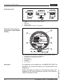
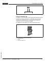
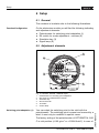
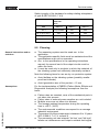
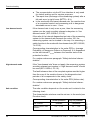
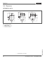
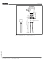
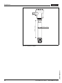
Operating Instructions
OPTISWITCH 3100 C
with NAMUR output
Contents
Contents
1
About this document
1.1
1.2
1.3
2
.
.
.
.
.
.
.
.
.
.
.
.
.
.
.
.
.
.
.
.
.
.
.
.
.
.
.
.
.
.
.
.
.
.
.
.
.
.
.
.
.
.
..
..
..
..
..
..
..
Configuration. . . . . . .
Principle of operation .
Adjustment . . . . . . . .
Storage and transport
.
.
.
.
.
.
.
.
.
.
.
.
.
.
.
.
.
.
.
.
.
.
.
.
.
.
.
.
.
.
.
.
.
.
.
.
.
.
.
.
.
.
.
.
.
.
.
.
.
.
.
.
.
.
.
.
.
.
.
.
.
.
.
.
.
.
.
.
.. 8
.. 8
.. 9
. . 10
General instructions . . . . . . . . . . . . . . . . . . . . . 11
Mounting information . . . . . . . . . . . . . . . . . . . . 12
Preparing the connection . . . . . . . . . . . . . . . . . 15
Connection procedure . . . . . . . . . . . . . . . . . . . 15
Wiring plans, signal chamber housing . . . . . . . . 16
General. . . . . . . . . . . .
Adjustment elements . .
Function chart . . . . . . .
Recurring function test .
.
.
.
.
.
.
.
.
.
.
.
.
.
.
.
.
.
.
.
.
.
.
.
.
.
.
.
.
.
.
.
.
.
.
.
.
.
.
.
.
.
.
.
.
.
.
.
.
.
.
.
.
.
.
.
.
.
.
.
.
.
.
.
.
..
..
..
..
19
19
20
21
.
.
.
.
.
.
.
.
.
.
.
.
.
.
.
.
.
.
.
.
.
.
.
.
.
.
.
.
.
.
.
.
.
.
.
.
.
.
.
.
.
.
.
.
.
.
.
.
.
.
.
.
..
..
..
..
24
24
25
27
Dismounting steps . . . . . . . . . . . . . . . . . . . . . . 28
OPTISWITCH 3100 C - with NAMUR output
31356-EN-051207
Service . . . . . . . . . . . . . . .
Fault rectification . . . . . . . .
Exchanging the electronics.
Instrument repair . . . . . . . .
Dismounting
8.1
2
.
.
.
.
.
.
.
Maintenance and fault rectification
7.1
7.2
7.3
7.4
8
.
.
.
.
.
.
.
Setup
6.1
6.2
6.3
6.4
7
.
.
.
.
.
.
.
Connecting to power supply
5.1
5.2
5.3
6
6
6
6
6
6
7
7
.
.
.
.
.
.
.
Mounting
4.1
4.2
5
Authorised personnel . . . . . . . .
Appropriate use. . . . . . . . . . . .
Warning about misuse . . . . . . .
General safety instructions . . . .
CE conformity . . . . . . . . . . . . .
SIL conformity . . . . . . . . . . . . .
Safety information for Ex areas.
Product description
3.1
3.2
3.3
3.4
4
5
5
5
For your safety
2.1
2.2
2.3
2.4
2.5
2.6
2.7
3
Function . . . . . . . . . . . . . . . . . . . . . . . . . . . . .
Target group . . . . . . . . . . . . . . . . . . . . . . . . . .
Symbolism used . . . . . . . . . . . . . . . . . . . . . . .
Contents
8.2
9
Disposal . . . . . . . . . . . . . . . . . . . . . . . . . . . . . 28
Functional safety
9.1
9.2
9.3
9.4
9.5
9.6
General. . . . . . . . . . . . . . . . . . . . . . . . . . . . . .
Planning . . . . . . . . . . . . . . . . . . . . . . . . . . . . .
Setup . . . . . . . . . . . . . . . . . . . . . . . . . . . . . . .
Reaction during operation and in case of failure.
Recurring function test . . . . . . . . . . . . . . . . . . .
Safety-related characteristics . . . . . . . . . . . . . .
29
30
32
33
33
34
10 Supplement
10.1 Technical data. . . . . . . . . . . . . . . . . . . . . . . . . 37
10.2 Dimensions . . . . . . . . . . . . . . . . . . . . . . . . . . . 41
10.3 Certificates . . . . . . . . . . . . . . . . . . . . . . . . . . . 44
Supplementary operating instructions manuals
Information:
OPTISWITCH 3100 C is available in different versions.
Depending on the selected version, supplementary operating
instructions manuals will also be included in the scope of
delivery. The supplementary operating instructions manuals
are listed in section "Product description".
31356-EN-051207
Operating instructions manuals for accessories and
replacement parts
Tip:
We offer accessories and replacement parts to enable reliable
use and operation of your OPTISWITCH 3100 C. The
corresponding operating instructions manuals are:
l
Operating instructions manual "Oscillator"
OPTISWITCH 3100 C - with NAMUR output
3
About this document
1 About this document
1.1 Function
This operating instructions manual has all the information you
need for quick setup and safe operation of OPTISWITCH 3100
C. Please read this manual before you start setup.
1.2 Target group
This operating instructions manual is directed to trained
personnel. The contents of this manual should be made
available to these personnel and put into practice by them.
1.3 Symbolism used
Information, tip, note
This symbol indicates helpful additional information.
Caution, warning, danger
This symbol informs you of a dangerous situation that could
occur. Ignoring this cautionary note can impair the person and/
or the instrument.
Ex applications
This symbol indicates special instructions for Ex applications.
l
List
The dot set in front indicates a list with no implied sequence.
à
Action
This arrow indicates a single action.
1
Sequence
Numbers set in front indicate successive steps in a procedure.
31356-EN-051207
4
OPTISWITCH 3100 C - with NAMUR output
For your safety
2 For your safety
2.1 Authorised personnel
All operations described in this operating instructions manual
must be carried out only by trained and specialist personnel
authorised by the operator. For safety and warranty reasons,
any internal work on the instruments must be carried out only
by personnel authorised by the manufacturer.
2.2 Appropriate use
OPTISWITCH 3100 C is a sensor for level detection.
Detailed information on the application range of OPTISWITCH
3100 C is available in chapter "Product description".
2.3 Warning about misuse
Inappropriate or incorrect use of the instrument can give rise to
application-specific hazards, e.g. vessel overfill or damage to
system components through incorrect mounting or adjustment.
2.4 General safety instructions
OPTISWITCH 3100 C is a high-tech instrument requiring the
strict observance of standard regulations and guidelines. The
user must take note of the safety instructions in this operating
instructions manual, the country-specific installation standards
(e.g. the VDE regulations in Germany) as well as all prevailing
safety regulations and accident prevention rules.
2.5 CE conformity
OPTISWITCH 3100 C is in CE conformity with EMC (89/336/
EWG), fulfils the NAMUR recommendation NE 21 and is in CE
conformity with NSR (73/23/EWG).
31356-EN-051207
Conformity has been judged acc. to the following standards:
l
EMC:
- Emission EN 61326: 1997 (class B)
- Susceptibility EN 61326: 1997/A1: 1998
l
LVD: EN 61010-1: 2001
OPTISWITCH 3100 C - with NAMUR output
5
For your safety
2.6 SIL conformity
OPTISWITCH 3100 C fulfills the requirements for functional
safety acc. to IEC 61508. You will find further information in
chapter "Functional safety".
2.7 Safety information for Ex areas
Please note the Ex-specific safety information for installation
and operation in Ex areas. These safety instructions are part of
the operating instructions manual and come with the Exapproved instruments.
31356-EN-051207
6
OPTISWITCH 3100 C - with NAMUR output
Product description
3 Product description
3.1 Configuration
Scope of delivery
The scope of delivery encompasses:
l
l
Components
OPTISWITCH 3100 C level sensor
Documentation
- this operating instructions manual
- Supplementary instructions manual "Plug connector for
level sensors" - optional
- Ex specific safety instructions (with Ex versions), if
necessary further certificates
OPTISWITCH 3100 C consists of the following components:
l
l
l
Housing cover
Housing with electronics
process fitting with tuning fork
1
2
3
Fig.
1
2
3
1: OPTISWITCH 3100 C - with plastic housing
Housing cover
Housing with electronics
Process fitting
3.2 Principle of operation
Area of application
OPTISWITCH 3100 C is a level sensor with tuning fork for level
detection.
31356-EN-051207
It is designed for industrial use in all areas of process
technology and is preferably used for bulk solids.
Typical applications are overfill and dry run protection. Thanks
to its simple and robust measuring system, OPTISWITCH
3100 C is virtually unaffected by the chemical and physical
properties of the solid.
OPTISWITCH 3100 C - with NAMUR output
7
Product description
It functions even when exposed to strong external vibration or
changing products.
Solid detection in water
If OPTISWITCH 3100 C was ordered for solid detection in
water, the tuning fork is set to the density of water. In air or if
immersed in water (density: 1 g/cm³ / 0.036 lbs/in), OPTISWITCH 3100 C signals uncovered. Only if the vibrating
element is also covered with solids (e.g. sand, sludge, gravel
etc.) will the sensor signal covered.
Fault monitoring
The electronics of OPTISWITCH 3100 C continuously monitors the following criteria:
l
l
Correct vibrating frequency
Line break to the piezo drive
If one of these faults is detected, the electronics signals it via a
defined current to the signal conditioning instrument. The
connection cable to the vibrating element is also monitored.
Physical principle
The tuning fork is piezoelectrically energised and vibrates at its
mechanical resonance frequency of approx. 150 Hz. When the
tuning fork is submerged in the product, the vibrating
amplitude changes. This change is detected by the integrated
oscillator and converted into a switching command.
Power supply
OPTISWITCH 3100 C with NAMUR electronics can be
connected to different NAMUR amplifiers depending to your
requirements. The specifications for NAMUR amplifiers are
available in the Technical data.
The exact range of the power supply is stated in the Technical
data in the Supplement.
3.3 Adjustment
With the factory setting, products with a density of >0.02 g/cm³
(>0.0008 lbs/in³) can be measured. It is possible to adapt the
instrument for products with lower density >0.008 g/cm³
(>0.0003 lbs/in³).
On the electronics module you will find the following indicating
and adjustment elements:
l
l
8
signal lamp for indication of the switching condition (yellow)
potentiometer for adaptation to the product density
Mode switch to select the switching condition (reverse
characteristics)
OPTISWITCH 3100 C - with NAMUR output
31356-EN-051207
l
Product description
l
Simulation key
3.4 Storage and transport
Packaging
Your instrument was protected by packaging during transport.
Its capacity to handle normal loads during transport is assured
by a test acc. to DIN 55439.
The packaging of standard instruments consists of environment-friendly, recyclable cardboard. In addition, the sensor is
provided with a protective cover of cardboard. For special
versions PE foam or PE foil is also used. Dispose of the
packaging material via specialised recycling companies.
Storage and transport temperature
l
31356-EN-051207
l
Storage and transport temperature see "Supplement Technical data - Ambient conditions"
Relative humidity 20 … 85 %
OPTISWITCH 3100 C - with NAMUR output
9
Mounting
4 Mounting
4.1 General instructions
Switching point
In general, OPTISWITCH 3100 C can be mounted in any
position. The instrument must be mounted in such a way that
the tuning fork is at the height of the requested switching point.
Moisture
Use the recommended cable (see chapter "Connecting to
power supply") and tighten the cable gland.
You can give your OPTISWITCH 3100 C additional protection
against moisture penetration by leading the connection cable
downward in front of the cable entry. Rain and condensation
water can thus drain off. This applies mainly to mounting
outdoors, in areas where moisture is expected (e.g. by
cleaning processes) or on cooled or heated vessels.
Fig. 2: Measures against moisture penetration
Transport
Do not hold OPTISWITCH 3100 C on the vibrating element.
Especially with flange and tube versions, the sensor can be
damaged by the weight of the instrument.
Remove the protective cover just before mounting.
The process fitting must be sealed if there is gauge or low
pressure in the vessel. Before use, check if the seal material is
resistant against the measured product and the process
temperature.
Handling
The vibrating level switch is a measuring instrument and must
be treated accordingly. Bending the vibrating element will
destroy the instrument.
10
OPTISWITCH 3100 C - with NAMUR output
31356-EN-051207
Pressure/Vacuum
Mounting
Warning:
The housing must not be used for screwing in! Tightening can
cause damages on the locking piston of the housing.
To screw in, use the hexagon above the thread.
4.2 Mounting information
Socket
The vibrating element should protrude into the vessel to avoid
buildup. For that reason, avoid using mounting bosses for
flanges and screwed fittings. This applies particularly to use
with adhesive products.
Filling opening
Install the instrument in such a way that the tuning fork does
not protrude directly into the filling stream. Should such an
installation location be necessary, mount a suitable baffle
above or in front of the tuning fork.
If such an installation location should be necessary, mount a
suitable protective sheet above or in front of the vibrating
element - see illustration a.).
In abrasive solids, mounting acc. to illustration b. has proven. A
spout forms in the concave protective sheet preventing wear of
the protective sheet.
To achieve a very precise switching point, you can install
OPTISWITCH 3100 C horizontally. However, if the switching
point can have a tolerance of a few centimeters, we
recommend mounting OPTISWITCH 3100 C approx. 20°
inclined to the vessel bottom to avoid buildup.
31356-EN-051207
Horizontal installation
OPTISWITCH 3100 C - with NAMUR output
11
Mounting
a.
b.
20°
Fig. 3: Horizontal installation
a Protective sheet
b Concave protective sheet for abrasive solids
Inflowing material
If OPTISWITCH 3100 C is mounted in the filling stream,
unwanted switching signals may be generated. Mount OPTISWITCH 3100 C at a location in the vessel where no disturbing
influence from e.g. filling openings, agitators, etc. can occur.
Flow
If there is movement within the product, the tuning fork of
OPTISWITCH 3100 C should be mounted in such a way that
the surfaces of the fork are parallel to the product movement.
1
2
12
OPTISWITCH 3100 C - with NAMUR output
31356-EN-051207
Fig. 4: Orientation of the tuning fork in case of flow
1 Marking with screwed version
2 Direction of flow
Mounting
Adhesive products
In case of horizontal mounting in adhesive products, the
surfaces of the tuning fork should be vertical in order to reduce
buildup on the tuning fork. On the screwed version you will find
a marking on the hexagon. With this, you can check the
position of the tuning fork when screwing it in. When the
hexagon touches the seal, the thread can be still turned by
approx. half a turn. This is sufficient to reach the recommended installation position.
With flange versions, the fork is directed to the flange holes.
1
Fig. 5: Vertical installation - marking
1 Marking on top with screwed version
Baffle protection against falling rocks
In applications such as grit chambers or settling basins for
coarse sediments, the vibrating element must be protected
against damage with a suitable baffle.
31356-EN-051207
>150
Fig. 6: Baffle protection against damages
OPTISWITCH 3100 C - with NAMUR output
13
Connecting to power supply
5 Connecting to power supply
5.1 Preparing the connection
Note safety instructions
Always observe the following safety instructions:
l
Connect only in the complete absence of line voltage
Take note of safety
instructions for Ex
applications
In hazardous areas you should take note of the appropriate
regulations, conformity and type approval certificates of the
sensors and power supply units.
Select power supply
Connect the power supply acc. to the following diagrams. Take
note of the general installation regulations. As a rule, connect
OPTISWITCH 3100 C to vessel ground (PA), or in case of
plastic vessels, to the next ground potential. On the side of the
instrument housing there is a ground terminal between the
cable entries. This connection serves to drain off electrostatic
charges. In Ex applications, the installation regulations for
hazardous areas must be given priority.
The data for power supply are stated in the Technical data in
the Supplement.
Select connection cable
OPTISWITCH 3100 C is connected with standard cable with
round cross-section. An outer cable diameter of 5 ... 9 mm
(0.2 ... 0.35 in) ensures the seal effect of the cable entry.
If cable with a different diameter or wire cross section is used,
exchange the seal or use an appropriate cable connection.
In hazardous areas, only use approved cable connections for
OPTISWITCH 3100 C.
Select connection
cable for Ex applications
Take note of the corresponding installation regulations for Ex
applications.
5.2 Connection procedure
With Ex instruments, the housing cover may only be opened if
there is no explosive atmosphere present.
14
1
Unscrew the housing cover
2
Loosen compression nut of the cable entry
OPTISWITCH 3100 C - with NAMUR output
31356-EN-051207
Proceed as follows:
Connecting to power supply
3
Remove approx. 10 cm (4 in) of the cable mantle, strip
approx. 1 cm (0.4 in) insulation from the ends of the
individual wires
4
Insert the cable into the sensor through the cable entry
5
Lift the opening levers of the terminals with a screwdriver
(see following illustration)
6
Insert the wire ends into the open terminals according to
the wiring plan
7
Press down the opening levers of the terminals, you will
hear the terminal spring closing
8
Check the hold of the wires in the terminals by lightly
pulling on them
9
Tighten the compression nut of the cable entry, the seal
ring must completely encircle the cable
10 Screw the housing cover back on
The electrical connection is finished.
Fig. 7: Connection steps 5 and 6
31356-EN-051207
5.3 Wiring plans, signal chamber housing
The following illustrations apply to the non-Ex as well as to the
EEx d version.
OPTISWITCH 3100 C - with NAMUR output
15
Connecting to power supply
Housing overview
4
4
1
Fig.
1
2
3
4
Electronics and connection
compartment, single chamber
housing
4
2
3
8: Material versions, single chamber housing
Plastic
Aluminium
Stainless steel
Filter element for pressure compensation
1
6
VB60N
NAMUR IEC 60947-5-6
2
Simulation
5
3
4
Fig.
1
2
3
4
5
6
Wiring plan
9: Electronics and connection compartment, single chamber housing
Potentiometer for switching point adaptation
DIL switch for characteristics reversal
Simulation key
Ground terminal
Terminals
Control lamp
For connection to an amplifier acc. to NAMUR (IEC 60947-5-6,
EN 50227). For further information see Technical data in the
Supplement.
16
OPTISWITCH 3100 C - with NAMUR output
31356-EN-051207
Further information you will find in the Technical data in the
Supplement, Ex technical data are specified in the attached
safety instructions manual.
Connecting to power supply
- +
1 2
+
-
Fig. 10: Wiring plan, single chamber housing
External simulation key
In addition to the test key on the electronics module, you can
connect an external modulator to start the test procedure.
Connect the modulator acc. to the following wiring plan.
Terminals 3 and 4 are already bridged.
For additional information see "Recurring function test".
+ -
1 2 3 4
+
-
3
11: Wiring plan - External simulation key
NAMUR amplifier
Bridge
External simulation key
31356-EN-051207
Fig.
1
2
3
1
2
OPTISWITCH 3100 C - with NAMUR output
17
Setup
6 Setup
6.1 General
The numbers in brackets refer to the following illustrations.
Function/Configuration
On the electronics module you will find the following indicating
and adjustment elements:
l
l
l
l
Potentiometer for switching point adaptation (1)
DIL switch for mode adjustment - min/max (2)
Simulation key (3)
Signal lamp (6)
6.2 Adjustment elements
1
6
VB60N
NAMUR IEC 60947-5-6
2
Simulation
5
3
4
Fig.
1
2
3
4
5
6
Switching point adaptation (1)
12: Oscillator VB 60N - NAMUR output
Potentiometer for switching point adaptation
DIL switch for characteristics reversal
Simulation key
Ground terminal
Terminals
Control lamp
The factory setting of the potentiometer of OPTISWITCH 3100
C is mid position (>0.02 g/cm³ or >0.0008 lbs/in³). In case of
18
OPTISWITCH 3100 C - with NAMUR output
31356-EN-051207
You can adapt the switching point to the solid with the
potentiometer. The switching point is preset and covered by a
label. It must only be modified in special cases.
Setup
very light solids, turn the potentiometer completely to the left
(>0.008 g/cm³ or >0.0003 lbs/in³). By doing this, OPTISWITCH
3100 C will be more sensitive and light solids can be detected
more reliably.
For instruments detecting solids in water, these values are not
applicable. The potentiometer is preset and must not be
changed.
Characteristics reversal (2)
The characteristics reversal can be carried out with the DIL
switch. You can choose between falling characteristics (switch
position max.) and rising characteristics (switch position min.).
You can have the requested current outputted.
Modes
l
l
min. - rising characteristic curve (High current when
immersed)
max. - falling characteristics (Low current when immersed)
The NAMUR output can be switched over to falling or rising
characteristics (see also Function chart).
Simulation key (3)
The simulation key is located in a recess on the upper side of
the oscillator. Push the simulation key with a suitable object
(screwdriver, pen, etc.).
When the key is pushed, line break between sensor and
processing unit is simulated. The signal lamp on the sensor
extinguishes. The measuring system must signal failure and
take on safe condition when the key is pushed.
Keep in mind that the connected instruments are activated
during operation. By doing this, you can check the correct
function of the measuring system.
Signal lamp (6)
Control lamp (LED) for indication of the switching condition.
l
l
l
yellow = High current >= 2.2 mA
dark = Low current <= 1 mA
yellow (flashing) = Failure <= 1 mA
31356-EN-051207
6.3 Function chart
OPTISWITCH 3100 C level switch
The following chart provides an overview of the switching
conditions depending on the adjusted mode and level.
OPTISWITCH 3100 C - with NAMUR output
19
Setup
Note:
Select the mode setting on the NAMUR amplifier in such a way
that the switching output takes on safe condition if there is a
fault signal (I <= 1.0 mA).
Level
Signal current Sensor
Falling characteristics max.
>= 2.2 mA
Falling characteristics max.
<= 1.0 mA
Rising characteristics min.
>= 2.2 mA
Rising characteristics min.
<= 1.0 mA
Failure
any
Control lamp
<= 1.0 mA
flashes
6.4 Recurring function test
Acc. to IEC 61508.
In mode A (overfill protection), OPTISWITCH 3100 C is
qualified for use in measuring chains of stage SIL2 acc. to IEC
61508 (redundant, stage SIL3).
SIL
The following instrument combinations meet the requirements
acc. to SIL:
OPTISWITCH 3100 C
20
Oscillator VB E60N
OPTISWITCH 3100 C - with NAMUR output
31356-EN-051207
l
Setup
Recurring function test
The recurring function test acc. to IEC 61508 can be carried
out by pushing the simulation key on the electronics module or
by briefly (> 2 seconds) interrupting the cable to the sensor.
The correct sequence of the switching conditions must be
monitored on the switch amplifier as well as on the connected
systems. Neither must the sensor be removed nor a response
triggered by filling the vessel. This applies to OPTISWITCH
3100 C with NAMUR oscillator VB E60N.
You can carry out the function test with the outputted current
values also directly with a safety PLC or a process control
system.
Simulation key on the electronics module
In applications in conjunction with the NAMUR electronics
module VB E60N, a function test can be carried out. Hence the
integration time must be set to 0.5 s. OPTISWITCH 3100 C
has an integrated simulation key. The simulation key is
lowered on the electronics module. Push the simulation key for
> 2 seconds.
If OPTISWITCH 3100 C is connected to an SPLC, you have to
interrupt the connection cable to the sensor for > 2 seconds.
After releasing the simulation key or briefly interrupting the
connection cable to the sensor, you can check the complete
measuring system on correct function. A switching procedure
is simulated during the test.
I/mA
2,2
1
1
2
3
4,5
t/s
31356-EN-051207
Fig. 13: Flow chart of the function test
1 Full signal
2 Empty signal
Check if the switching conditions occur in the correct
sequence and the stated time period. If this is not the case,
there is a fault in the measuring system. Keep in mind that
OPTISWITCH 3100 C - with NAMUR output
21
Setup
connected instruments are activated during the function test.
By doing this, you can check the correct function of the
measuring system.
Test procedure
(after releasing the simulation key)
Sensor cur- Level relay
rent
amplifier overfill protection
Level relay
amplifier dry run
protection
1. Low Current
(approx. 3 s)
approx. 1
mA
energized
currentless
2. High Current
(approx. 1.5 s)
approx. 2.2
mA
currentless
energized
Signal lamp
amplifier overfill protection
Signal lamp
amplifier dry run
protection
Signal
lamp sensor
3. Return to the actual operating condition
Note:
Mode B (dry run protection) is not permitted, when used in
meas. chains acc. to IEC 61508.
With the stated current values you can carry out the function
test directly via a safety PLC or a process control system.
31356-EN-051207
22
OPTISWITCH 3100 C - with NAMUR output
Maintenance and fault rectification
7 Maintenance and fault rectification
7.1 Service
When used as directed in normal operation, OPTISWITCH
3100 C is completely maintenance-free.
7.2 Fault rectification
OPTISWITCH 3100 C offers maximum reliability. Nevertheless
faults can occur during operation. These may be caused by the
following, e.g.:
l
l
l
l
Fault rectification
Sensor
Process
Power supply
Signal processing.
The first measure to be taken is to check the output signal. In
many cases, the causes can be determined and faults
rectified.
?
OPTISWITCH 3100 C signals "covered" when the vibrating
element is not submerged (overfill protection)
?
OPTISWITCH 3100 C signals "uncovered" when the
vibrating element is submerged (dry run protection)
l Supply voltage too low
à Check the power supply
l Electronics defective
à Push the characteristics reversal switch. If the instru-
ment then changes the mode, the instrument may be
mechanically damaged. Should the switching function
in the correct mode still be faulty, return the instrument
for repair.
à Push the characteristics reversal switch. If the instrument then does not change the mode, the oscillator
may be defective. Exchange the oscillator.
à Check if there is buildup on the vibrating element, and if
31356-EN-051207
so, remove it.
l Unfavourable installation location
à Mount the instrument at a location where no dead
zones or mounds can form in the vessel.
OPTISWITCH 3100 C - with NAMUR output
23
Maintenance and fault rectification
à Check if the vibrating element is covered by buildup on
the socket.
l Wrong characteristics selected
à Set the correct characteristics on the characteristics
reversal switch (overfill protection; dry run protection).
Wiring should be carried out acc. to the quiescent
current principle.
?
Signal lamp flashes yellow
l Failure on the electronics
à Exchanging the electronics
?
Signal lamp flashes yellow
l instrument defective
à Exchange instrument or return it for repair
7.3 Exchanging the electronics
In general, all oscillators of series VB60 can be interchanged. If
you want to use an oscillator with a different signal output, you
can download the corresponding operating instructions manual from our homepage under Downloads.
With EExd instruments, the housing cover must only be
opened if there is no explosive atmosphere present.
Proceed as follows:
1
Switch off power supply
2
Unscrew the housing cover
3
Lift the opening levers of the terminals with a screwdriver
4
Pull the connection cables out of the terminals
5
Loosen the two screws with a Phillips screwdriver (size 1)
31356-EN-051207
24
OPTISWITCH 3100 C - with NAMUR output
Maintenance and fault rectification
1
2
Fig. 14: Loosen the screws
1 Electronics module
2 Screws (2 pcs.)
6
Remove the old oscillator
7
Compare the new oscillator with the old one. The type label
of the oscillator must correspond to that of the old
oscillator. This applies particularly to instruments used in
hazardous areas.
8
Compare the settings of the two oscillators. Set the
adjustment elements of the new oscillator to the settings of
the old oscillator.
Information:
Make sure that the housing is not rotated during the electronics
exchange. Otherwise the plug may be in a different position
later.
9
Insert the oscillator carefully. Make sure that the plug is in
the correct position.
10 Screw in and tighten the two screws with a Phillips
screwdriver.
11 Insert the wire ends into the open terminals according to
the wiring plan
31356-EN-051207
12 Close the opening levers of the terminals, you will hear the
terminal spring closing
13 Check the hold of the wires in the terminals by lightly
pulling on them
14 Check the tightness of the cable entry. The seal ring must
completely encircle the cable.
15 Screw the housing cover back on
OPTISWITCH 3100 C - with NAMUR output
25
Maintenance and fault rectification
The electronics exchange is finished.
7.4 Instrument repair
If a repair is necessary, please proceed as follows:
You can download a return form from our Internet homepage
http://www.krohne-mar.com/fileadmin/media-lounge/PDFDownload/Specimen_e.pdf.
By doing this you help us carry out the repair quickly and
without having to call back for needed information.
l
l
l
Print and fill out one form per instrument
Clean the instrument and pack it damage-proof
Attach the completed form and possibly also a safety data
sheet to the instrument
31356-EN-051207
26
OPTISWITCH 3100 C - with NAMUR output
Dismounting
8 Dismounting
8.1 Dismounting steps
Warning:
Before dismounting, be aware of dangerous process conditions such as e.g. pressure in the vessel, high temperatures,
corrosive or toxic products etc.
Take note of chapters "Mounting" and "Connecting to power
supply" and carry out the listed steps in reverse order.
With Ex instruments, the housing cover may only be opened if
there is no explosive atmosphere present.
8.2 Disposal
OPTISWITCH 3100 C consists of materials which can
recycled by specialised recycling companies. We have
purposely designed the electronic modules to be easily
separable.
WEEE directive 2002/96/EG
This instrument is not subject to the WEEE directive 2002/96/
EG and the respective national laws (in Germany, e.g.
ElektroG). Pass the instrument directly on to a specialised
recycling company or use the municipal collecting points. They
may only be used for privately used products acc. to the
WEEE directive.
Correct disposal avoids negative effects to persons and
environment and ensures recycling of useful raw materials.
Materials: see "Technical data"
31356-EN-051207
If you cannot dispose of the instrument properly, please
contact us about disposal methods or return.
OPTISWITCH 3100 C - with NAMUR output
27
Functional safety
9 Functional safety
9.1 General
Validity
This safety manual applies to measuring systems consisting of
OPTISWITCH 3100 C vibrating level switches and integrated
oscillator VB60N. The instrument corresponds to a subsystem
of type B.
The sensor software must correspond at least to version 1.00
or higher.
Area of application
The measuring system can be used for level detection of
powders and granules which meet the specific requirements of
the safety technology, e.g.:
l
l
Mode "max" for overfill protection
Mode "min" for dry run protection
The measuring system is qualified in both modes to meet the
following requirement degree acc. to IEC 61508-2:
l
l
SIL2 with architecture 1oo1D (single channel)
SIL3 with architecture 1oo2D (double-channel/redundant)
With a special factory setting, the measuring system is also
suitable for detection of solids in water (see operating
instructions manual).
Safety function
The safety function of this measuring system is the detection
and signalling of the condition of the vibration element. The
safe condition depends on the mode:
l
l
In mode "max": condition "covered"
In mode "min": condition "uncovered"
IEC 61508-1, -2, -4
- Functional safety of electrical/electronic/programmable
electronic systems
Relevant standards
l
Safety requirements
The failure limit values for a safety function, depending on the
SIL class (of IEC 61508-1, 7.6.2)
Safety integrity level
High demand mode
PFDavg
PFH
4
>=10-5 up to <10-4
>=10-9 up to <10-8
3
>=10-4 up to <10-3
>=10-8 up to <10-7
2
>=10-3 up to <10-2
>=10-7 up to <10-6
-2
>=10 up to <10
-1
>=10-6 up to <10-5
OPTISWITCH 3100 C - with NAMUR output
31356-EN-051207
SIL
1
28
Low demand mode
Functional safety
Safety integrity of the hardware for safety-relating subsystems
of type B (IEC 61508-2, 7.4.3)
Safe failure fraction
Hardware
fault tolerance
SFF
HFT = 0
HFT = 1
HFT = 2
<60 %
not permitted
SIL1
SIL2
60 % up to <90 %
SIL1
SIL2
SIL3
90 % up to <99 %
SIL2
SIL3
(SIL4)
>=99 %
SIL3
(SIL4)
(SIL4)
9.2 Planning
General instructions and restrictions
l
l
l
l
The measuring system must be used acc. to the
application
The application-specific limits must be maintained and the
specifications must not be exceeded.
Acc. to the specifications in the operating instructions
manual, the current load of the output circuits must be
within the limits.
It must be used only in products to which the materials of
the vibrating system are sufficiently chemically resistant.
Note the following items for use as dry run protection system:
l
l
Assumptions
For the implementation of FMEDA (Failure Mode, Effects and
Diagnostics Analysis) the following assumptions form the
basis:
l
l
l
l
l
31356-EN-051207
Avoid buildup on the vibrating system (possibly smaller
proof test intervals)
Avoid granulation size of the product > 15 mm
l
l
Failure rates are constant, wear of the mechanical parts is
not taken into account
Failure rates of external power supplies are not included
Multiple errors are not taken into account
The average ambient temperature during the operating
time is +40°C (104°F)
The environmental conditions correspond to an average
industrial environment
The service lift of the components is between 8 to 12 years
(IEC 61508-2, 7.4.7.4, remark 3)
The processing unit can interpret "fail low" and "fail high"
failures as interferences and output a suitable fault signal
OPTISWITCH 3100 C - with NAMUR output
29
Functional safety
l
l
l
Low demand mode
The communication via the IIC bus interface is only used
for default scaling and for service purposes.
The repair time (exchange of the measuring system) after a
fail-safe error is eight hours (MTTR = 8 h)
In the mode with the lowest demand rate, the reaction time
of a connected control and processing unit to dangerous
detectable errors is max. 1 hour.
If the demand rate is only once a year, then the measuring
system can be used as safety-relevant subsystem in "low
demand mode" (IEC 61508-4, 3.5.12).
If the ratio of the internal diagnostics test rate of the measuring
system to the demand rate exceeds the value 100, the
measuring system can be treated in the way it is executing a
safety function in the mode with low demand rate (IEC 61508-2,
7.4.3.2.5).
Corresponding characteristics is the value PFDavg (average
Probability of dangerous Failure on Demand). It is dependent
on the test interval TProof between the function tests of the
protective function.
For number values see paragraph "Safety-technical characteristics".
High demand mode
If the "low demand rate" does not apply, the measuring system
as safety-relevant part system in "high demand mode" should
be used (IEC 61508-4, 3.5.12).
The fault tolerance time of the complete system must be higher
than the sum of the reaction times or the diagnostics test
periods of all components in the safety chain.
Corresponding characteristics is the value PFH (failure rate).
For number values see paragraph "Safety-technical characteristics".
Safe condition
The safe condition depends on the mode and is stated in the
following chart:
The characteristics min/max must be set acc. to the mode (see
Function chart).
30
Dry run protection
"covered"
"uncovered"
0.4 … 1 mA
0.4 … 1 mA
OPTISWITCH 3100 C - with NAMUR output
31356-EN-051207
Safe condition
Output current in safe
condition
Overfill protection
Functional safety
Fault description
Overfill protection
Dry run protection
Interference current "Fail
Low"
< 1 mA
< 1 mA
Interference current "Fail
High"
> 6.5 mA
> 6.5 mA
A safe failure exists if the measuring system goes to the
defined safe condition without being required by the process or
the interference current outputs "Fail low" or "Fail high".
If the internal diagnostics system detects an error, an
interference current of < 1 mA will be outputted.
A dangerous undetected failure exists if the measuring system
switches neither to the defined safe condition, nor to failure
mode when the process requires it.
Configuration of the processing unit
If the measuring system delivers output currents of "fail low" or
"fail high", it can be assumed that there is a failure somewhere.
The processing unit must therefore interpret such currents as
failure and output a suitable fault signal.
If this is not the case, the appropriate shares of the failure rates
must be assigned to the dangerous failures. Therefore the
stated values in chapter "Safety-relevant characteristics" can
deteriorate.
The processing unit must correspond to the SIL level of the
measuring chain.
The adjustment of the mode on the NAMUR amplifier acc. to
IEC 60947-5-6 must be selected in such a way that its
switching condition takes on safe condition if there is an input
current < 1.2 mA.
9.3 Setup
The prevailing plant conditions influence the safety of the
measuring system. Therefore note the mounting and installation instructions of the appropriate operating instructions
manual. Mainly important is the correct setting of the mode
(min./max.).
31356-EN-051207
Mounting and installation
OPTISWITCH 3100 C - with NAMUR output
31
Functional safety
9.4 Reaction during operation and in case of
failure
l
l
l
l
l
l
The adjustment elements must not be modified during
operation.
In case of modifications during operation, you have to take
note of the safety functions.
Occurring fault signals are described in the appropriate
operating instructions manual.
In case of detected failures or fault signals, the entire
measuring system must be switched out of service and the
process held in a safe condition by means of other
measures.
An electronics exchange is easily possible and described
in the operating instructions manual.
If due to the detected failure, the electronics or the
complete sensor is interchanged, the manufacturer must
be informed (incl. a fault description).
9.5 Recurring function test
The recurring function test serves to reveal potential dangerous errors that are otherwise not discernible. The function of
the measuring system must be checked at adequate intervals.
The operator is responsible for choosing the type of test and
the intervals in the stated time frame. The time frame depends
on the PFDavg value acc. to the chart and diagram in section
"Safety-related characteristics".
In high demand rate, no recurring function test is arranged in
IEC 61508. A proof of the functional efficiency is seen in the
more frequent demand of the measuring system. In double
channel architectures it is useful to proof the redundancy by
recurring function tests in appropriate intervals.
The test must be carried out in a way that verifies the flawless
operation of the safety functions in conjunction with all system
components.
This is ensured by a controlled reaching of the response height
during filling. If filling up to the response height is not possible,
then a response of the measuring system must be triggered by
a suitable simulation of the level or the physical effect.
32
OPTISWITCH 3100 C - with NAMUR output
31356-EN-051207
The methods and procedures used during the tests must be
stated and their suitability must be specified. The tests must be
documented.
Functional safety
If the function test proves negative, the entire measuring
system must be switched out of service and the process held
in a safe condition by means of other measures.
In the double channel architecture 1oo2D this applies
separately to both channels.
Recurring function test when
using the measuring system
as overfill protection
If the measuring system is used as overfill protection, the proof
of the function is ensured by a simple function test which can
be triggered and monitored manually or by a connected control
system.
This function test is triggered by interrupting the supply cable
for at least two seconds, then a switch on procedure follows as
described in the operating instructions manual.
If the test is carried out this way, make sure that the vibrating
element is not covered.
If the evaluation is made by a control system, the correct
sequence of the current change must be checked and
documented.
9.6 Safety-related characteristics
The failure rates of the electronics and the vibrating system
were determined by an FMEDA acc. to IEC 61508. Basis for
the calculations are component failure rates acc. to SN 29500.
All values relate to an average ambient temperature of +40°C
(104°F) during operation. The calculations are further based
on the instructions stated in chapter "Planning".
Mode switch is set to "max"
λsd
12 FIT
safe detected failure (1 FIT = failure/109h)
λsu
160 FIT
safe undetected failure
λdd
390 FIT
dangerous detected failure
λdu
47 FIT
dangerous undetected failure
SFF
> 92 %
Safe Failure Fraction
DCS
7%
Diagnosis coverage DCS = λsd/(λsd + λsu)
DCD
89 %
Diagnosis coverage DCD = λdd/(λdd + λdu)
31356-EN-051207
Overfill protection
OPTISWITCH 3100 C - with NAMUR output
33
Functional safety
Dry run protection
Mode switch is set to "min"
λsd
36 FIT
safe detected failure
λsu
155 FIT
safe undetected failure
λdd
366 FIT
dangerous detected failure
λdu
52 FIT
dangerous undetected failure
Safe Failure Fraction
SFF
> 91 %
DCS
19 %
Diagnosis coverage DCS = λsd/(λsd + λsu)
DCD
88 %
Diagnosis coverage DCD = λdd/(λdd + λdu)
General data
TDiagnosis Diagnosis test period
100 sec
1.56x10⁶ h
MTBF = MTTF + MTTR
max. useful life of the measuring system for the safety
function
Architecture 1oo1D - Overfill
protection
approx. 10 years
Single channel architecture
SIL2 (Safety Integrity Level)
HFT = 0 (Hardware Fault Tolerance)
Mode switch is set to "max"
PFDavg
TProof = 1 year
TProof = 5 years
TProof = 10 years
< 0.020 x 10⁻²
< 0.100 x 10⁻²
< 0.200 x 10⁻²
< 0.047 x 10⁻⁶/h
PFH [1/h]
Architecture 1oo1D - Dry run
protection
SIL2 (Safety Integrity Level)
HFT = 0 (Hardware Fault Tolerance)
Mode switch is set to "min"
PFDavg
TProof = 1 year
TProof = 5 years
TProof = 10 years
34
< 0.052 x 10⁻⁶/h
OPTISWITCH 3100 C - with NAMUR output
31356-EN-051207
PFH [1/h]
< 0.023 x 10⁻²
< 0.114 x 10⁻²
< 0.228 x 10⁻²
Functional safety
Time-dependent process of
PFDavg
The time-dependent process of PFDavg reacts in the time
period up to 10 years virtually linear to the operating time. The
above values only apply to the TProof interval, after which a
recurring function test must be carried out.
4
PFDavg
3
2
1
1
Fig.
1
2
3
4
Architecture 1oo2
5
10
TProof
15: Time-dependent process of PFDavg1)
PFDavg = 0
PFDavg after 1 year
PFDavg after 5 years
PFDavg after 10 years
Multiple channel architecture
SIL3 (Safety Integrity Level)
HFT = 1 (Hardware Fault Tolerance)
SIL
SIL3
HFT
1
If the measuring instrument is used in double channel
architecture, the safety-relevant characteristics of the selected
structure of the measuring chain must be calculated specifically for the selected application acc. to the above failure rates
. A Common Cause Factor must be taken into account.
31356-EN-051207
The measuring system can be used in a diversitary redundant
as well as a homogeneous redundant structure.
1)
Numbers see in the above charts.
OPTISWITCH 3100 C - with NAMUR output
35
Supplement
10 Supplement
10.1 Technical data
General data
Material 316L corresponds to 1.4404 or 1.4435
Materials, wetted parts
- Process fitting - Thread
316L
-
Process fitting - Flange
316L
-
Process seal
Klingersil C-4400
-
Tuning fork
316L
-
Extension tube ø 43 mm (ø 1.7 in)
316L
Materials, non-wetted parts
- Housing
plastic PBT (Polyester), Alu-die casting powder-coated, stainless steel 316L
-
Seal ring between housing and
housing cover
NBR (stainless steel housing), silicone (Alu/
plastic housing)
-
Ground terminal
316L
Weights
- with plastic housing
1500 g (53 oz)
-
with Aluminium housing
1950 g (69 oz)
-
with stainless steel housing
2300 g (81 oz)
Max. lateral load
600 N (135 lbf) longitudinal to the fork side
Output variable
Output
Current consumption
- Falling characteristics (max.)
two-wire NAMUR output
-
Rising characteristics (min.)
<=1.0 mA uncovered/>=2.2 mA covered
-
Fault signal
<=1.0 mA
>=2.2 mA uncovered/<=1.0 mA covered
Necessary processing system
NAMUR processing system acc. to IEC
60947-5-6 (EN 50 227/DIN 19234)
Modes (NAMUR output adjustable to falling or rising characteristics)
- Min.
rising characteristics (High current when immersed)
36
max.
falling characteristics (Low current when immersed)
OPTISWITCH 3100 C - with NAMUR output
31356-EN-051207
-
Supplement
Ambient conditions
Ambient temperature on the housing
Storage and transport temperature
-40 … +80°C (-40 … +176°F)
-40 … +80°C (-40 … +176°F)
Process conditions
Parameter
Process pressure
level of solids
-1 … 16 bar (-100 … 1600 kPa / -14.5 … 232 psi)
2
16 bar
(232psi)
6 bar
(87psi)
-50˚C
(-58˚F)
0˚C
(32˚F)
1
50˚C
(122˚F)
100˚C
(212˚F)
150˚C
(302˚F)
200˚C
(392˚F)
250˚C
(482˚F)
Fig. 16: Process pressure - Product temperature
1 Product temperature
2 Process pressure
OPTISWITCH 3100 C of 316L
Process temperature (thread or flange
temperature) with temperature adapter
(option)
-50 … +150°C (-58 … +302°F)
-50 … +250°C (-58 … +482°F)
2
3
80˚C
(176˚F)
40˚C
(104˚F)
-50˚C
(-58˚F)
0˚C
(32˚F)
1
50˚C
(122˚F)
100˚C
(212˚F)
150˚C
(302˚F)
200˚C
(392˚F)
250˚C
(482˚F)
31356-EN-051207
-40˚C
(-40˚F)
Fig.
1
2
3
17: Ambient temperature - Product temperature
Product temperature
Ambient temperature
Temperature range with temperature adapter
Density
OPTISWITCH 3100 C - with NAMUR output
37
Supplement
-
Standard
>0.02 g/cm³ (>0.0007 lbs/in³)
-
adjustable
>0.008 g/cm³ (>0.0003 lbs/in³)
Electromechanical data
Cable entry/plug2)
- Single chamber housing
l
or:
l
1x cable entry M20x1.5 (cable-ø 5 … 9 mm),
1x blind stopper M20x1.5
1x closing cap ½ NPT, 1x blind stopper
½ NPT
or:
l
Spring-loaded terminals
1x plug (depending on the version), 1x blind
stopper M20x1.5
for wire cross section up to 1.5 mm² (0.0023 in²)
Adjustment elements
Mode switch
- Min.
-
rising characteristics (High current when immersed)
Max.
falling characteristics (Low current when immersed)
Potentiometer for switching point adaptation
Simulation key
0.02 … 0.1 g/cm³ (0.0007 … 0.036 lbs/in³)
simulation of a line break between sensor and
processing unit
Voltage supply
Supply voltage (standard characteristics)
Open-circuit voltage
Short-circuit current
for connection to an amplifier acc. to NAMUR
IEC 60947-5-6, approx. 8.2 V
U0 approx. 8.2 V
IU approx. 8.2 mA
Electrical protective measures
Protection
Overvoltage category
Protection class
IP 66/IP 67
III
II
38
Depending on the version M12x1, acc. to DIN 43650, Harting, AmphenolTuchel, 7/8" FF
OPTISWITCH 3100 C - with NAMUR output
31356-EN-051207
2)
Supplement
Approvals3)
ATEX II 1G, 1/2G, 2G EEx ia IIC T6 + ATEX II 1/2 D IP66 T
ATEX II 1/2G, 2G EEx d IIC T6
31356-EN-051207
ATEX II 1/2 D IP66 T
4)
3)
4)
Deviating data with Ex applications: see separate safety instructions.
See temperature statements in the safety instructions manual
OPTISWITCH 3100 C - with NAMUR output
39
Supplement
10.2 Dimensions
OPTISWITCH 3100 C5)
~ 69mm
(2 23/32")
1
Fig.
1
2
3
2
M20x1,5
3
18: Housing versions
Plastic housing
Stainless steel housing
Aluminium housing
All dimensions in mm (inch).
OPTISWITCH 3100 C - with NAMUR output
31356-EN-051207
5)
40
M20x1,5/
½ NPT
M20x1,5/
½ NPT
½
114mm
(4 31/64")
117mm
(4 39/64")
ø 77mm
(3 1/32")
~ 116mm
(4 9/16")
ø 84mm
(3 5/16")
ø 77mm
(3 1/32")
112mm
(4 13/32")
~ 69mm
(2 23/32")
22mm
(55/64")
33mm
(1 19/64")
Supplement
G1½A
220mm (8 21/32")
150mm (5 29/32")
ø 43mm (1 11/16")
31356-EN-051207
Fig. 19: OPTISWITCH 3100 C - Threaded version G1½A
OPTISWITCH 3100 C - with NAMUR output
41
178mm (7 1/64")
Supplement
ø 34mm (1 11/32")
Fig. 20: Temperature adapter
31356-EN-051207
42
OPTISWITCH 3100 C - with NAMUR output
Supplement
10.3 Certificates
31356-EN-051207
SIL declaration of conformity
OPTISWITCH 3100 C - with NAMUR output
43
Supplement
Fig. 21: SIL declaration of conformity
31356-EN-051207
44
OPTISWITCH 3100 C - with NAMUR output
Supplement
31356-EN-051207
CE declaration of conformity
Fig. 22: CE declaration of conformity
OPTISWITCH 3100 C - with NAMUR output
45
Supplement
31356-EN-051207
46
OPTISWITCH 3100 C - with NAMUR output
31356-EN-051207
Supplement
OPTISWITCH 3100 C - with NAMUR output
47
Subject to change without notice
31356-EN-051207