1
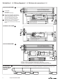
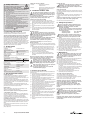
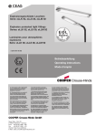
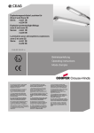
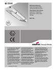
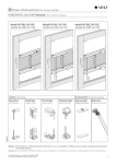
300 8000 1455(D) Betriebsanleitung Explosionsgeschützte Notleuchten Serie: eLLK 92 NIB, eLLM 92 NIB Operating instructions Explosion protected emergency light fittings Series: eLLK 92 NIB, eLLM 92 NIB Mode d’emploi Luminaires de sécurité pour atmosphères explosives Série: eLLK 92 NIB, eLLM 92 NIB CZ: "Tento návod k použití si mĤžete vyžádat ve svém mateĜském jazyce u pĜíslušného zastoupení spoleþnosti Cooper CrouseHinds/CEAG ve vaší zemi." DK: "Montagevejledningen kan oversættes til andre EU-sprog og rekvireres hos Deres Cooper Crouse-Hinds/CEAG leverandør" H: "A kezelési útmutatót az adott ország nyelvén a Cooper Crouse-Hinds/CEAG cég helyi képviseletén igényelheti meg." I: "Se desiderate la traduzione del manuale operativo in un´altra lingua della Comunit à Europea potete richiederla al vostro rappresentante Cooper Crouse-Hinds/CEAG" P: "Se for necessária a tradução destas instruções de operação para outro idioma da União Europeia, pode solicita-la junto do seu representante Cooper Crouse-Hinds/CEAG" PL: Niniejszą instrukcjĊ obsáugi w odpowiedniej wersji jĊzykowej moĪna zamówiü w przedstawicielstwie firmy Cooper-CrouseHinds/CEAG na dany kraj. LT: Šios naudojimo instrukcijos, išverstos Ƴ Jnjsǐ gimtąją kalbą, galite pareikalauti atsakingoje S: "En översättning av denna montage- och "Cooper Crouse-Hinds/CEAG" atstovybơje savo skötselinstruktion till annat EU - språk kan vid šalyje. behov beställas från Er Cooper CrouseHinds/CEAG- representant" LV: "Šo ekspluatƗcijas instrukciju valsts valodƗ EST: "Seda kasutusjuhendit oma riigikeeles varat pieprasƯt jnjsu valsts atbildƯgajƗ Cooper SK: "Tento návod na obsluhu Vám vo Vašom võite küsida oma riigis asuvast asjaomasest Crouse-Hinds/CEAG pƗrstƗvniecƯbƗ." rodnom jazyku poskytne zastúpenie spoloþnosti Cooper Crouse-Hindsi/CEAG esindusest." Cooper Crouse-Hinds/CEAG vo Vašej krajine." FIN: "Tarvittaessa tämän käyttöohjeen käännös M: Jistgƫu jitolbu dan il-manwal fil-lingwa nazzjonali tagƫhom mingƫand ir-rappreĪentant SLO: "Navodila za uporabo v Vašem jeziku on saatavissa toisella EU:n kielellä Teidän lahko zahtevate pri pristojnem zastopništvu Cooper Crouse-Hinds/CEAG - edustajaltanne" ta' Cooper Crouse Hinds/CEAG f'pajjiĪhom. podjetja Cooper Crouse-Hinds/CEAG v Vaši doW(DQFUHLDVTHLPHWDMUDVKWZQRGKJLZQFUKVH NL: "Indien noodzakelijk kan de vertaling van državi." Z9VHDOOKJOZVVDWK9((PSRUHLQD]KWKTHLDSR deze gebruiksinstructie in een andere EU-taal worden opgevraagd bij Uw Cooper CrouseWRQ$QWLSURVZSRWK9Cooper CrouseHinds/CEAG - vertegenwoordiging" Hinds/CEAG? E: "En caso necesario podrá solicitar de su representante Cooper Crouse-Hinds/CEAG estas instrucciones de servicio en otro idioma de la Union Europea" Schaltpläne 1 - 4 / Wiring diagrams 1 - 4 / Schémas de connexions 1- 4 eLLK 92 018/18 NIB 1 1 A Lichtschalter Light Switch Interrupteur d’éclairage B Brücke für Fernschalter, muß beim Anschluß eines Schalters entfernt werden. Link for remote switch, has to be removed while connecting a switch Pont pour l'interrupteur á distance C Nur bei Durchgangsverdrahtung Only in case of through-wiring Seulement en cas d’interconnexion A C 0 + 1 VE/EVG 05218 2 3 Wahlweise für 3-h Betrieb umklemmen To be reconnected for 3 h duration Charger des connexions pour autonomie de 3 h B Netzlampe/mains lamp/lampe-secteur Notlampe/emerg.• lamp/lampe de. sec. eBK 02 eLLM 92 018/18 NIB 2 C 0 A VE/EVG 05218 B Netzlampe/mains lamp/lampe-secteur Notlampe/emerg.• lamp/lampe de. sec. eBK 02 eLLK 92 036/36 NIB 3 L L2 A L Nur bei Durchgangsverdrahtung Only in case of through-wiring Seulement en cas d’interconnexion L1 L3 L1 L2 L3 N N PE PE 0 L1 L N N +B LL LL -B LL LL FS EVG97236 EVG 05236 FS B1 Not B2 VE97236 VE 97236 + LL1 B5 LL1 B4 LL2 B3 C - 1 B6 2 3 Ersatzbruecke fuer Fernschalter muss beim Anschluss eines Schalters entfernt werden Netzlampe/mains lamp/lampe-secteur Netzlampe/Mains lamp Remote Switch, to be removed for connection of B inhibit switch Notlampe/emerg.• lamp/lampe de. sec. Notlampe/Emergency lamp eBK 02 eBK 02 Klemme L dient zur Dauerstromversorgung der Notleuchten. Terminal L serves for permanent current supply of the emergeny luminaires. La borne L sert à l’alimentation en courant permanent des luminaires de sécurité. Fernschalter Remote switch Interrupteur à distance 4 max 10 Notleuchten/ max. 10 emergency light fittings/ 10 luminaires de sécurité au maxi eLLK 92 NIB 2 Cooper Crouse-Hinds GmbH eLLK 92 NIB eLLK 92 NIB eLLK 92 NIB Montagebilder / Illustrations for mounting / Illustrations du montage 1 M8, eLLK 92 12 tief/deep/ profond 188 46 700 (36 W) 400 (18 W) 65 130 Sechskant/Hexagon... SW 13 900 (18 W) 1500 (36 W) 33 33 188 44 20 150 150 76 130 1205 34 880 4a 2 3 4 2 Anschlußraum für ein Kabel Anschlußraum für zwei Kabel Connection compartment for 1 cable Connection compartment for 2 cables Compartiment de raccordement pour 1 câble Compartiment de raccordement pour 2 câbles 4 5 6 ca. 90° 2 1 7 8 9 ca. 90° 1 2 10 8.1 11 9.1 12 ≥ 2 mm Cooper Crouse-Hinds GmbH 3 Netzbetrieb Notbetrieb (interne Batterie) eLL.92 eLL.92 eLL.92 eLL.92 36W NIB 18W NIB 36W NIB 18W NIB Störfestig- erfüllt keit nach EN 50 082-2 erfüllt erfüllt erfüllt Störauserfüllt sendung nach EN 50 081-2 (Industriebereich) erfüllt erfüllt Überschreitung im Frequenzbereich 300650 kHz um max. 4 dB Elektrische Daten: Ausführung Spannungsbereich AC ± 10% 2x18 W 2x36 W 110-127 V (Sonderausf.) 110-127 V (Sonderausf.) 220-254 V 220-254 V Frequenzbereich Mains operation 47-63Hz cos ϕ (Nennspannung 110 V) cos ϕ (Nennspannung 230 V) Nennstrom in A bei: 110 V AC 127 V AC 230 V AC 254 V AC Lichtstromfaktor (Notlicht): bezogen auf 1 Lampe bei Nennbetrieb >0,95 >0,95 >0,95 >0,95 0,46 0,44 0,23 0,21 bei 1,5h ca. 90% bei 3,0h ca. 45% >0,8 >0,7 >0,4 >0,37 bei 1,5h ca. 45% bei 3,0h ca. 25% Emergency operation (built-in battery) eLL.92 eLL.92 eLL.92 eLL.92 36W NIB 18W NIB 36W NIB 18W NIB Immunity fulfilled fulfilled fulfilled fulfilled from interference to EN 50 082-2 Emission fulfilled fulfilled fulfilled Deviation of interby max. ferences to 4 dB in EN 50 081-2 the (industrial frequency area) range 300650 kHz Electrical data: Version Voltage range AC ± 10% Frequency range 2x36W 110-127 V (special vers.) 220-254V 110-127V (special vers.) 220-254V 47-63Hz cos ϕ (rated voltage 110V) cos ϕ (rated voltage 230V) Rated current in A at: 110V 127V 230V 254V 2x18W AC AC AC AC Luminous flux factor (emerg. light) related to 1 lamp in rated operation: >0.95 >0.95 >0.95 >0.95 0.46 0.44 0.23 0.21 0.8 0.7 0.4 0.37 at 1.5h apx. 90% at 3.0h apx. 45% at 1.5h apx. 45% at 3.0h apx. 25% Fonctionnement Fonctionnement en sur secteur éclairage de secours (batterie incorporée) eLL.92 eLL.92 eLL.92 eLL.92 36W NIB 18W NIB 36W NIB 18W NIB Antiparasi- rempli tage selon EN 50 082-2 rempli rempli rempli Emission de remplie remplie remplie Dépasseparasites ment de selon 4dB au EN 50 081-2 maxi (domaine dans la industriel) gamme des fréquences de 300 à 650 kHz 4 Cooper Crouse-Hinds GmbH Caractéristiques électriques: Modèle Gamme des tensions CA ± 10% Gamme des fréquences cos ϕ (tens. nom. 110V) cos ϕ (tens. nom. 230V) Courant nom. en A à: 110V CA 127V CA 230V CA 254V CA Facteur de flux lumineux (éclairage de secours): par rapport à 1 lampe en service nominal 2x18W 2x36W 110-127 V 110-127V (exécution spéciale) (exécution spéciale) 220-254V 220-254V 47-63Hz >0,95 >0,95 >0,95 >0,95 0,46 >0,8 0,44 >0,7 0,23 >0,4 0,21 >0,37 à 1,5h env. 90% à 1,5h env. 45% à 3,0h env. 45% à 3,0h env. 25% 1. Sicherheitshinweise: Zielgruppe: Elektrofachkräfte und unterwiesene Personen. Die Leuchte darf nicht in den Zonen 0 und 20 eingesetzt werden! Das Betriebsmittel darf nicht bei Staubablagerungen übermäßiger Dicke (≥ 50 mm, gem. EN 50281-1-2) betrieben werden. Die auf der Leuchte angegebenen technischen Daten sind zu beachten! Umbauten oder Veränderungen an der Leuchte sind nicht zulässig! Die Leuchte ist bestimmungsgemäß in unbeschädigtem und einwandfreiem Zustand zu betreiben! Als Ersatz dürfen nur Originalteile von Cooper Crouse-Hinds (CCH)/CEAG verwendet werden! Reparaturen, die den Explosionsschutz betreffen, dürfen nur von CCH/CEAG oder einer qualifizierten „Elektrofachkraft“ durchgeführt werden! Diese Betriebsanleitung während des Betriebes nicht in der Leuchte lassen! Die nationalen Unfallverhütungs- und Sicherheitsvorschriften und die nachfolgenden Sicherheitshinweise, ) die in dieser Betriebsanleitung mit einem ( gekennzeichnet sind, beachten! 2. Normenkonformität 2. Abhängige Betriebsart Durch Entfernen der Brücke 2-3 (siehe Schaltplan 1 und 3) oder S1-S2 kann bei Netzausfall die Notlichtfunktion über einen extern installierten Fernschalter separat ein- und ausgeschaltet werden. Der externe Fernschalter ist an den Klemmen 2-3 (eLLK 92) bzw. S1 und S2 (eLLM 92) zu installieren. Es sind max. 10 Leuchten an einen Fernschalter anschließbar (Schaltplan 4). Einstellung der Notlicht-Betriebsdauer: 1,5 Stunden: Beide Leitungen an Klemme 1 anschließen. 3,0 Stunden: Eine Leitung an Klemme 1 und eine Leitung an Klemme 0 anschließen, (Schaltplan 1, 2 und 3). 5. Installation eLLK 92 ... NIB Die für das Errichten und Betreiben von explosionsgeschützten elektrischen Betriebsmitteln geltenden Sicherheitsvorschriften gemäß des Gerätesicherheitsgesetzes sowie die allgemein anerkannten Regeln der Technik sind einzuhalten! Transport und Lagerung der Leuchte ist nur in Originalverpackung und der angegebenen Lage gestattet! Achtung! Aufgrund der Selbstentladung der Batterie ist nach spätestens 6 Monaten auch bei nicht angeschlossenen Leuchten die Batterie mindestens 14 Stunden nachzuladen. Achtung! Zeigt der Lichtaustritt nach oben sind zusätzliche Schutzmaßnahmen gegen dauerhafte Wasseransammlungen im Bereich der Wannendichtung zu treffen. Diese Leuchte ist zum Einsatz in explosionsgefährdeten Bereichen der Zone 1,2, 21 und 22 gemäß EN 60079-10 und IEC 61241-10 geeignet. Das eingebaute EVG 05 erfüllt die Anforderungen des Entwurfs IEC 60079-7 -4 Ausgabe (EOL) und den Anforderungen der IEC 61347-2-3 (§17.2 und §17.3). Sie wurde entsprechend dem Stand der Technik und gemäß DIN EN ISO 9001:2000 entwickelt, gefertigt und geprüft. Öffnen und Schließen der Leuchte: Den Zentralverschluss mit Steckschlüssel (Schlüsselweite SW 13) um 90° bis zur Raststellung drehen und Schutzwanne abklappen (Bild 3). Schutzwanne ein- und ausbauen (Bild 6 und 7). Die Schutzwanne ist wahlweise beidseitig scharnierbar. Schutzwanne zum Verschließen der Leuchte fest an das Leuchtengehäuse andrücken und den Zentralverschluss um 90° drehen. Im Netzbetrieb werden alle Anforderungen der Normen voll eingehalten. Im Notlichtbetrieb wird der in der Norm festgelegte Wert der Störaussendung in einem gewissen Frequenzbereich geringfügig überschritten. Diese Überschreitung führt bei bestimmungsgemäßem Gebrauch der Leuchte zu keinerlei Beeinträchtigung anderer Betriebsmittel. Achten sie auf die plane Anbringung der Leuchte zur Sicherstellung der Schutzart, siehe Bild 10-12! Beachten Sie beim Befestigen des Montagezubehörs an der Leuchte die max. Gewindetiefe der Montagebohrung von 12 mm! Verwenden Sie keine zu langen Schrauben! 3. Technische Daten Montagezubehör: siehe CCH/CEAG Katalog. EG-Baumusterprüfbescheinigung: PTB 96 ATEX 2144 Konformität gemäß Richtlinie 94/9/EG (Gas): II 2 G EEx edm ib IIC T4 (Staub) II 2 D IP 66 T 80°C Zündschutzart: EEx edm ib IIC T4 Anerkennung der Qualitätssicherung Produktion: PTB 96 ATEX Q001-1 Schutzklasse nach EN 60 598: I Klemmvermögen Anschlußklemme 2x je Klemme: einadrig mehradrig min.: 1,5 mm2 2,5 mm2 max.: 6,0 mm2 4,0 mm2 Leiterquerschnitt bei Durchgangsverdrahtung: 2,5 mm2 für max. 16A EEx e-Kabel- und Leitungseinführung Standardausführung: M25x1,5 für Leitungen Ø 8 bis 17 mm Metall: M20x1,5 Gewinde Drehmoment für EEx-e-Kabelund Leitungseinführung M25x1,5: 5,0 Nm Drehmoment für Druckschraube: 3,5 Nm (für Abdichtung Leitung oder Verschlußstopfen) Netzanschluss: Zum Öffnen des Anschlussraumes grünen Drehgriff in Pfeilrichtung bis zum Anschlag drehen, dann ziehen und die Klappe abklappen (Bild 4 und 5). 4. Funktionelle Besonderheiten 5.1 Installation eLLM 92 ...NIB Ladung der Batterie Bei Netzbetrieb wird die Batterie der Leuchte durch ein Konstantstrom-Ladeteil geladen. Die Ladung erfolgt über den ungeschalteten Außenleiter L, damit sie auch bei ausgeschalteter Leuchte nicht unterbrochen wird. Der Ladestrom ist bei ordnungsgemäßem Betrieb der Leuchte so bemessen, dass bei entladener Batterie innerhalb von 14 h ca. 90% der Nennkapazität erreicht werden. Er ist für eine Dauerladung der Batterie geeignet. Der Tiefentladeschutz mit Wiedereinschaltsperre überwacht im Notbetrieb die Batteriespannung und verhindert die Tiefentladung der Zellen. Betriebsarten Bei anliegender Netzspannung können die Lampen in der Leuchte mit dem Leuchtenschalter ein- und ausgeschaltet werden. Für Notlicht gibt es zwei Betriebsarten 1. Unabhängige Betriebsart Ist zwischen den Klemmen 2-3 (Schaltplan 1 und 3) eine Brükke eingesetzt, so erfolgt bei Netzausfall automatisch eine Umschaltung auf Notlichtbetrieb. Bei der Mastleuchte eLLM 92 ist diese Brücke an den Klemmen S1 und S2 (Schaltplan 2). Die Leitung durch die EEx-Kabel- und Leitungseinführung einführen (Bild 5). Für Leitungen von Ø 8 bis 12 mm beide Dichtungseinsätze, von Ø 12 bis 17 mm nur den äußeren Dichtungseinsatz verwenden. Auf korrekten Sitz des verbleibenden Dichtungseinsatzes in der Verschraubung achten. Die Leitungen an den Anschlussklemmen PE, N, L1, L, (L2, L3) gemäß Klemmenbezeichnung anklemmen (Schaltpläne, Seite 2). Auch nicht benutzte Klemmen anziehen! Achtung: Ladeleitung L und Netzanschluss der Leuchte müssen stets auf demselben Außenleiter des Netzes liegen! Achtung: Bei nicht benutzten Kabel- und Leitungseinführungen ist die Schutzscheibe zu entfernen und die Einführung durch einen Verschlussstopfen (Drehmoment 3,5 Nm) zu verschließen. Beim Verschließen mit einem Verschlussstopfen stets beide Dichtungseinsätze verwenden! Bei Metall-Kabeleinführungen sind die Schutzkappen der nicht benutzten Einführungen zu entfernen und diese durch bescheinigte EEx-Verschlussstopfen zu verschließen! Die Montage und Installation der Mastleuchte erfolgt in folgender Reihenfolge: Die drei Kreuzschlitzschrauben im Deckel des Mastanschlussraumes lösen (Bild 2, Pos. 1). Anschlussraum durch Aufklappen des Deckels öffnen (Bild 2, Pos. 2). Verriegelungsbügel des Kabel- und Leitungseinführungsstutzens bis zum Anschlag hochziehen und Abdeckplatte abnehmen (Bild 2, Pos. 3). Kabel- und Leitungseinführungsstutzen aus den Führungsnuten im Anschlussraum entnehmen. Mastrohr oder das Rohr des Wandarmes von jeweils Ø 42 mm (Bild 2, Pos. 4) bis zum Anschlag in die Öffnung der Mastleuchte einführen (Bild 2, Pos. 4a). Leuchte ausrichten und die vormontierten Spezialschrauben M6 anziehen (Drehmoment 3,0 Nm, Bild 2, Pos. 5). Leitung durch das Rohr einführen und auf die entsprechende Länge abisolieren. Leitung durch die EEx-Kabel- und Leitungseinführung (KLE) einführen und mit der Druckschraube der KLE die Leitung anziehen (Drehmoment 3,5 Nm). Kompletten Träger (mit eingeführter Leitung) in die Führungsnuten der Mastleuchte einsetzen (Bild 2, Pos. 6). Träger mit Verriegelungsbügel verschließen (Bild 2, Pos. 3). Leitung in die Zugentlastung legen und anziehen (Bild 2, Pos. 7). Leitung entsprechend der Klemmenbezeichnung anschließen. Einsetzen der Lampe: Nur solche Lampen verwenden, die für diese Leuchte zugelassen sind, siehe Technische Daten und Typenschild! T12-Lampen (Ø 38 mm) werden von der EOL-Schaltung als fehlerhaft erkannt und abgeschaltet! Einstiftsockellampe (Fa6) Lampe erst auf der einen Seite in die Fassung stecken. Danach die gegenüberliegende Fassung etwas nach außen ziehen und die Lampe einstecken (Bild 8.1 und 9.1). Zweistiftsockellampe (G13) Lampe in beide Fassungen bis zum Anschlag einstecken (Bild 8), so dass an jeder Seite der Lampe beide Stifte im Eingriff der Fassung sind. Danach die Lampe um 90° in Raststellung drehen (Bild 9), wobei die grüne Fläche in der Fassung sichtbar wird. Die Lampe ist nun gegen Herausfallen gesichert. 6. Inbetriebnahme Vor der Inbetriebnahme die korrekte Funktion und Installation der Leuchte in Übereinstimmung mit dieser Betriebsanleitung und anderen zutreffenden Bestimmungen überprüfen! Isolationsmessungen nur zwischen PE und Außenleiter L1 (L, L2, L3) sowie zwischen PE und N durchführen! – Meßspannung: max. 1kV AC/DC – Messstrom: max. 10 mA Achtung: Eine Isolationsmessung zwischen L und N darf nicht durchgeführt werden, da sonst die Elektronik oder die Netzeingangssicherung im VE-Gerät) zerstört wird. Leuchte verschließen. Bei der Mastleuchte (eLLM 92...) ist der Anschlussraum durch die vorher entfernte Abdeckplatte wieder abzudecken. Hierzu Verriegelungsbügel des Kabel- und Leitungseinführungsstutzens hochziehen (Bild 2, Pos.3) und die Abdeckplatte sowie den Kabel- und Leitungseinführungsstutzen mit dem Verriegelungsbügel festklemmen. Mit den drei Kreuzschlitzschrauben den Deckel des Anschlussraumes wieder verschließen. Die Netzspannung zu- und die Leuchte einschalten. Die Leuchte mindestens 14 h eingeschaltet lassen, damit die Batterie aufgeladen wird. Danach einen Funktionstest der Notlichtschaltung durchführen, (siehe 7. Instandhaltung, Funktionstest). 7. Instandhaltung Die für die Instandhaltung, Wartung und Prüfung von explosionsgeschützten Betriebsmitteln geltenden Bestimmungen sind einzuhalten! Wartung Im Rahmen der Wartung sind vor allem die Teile, von denen die Zündschutzart abhängt, zu prüfen z. B.: Gehäuse und Schutzwannen auf Risse und Beschädigungen. Dichtungen auf Beschädigungen. Klemmen und Verschlussstopfen auf festen Sitz. Wegen der Gefahr elektrostatischer Aufladung darf die Leuchte nur mit einem feuchten, nicht fasernden Tuch oder Schwamm gereinigt werden! Dazu nur übliche Haushaltsspülmittel in Verdünnung mit Wasser benutzen! Die Wassertemperatur darf maximal 50°C betragen. Anschließend mit klarem Wasser nachspülen, da sonst Spannungsrisse in der Schutzwanne entstehen können! Die Lampenwechselintervalle der Lampenhersteller sind zu beachten! Funktionstest Notlicht Netzspannung der Leuchte ausschalten. Die Notlichtlampe (rote Fassung) muss leuchten. Folgende Prüfzeiten sollten bei einem Funktionstest nicht überschritten werden, das sonst keine Notlichtreserve zur Verfügung steht: Batteriesatz mit 1,5 h Notlicht: 60 min. Batteriesatz mit 3,0 h Notlicht: 120 min. Erlischt die Notlichtlampe bei vollgeladener Batterie innerhalb dieser Prüfzeit, ist ein neuer Batteriesatz einzusetzen. Hinweis: Die volle Batteriekapazität steht physikalisch bedingt erst nach ca. 3 Lade/Endladezyklen zur Verfügung! Instandsetzung Vor dem Austausch oder der Demontage von Einzelteilen ist folgendes zu beachten: Das Betriebsmittel vor dem Öffnen oder vor Instandhaltungsarbeiten erst spannungsfrei schalten! Nur zugelassene CCH/CEAG Originalersatzteile verwenden (siehe CCH/CEAG Ersatzteilliste). Programmänderungen und -ergänzungen sind vorbehalten. Bei der Entsorgung nationale Abfallbeseitigungsvorschriften beachten! Cooper Crouse-Hinds GmbH 5 1. Safety instructions For skilled electricians and trained personnel in accordance with national legislation, including the relevant standards and, where applicable, in acc. with IEC 60079-17 on electrical apparatus for explosive atmospheres. The light fitting must not be operated in zone 0 or zone 20 hazardous areas! The technical data indicated on the light fitting are to be observed! Changes of the design and modifications to the light fitting are not permitted! The light fitting shall be operated as intended and only in an undamaged and perfect condition! Only genuine Cooper Crouse-Hinds (CCH)/CEAG spare parts may be used for replacement! Repairs that affect the explosion protection, may only be carried out by CCH/CEAG or a qualified "electrician”! These operating instructions shall not be kept inside the light fitting during operation! The national safety rules and regulations for preven-tion of accidents and the following safety instructions which are marked with an ( ) in these operating instructions shall be observed! 2. Conformity with standards The light fitting is suitable for use in zone 1, 21, 2 and 22 hazardous areas acc. to EN 60079-10 and IEC 61241-10. The built-in EVG 05 fulfills the requirements of the draft IEC 60079-7 Ed. 4 (EOL) and the IEC 61347-2-3 (§17.2 and §17.3). It has been designed, manufactured and tested according to the state of the art and according to DIN EN ISO 9001: 2000. All requirements of the standards are fully kept in mains operation. In the event of interferences being emitted in emergency operation, there will be a slight upper deviation from the value defined in the standard in a certain frequency range. That deviation does not entail any impairment of any other apparatus, if the luminaire is duly operated. 3. Technical data EC type sample test certificate: PTB 96 ATEX 2144 Conformity acc. to directive 94/9/EC (gas): II 2 G EEx edm ib IIC T4 (dust) II 2 D IP 66 T 80°C Approval of the production quality assurance: PTB 96 ATEX Q001-1 Explosion category: EEx edm ib IIC T4 Insulation class to EN 60 598: I Supply terminal clamping capacity 2 x per terminal: single-wire multi-wire min. 1.5 mm2 2.5 mm2 max. 6.0 mm2 4.0 mm2 Conductor cross-section with through-wiring: 2.5 mm2 for max. 16 A EEx-e cable entry standard version: M25x1.5 for cable Ø (8 to 17 mm) metal thread: M20x1.5 Torque for M 25 x 1.5 EEx-e cable entry: 5.0 Nm Torque for pressure screw: 3.5 Nm (for sealing off the cable or the blanking plug) 4. Special functional features Charging the battery In mains operation the light fitting is charged by means of a constant current charger. Charging takes place via the unswitched external phase L to prevent an interruption, even when the luminaire is switched off. With regular operation of the light fitting the charging current is measured so that a flat battery will have obtained apx. 90 % of its rated capacity within 14 h. It is suitable for a continuous charge of the battery. In emergency operation a deep discharge protection with reclosure preventing device monitors the battery voltage and prevents the accumulators’deep discharge. System modes When voltage applies, the lamps in the light fitting can be switched on and off with the light switch. There are two system modes for emergency operation 1. Independent system mode: If the terminals on the terminal block 2-3 (wiring diagrams 1 and 3) are bridged, there will be an automatic changeover to emergency operation in the event of a mains failure. On the eLLM92 pole mounted light fitting this bridge is established on the terminals S1 and S2 (wiring diagram 2). 2. Dependent system mode When removing the bridge 2-3 (wiring diagrams 1 and 3) the emergency light function can be separately switched on and off via a remote switch installed outside in the event of a mains failure. Connect the remote switch to terminal 2-3 (eLLK 92) or to S1 and S2 (eLLM 92). Max. 10 luminaires can be connected to one remote switch (wiring diagram 4). 6 Cooper Crouse-Hinds GmbH Setting the emergency duration 1.5 hours: Connect both conductors under terminal 1. 3.0 hours: Connect one conductor under terminal 1 and one conductor under terminal 0, (wiring diagrams 1, 2 or 3). 5. Installation eLLK 92 ...NIB The respective national regulations as well as the general rules of engineering which apply to the installation and operation of explosion protected apparatus, will have to be observed! Transport and storage of the luminaire is permitted in original packing and specified position only! Opening and closing the light fitting Turn the central locking device with a box spanner (opening of the spanner SW 13) through 90° to its lock-in position and fold down the protective bowl, see fig. 3. Fit in and remove the protective bowl acc. to fig. 6 and 7. The protective bowl can, at option, be hinged on either side. To close the light fitting, press the protective bowl tightly onto the luminaire housing and turn the central locking device through 90°. Mounting: see fig. 1 The integrity of the fitting may be compromised if the fixing centres are not correctly aligned, see fig. 10-12. When fixing the mounting accessories onto the light fitting, observe the max. depth of thread of 12 mm! Do not use too long screws! Installing the light output upwards additional protection has to be assembled to avoid permanent water accumulations at the protective bowl gasket area. Accessories for mounting: See CCH/CEAG catalogue. Mains connection To open the connection box, turn the green handle to its stop in the direction of arrow, then pull it and fold down the flap (fig. 4 and 5). Introduce the cable through the EEx cable entry (fig. 5). Use both sealing inserts for cables from 8 to 12 mm Ø, and the outer sealing insert only for cables from 12 to 17 mm Ø. Pay attention to the proper fit of the sealing insert remaining in the cable gland. Connect the conductors to the terminals PE, N, L1, L, (L2, L3) in accordance with the terminal marking (wiring diagrams, page 2). Also tighten vacant terminals! Mind: The charging conductor L and the luminaire’s mains connection must always be connected to the same external conductor of the mains supply! Attention: In case of unused cable entries, remove their protective cover and close the entries with a blanking plug (torque of 3.5 Nm). When closing the gland with a blanking plug, always use both sealing inserts! When metal cable entries are used, the protective caps of the unused entries are to be removed and the entries to be closed with certified EEx blanking plugs! 5.1 Installation of the eLLM 92 NIB The pole mounted light fitting is mounted and installed in the following order: Unscrew the three recessed head screws in the cover of the pole connecting compartment (fig. 2, item 1). Open the connecting compartment by folding down the cover (fig. 2, item 2). Pull the stay shackle of the cable entry socket up to its stop and take off the cover plate (fig. 2, item 3). Remove the cable entry sockets from the guiding grooves in the connecting compartment. Then the pole mounting tube or the tube of the wall socket of 42 mm [ each (fig. 2, item 4) is pushed home into the opening of the light fitting (fig. 2, item 4a). Adjust the light fitting and screw down the preassembled M 6 special screws (torque of 3.0 Nm, fig. 2, item 5). Introduce the cable through the tube and strip the insulation to the required length. Introduce the cable through the EEx cable entry (KLE) and tighten it with the pressure screw of the cable entry (torque of 3.5 Nm). The complete support (with the cable being introduced) is put into the guiding grooves of the pole mounted light fitting (fig. 2, item 6). Lock the support with the stay shackle (fig. 2, item 3). Insert the cable into the pull-relief and tighten it (fig. 2, item 7). Then connect the cable in accordance with the terminal marking. Inserting the lamp Only use such lamps that have been certified for these light fittings, see technical data and type label! T12-lamps (Ø 38 mm) will be detected as faulty and will be cut off by the EOL-circuit Single-pin lamp (Fa6) First insert one side of the lamp into the lampholder. Then pull the opposite lampholder slightly outwards and insert the lamp (fig. 8.1 and 9.1). Bi-pin lamp (G13) The lamp is to be inserted to its stop into both holders (fig. 8), so that both pins on either side of the lamp engage in the holder. Then turn the lamp through 90° to its lock-in position (fig. 9), the green surface in the holder getting visible. Now the lamp is secured against falling out. 6. Taking into operation Prior to operation, check the light fitting for its proper functioning and installation in compliance with these operating instructions and other applicable regulations! Only carry out insulation measurements between PE and the external conductor L1 (L, L2, L3) as well as between PE and N. – measuring voltage: – measuring current: max. 1 kV AC/DC max. 10 mA Mind: There must no insulation measurement be carried out between L and N, since that would destroy the electronics (mains input fuse in the VE unit). Then the luminaire will have to be closed. The terminal compartment of the pole mounted light fitting (eLLM 92..) is again to be covered with the cover plate that was previously removed. To that effect, pull up the stay shackle of the cable entry socket (fig. 2, item 3) and clamp down the cover plate and the cable entry socket with the stay shackle. Again screw down the cover of the terminal compartment with the three recessed head screws. Switch on the mains voltage and then the light fitting. Leave the light fitting switched on for at least 14 hours so that the battery will be recharged. After that, release a function test of the emergency light connection, see 7. Maintenance, function test. 7. Maintenance The national regulations applicable to the maintenance, servicing and test of apparatus for explosive atmospheres as well as the general rules of engineering will have to be observed! Servicing: When servicing, in particular those components that affect the explosion protection, will have to be checked, e. g.: Housing and protective bowl for any cracks or damages. Gaskets for their perfect condition. Terminals and blanking plugs for their firm fit. Because of the risk of an electrostatic charge, the light fitting shall only be cleaned with a damp, non-fibrous cloth or sponge! Only use customary household washing-up liquid diluted in water! The water temperature may be max. 50°C. After that, rinse with clear water to prevent the risk of tension cracks in the protective bowl! Lamp replacement: Keep replacement intervals as specified by the lamp manufacturer! Test of the emergency light function Switch the luminaire off the mains voltage. The emergency lamp (red lampholder) must light. A function test should not exceed the following test periods: Battery set for 1.5 h emergency light: 60 min. Battery set for 3.0 h emergency light: 120 min. Should the emergency lamp be extinguished within the test period though the battery is fully charged, the latter will have to be replaced by a new battery set. Mind: The full battery capacity will be available after approx. 3 charging/discharging cycles due to physical behaviour. Repair: Prior to replacing or removing any components, observe the following: Cut the apparatus off the voltage before opening or servicing it! Only use certified genuine CCH/CEAG spare parts! (See CCH/CEAG spare parts list). Subject to alteration or supplement of this product series. Regarding waste disposal, observe the relevant national regulations! The plastic materials are marked with the relevant labels. 1. Consignes de sécurité Pour le personnel électricien qualifié et le personnel instruit suivant la règlementation légale, y compris les normes respectives ainsi que, le cas échéant, CEI 60079-17 pour apppareils électriques utilisables en atmosphère explosive. Il n’est pas permis d’utiliser le luminaire dans la zone 0 et zone 20! L’appareil ne doit pas être mis en marche lorsque l’épaisseur du dépôt de poussière est trop importante (supérieur ou égal à 50 mm, selon EN 50281-1-2). Les caractéristiques techniques indiquées sur le luminaire doivent être respectées! Il n’est pas permis de transformer ou de modifier le luminaire! Le luminaire ne doit être exploité que pour la fonction qui lui est dévolue et qu’en état intact et parfait! Seules des pièces de rechange d’origine Cooper Crouse-Hinds (CCH)/CEAG doivent être employées pour le remplacement! Des réparations qui portent sur la protection contre l’explosion, ne doivent être exécutées que par CCH/ CEAG ou par un «électricien» qualifié.! Ce mode d’emploi ne doit pas être laissé dans le luminaire pendant son exploitation! Veuillez respecter les prescriptions nationales de sécurité et de prévoyance contre les accidents ainsi que les consignes de sécurité qui sont marquées d’un ( ) dans ce mode d’emploi! 2. Conformité avec les normes Ce luminaire convient à l’utilisation dans les zones 1, 2 , 21 et 22 d’une atmosphère explosive selon EN 60079-14 et CEI 61241-10. Le EVG 05 intégré remplit les conditions du CEI 60079-7 ED. d'ébauche 4 (EOL) et le CEI 61347-2-3 (§17.2 et §17.3). Il a été conçu, construit et testé selon l’état actuel de la technique et selon DIN EN ISO 9001:2000. Lorsque les luminaires fonctionnent sur secteur, toutes les exigences des normes sont entièrement remplies. En cas d’émission de parasites en exploitation d’éclairage de secours, la valeur définie dans la norme sera dépassé un peu dans une certaine gamme des fréquences. Si le luminaire est proprement exploité, ce dépassement n’aura aucun effet préjudiciable sur d’autres appareils. 3. Caractéristiques techniques Certificat d’essai CE du modèle type: Conformité avec la PTB 96 ATEX 2144 directive 94/9/CE (gaz): II 2 G EEx edm ib IIC T4 (poussière) II 2 D IP 66 T 80°C Homologation de l’assurance de la qualité en production: PTB 96 ATEX Q001-1 Mode de protection: EEx edm ib IIC T4 Classe d’isolation selon EN 60 598: I Capacité de serrage des bornes, 2 x par borne: unifilaire multifilaire min. 1,5 mm2 2,5 mm2 max. 6,0 mm2 4,0 mm2 Section transversale du conducteur en 2 2,5 mm pour 16 A au maxi cas d’interconnexion: Entrée de câble EEx-e: modèle standard M25x1,5 pour câbles d’un modèle standard d’un Ø de 8 à 17 mm Couple pour l’entrée de câble EEx-e M25x1,5: 5,0 Nm Couple pour la vis de 3,5 Nm pression: (pour étancher le câble ou le bouchon de fermeture) 4. Particularités fonctionnelles Charge de la batterie En cas de fonctionnement sur secteur, la batterie du luminaire est chargée par un chargeur à courant continu. La charge se fait par la phase L non commutée afin de ne pas l’interrompre, lorsque le luminaire a été mis hors service. Lors d’une exploitation régulière du luminaire, le courant de charge est mesuré tel qu’environ 90% de la capacité nominale d’une batterie déchargée soient obtenus en 14 heures. Il convient à une charge continue de la batterie. En service d’éclairage de sécurité, la protection de fin de décharge avec barrage de réenclenchement surveille la tension de batterie et prévient la décharge profonde des accumulateurs. Modes de couplage Le secteur présent, les lampes dans le luminaire peuvent être allumées et éteintes avec l’interrupteur d’éclairage. Il y a deux modes de couplage pour l’éclairage de secours 1. Mode indépendant Si les bornes du bornier 2-3 (schémas des connexions 1 et 3) sont pontées, une commutation automatique en éclairage de secours se fera automatiquement en cas d’une panne de secteur. Au luminaire eLLM 92 ce pont est installé aux bornes S1 et S2 (schéma des connexions 2). 2. Mode dépendant Si le pont 2-3 (schémas des connexions 1 et 3) ou S1-S2 est enlevé, la fonction d’éclairage de secours peut être enclenchée ou déclenchée séparément à l’aide d’un interrupteur à distance installé à l’extérieur. L’interrupteur à distance doit être connecté à la borne 2-3 (eLLK 92) ou aux bornes S1 et S2 (eLLM 92). 10 luminaires au maxi peuvent être connectés à un interrupteur à distance (schéma des connexions 4). Réglage de l’autonomie de l’éclairage de secours: 1,5 heures: 3,0 heures: Raccorder les deux conducteurs sous la borne 1. Raccorder un conducteur sous la borne 1 et 1 conducteur sous la borne 0 (schémas des connexions 1 et 2). 5. Installation eLLK 92 ...NIB Lors de l’installation et de l’exploitation des appareils électriques pour atmosphère explosive, les règlements nationaux ainsi que les règles de la technique généralement reconnues doivent être respectés! Le transport et le stockage ne sont permis que dans l’emballage original et dans la position spécifiée! Ouverture et fermeture du luminaire Tourner le verrou central avec la clé à douille (ouverture de clé SW 13) de 90°dans sa position de crantage et rabattre la vasque de protection, voir fig. 3. Monter et démonter la vasque de protection suivant fig. 6 et 7. La vasque de protection est pourvue d’une charnière des deux côtés ce qui permet de la suspendre de chaque côté. Pour fermer le luminaire, presser la vasque de protection contre le boîtier du luminaire et tourner le verrou central de 90°. Dimensions de fixation: voir fig. 1 L'intégrité de l'ajustage de précision peut être compromise si les centres de réparation ne sont pas correctement alignés, voir fig. 10-12. Respecter lors de la fixation des accessoires de montage au luminaire que les trous de fixation doivent avoir une profondeur du pas de 12 mm au maxi. Si le luminaire est installé avec la vasque vers le haut, des précautions devront être prises pour éviter l’accumulation d’eau au niveau du joint de la vasque. Ne pas utiliser de vis trop longues! Accessoires pour le montage: voir le catalogue CCH/CEAG. Branchement sur secteur Afin d’ouvrir la boîte de connexion, tourner la poignée vert jusqu’à sa butée, puis la tirer et rabattre la trappe (fig. 4 et 5). Introduire le câble par l’entrée de câble EEx-e (fig. 5). Utiliser les deux joints d’étanchéité pour les câbles Ø de 8 à 12 mm, et le joint extérieur seul pour les câbles Ø de 12 à 17 mm. Veiller au propre logement du joint d’étanchéité resté dans la presse-étoupe. Connecter les câbles aux bornes PE, N, L1, L, (L2, L3) suivant le repérage des bornes (schéma des connexions sur page 2). Serrer aussi les bornes non utilisées! Attention: Le raccordement du fil de charge L et le branchement sur secteur du luminaire doivent toujours être établis sur le même conducteur extérieur du secteur! Attention En cas d’entrées de câble non utilisées, leur disque protecteur doit être enlevé, et l’entrée doit être fermée avec un bouchon de fermeture (couple de 3,5 Nm). Lorsqu’ un bouchon de fermeture est mis, toujours utiliser les deux joints d’étanchéité! En cas d’entrées de câble métalliques, enlever les obturateurs protecteurs des entrées non utilisées et les fermer avec des bouchons de fermeture EEx certifiés! 5.1 Installation eLLM 92 ...NIB Le montage et l’installation du luminaire pour fixation sur mât se fait dans l’ordre suivant: Dévisser les trois vis à fentes en croix dans le couvercle du compartiment de raccordement du poteau (fig. 2, pos. 1). Ouvrir le compartiment de raccordement en rabattant le couvercle (fig. 2, pos. 2). Lever l’étrier de verrouillage de la tubulure d’entrée de câble jusqu’à sa butée et enlever la plaque de recouvrement (fig. 2, pos. 3). Sortir la tubulure d’entrée de câble des rainures de guidage dans le compartiment de raccordement. Introduire le tube du poteau ou de la console d’un diamètre de 42 mm chacun (fig. 2, pos. 4) jusqu’à la butée dans l’orifice du luminaire (fig. 2, pos. 4a). Ajuster le luminaire et serrer à fond les vis spéciales M6 montées au préalable avec un couple de 3,0 Nm (fig. 2, pos. 5). Puis introduire le câble par le tube et le dénuder de la longueur requise. Introduire le câble par l’entrée de câble EEx (KLE) et le serrer à fond au moyen de la vis de pression de l’entrée de câble (couple de 3,5 Nm). Puis le support complet (avec le câble mis en place) est posé dans les rainures de guidage du luminaire pour fixation sur mât (fig. 2, pos. 6). Verrouiller le support au moyen de l’étrier de verrouillage (fig. 2, pos. 3). Poser le câble dans la décharge de traction et le serrer à fond (fig. 2, pos. 7). Puis raccorder à vis le câble suivant le repérage des bornes. Mise en place de la lampe N’utiliser que des lampes homologuées pour ces luminaires, voir Caractéristiques techniques et plaque signalétique! Les lampes T12 (Ø 38 millimètres) sera détecté en tant que défectueux et découpé par l'EOL-circuit. Lampe monobroche (Fa6) Introduire la lampe d’un côté dans la douille. Puis tirer un peu vers l’extérieur la douille opposée et insérer la lampe (fig. 8.1 et 9.1). Lampe double broche (G13) Introduire la lampe jusqu’à sa butée dans les deux douilles selon fig. 8, de manière que les deux broches de chaque côté de la lampe soient prises par la douille. Puis tourner la lampe de 90° en sa position de crantage (fig. 9). Une surface verte dans la douille deviendra alors visible. Maintenant la lampe est protégée de tomber du luminaire. 6. Mise en service Avant la mise en service du luminaire, il faut vérifier s’il est branché et fonctionne en conformité avec ce mode d’emploi et avec d’autres règlements y applicables! Des mesurages d’isolation ne doivent être effectués qu’entre PE et le conducteur extérieur L1 (L, L2, L3) ainsi qu’entre PE et N! – tension de mesurage: 1 kV CA/CC au maxi – courant de mesurage: 10 mA au maxi Il n’est pas permis d’effectuer un mesurage d’isolation entre L et N puisque cela détruirait l’électronique (fusible d’entrée secteur dans le bloc VE). Puis fermer le luminaire. Le compartiment de raccordement du luminaire pour fixation sur mât (eLLM 92..) doit être recouvert de la plaque de recouvrement qui était enlevé auparavant. Pour cela, lever l’étrier de verrouillage de la tubulure d’entrée de câble (fig. 2, pos. 3) et verrouiller la plaque de recouvrement ainsi que la tubulure d’entrée de câble avec l’étrier de verrouillage. Puis refermer le couvercle du ompartiment de raccordement avec les trois vis à fentes en croix. Enclencher le secteur et puis le luminaire. Le luminaire doit rester mis en circuit pour au moins 14 heures afin que la batterie soit rechargée. Effectuer ensuite un test de fonctionnement de la commutation en éclairage de secours (voir 7. Entretien, test de fonctionnement). 7. Entretien En ce qui concerne l’entretien, le test et la réparation des appareils électriques pour atmosphère explosive, les règlements nationaux y applicables ainsi que les règles de la technique généralement reconnues devront être respectés! Entretien Lors de l’entretien surtout les composants dont lesquels dépend le mode de protection contre l’explosion, doivent être vérifié, par ex.: Le boîtier et la vasque de protection présentent-ils des fissures ou des signes d’avarie? Les joints d’étanchéité sont-ils efficaces? Les bouchons d’obturation et les bornes sont-ils bien serrés? Vu le risque d’une charge électrostatique, le luminaire ne doit être nettoyé qu’avec un chiffon humide et non fibreux ou qu’avec une éponge! Utiliser uniquement un détergent ménager dilué avec de l’eau comme prescrit! La température de l’eau ne doit pas dépasser 50°C au maxi. Rincer ensuite à l’eau claire afin d’éviter que n’apparaissent des fissures dues à la contreinte exercée sur la vasque de protection! Respectez les intervalles de remplacement prescrits par le fabricant de lampes. Test de fonctionnement en éclairage de secours Couper le luminaire du secteur. La lampe de sécurité (douille rouge) doit s’allumer. Les durées de test suivantes ne devraient pas être surpassées lors d’un test de fonctionnement: Jeu d’accus pour 1,5 h d’éclairage de secours: 60 min. Jeu d’accus pour 3,0 h d’éclairage de secours: 120 min. Si la lampe de secours s’éteint en cette période de test, quoique la batterie soit complètement chargée, il faudra remplacer le jeu d’accus. Note : La capacité de batterie sera procurable après approximativement. 3 cycles de charging/discharging de dû au comportement physique. Réparation Avant de remplacer ou d’enlever des composants, il faut observer le suivant: Mettre l’appareil hors tension avant de l’ouvrir ou de le réparer! N’utiliser que des pièces de rechange approuvées d’origine CCH/CEAG! (Voir liste des pièces de rechange CCH/CEAG) Cooper Crouse-Hinds GmbH 7 Fehleranalyse: eLLK92 NI / NIB; eLLB 20 Ni / NIB Fehleranalyse: eLLK92 NI / NIB; eLLB 20 Ni / NIB (Test bei Dauerschaltung der Leuchte - Kombinationen von mehren Fehlern sind nicht erfaßt) Betriebszustand Betrieb Betrieb EVG VE Netzlampe Notlichtlampe Funktion Funktion Batterie * Normalfall Netzbetrieb ein ein ok ok ok kein Fehler Notlichtbetrieb aus ein 1) ok ok ok (Test bei Dauerschaltung der Leuchte - Kombinationen von mehren Fehlern sind nicht erfaßt) Betriebszustand Betrieb Betrieb EVG VE Netzlampe Notlichtlampe Funktion Funktion Batterie * Normalfall Netzbetrieb ein ein ok ok ok kein Fehler Notlichtbetrieb aus ein 1) ok ok ok EVG Fehler EVG Fehler Netzbetrieb Notlichtbetrieb VE Fehler Netzbetrieb Notlichtbetrieb BatterieNetzbetrieb fehler Notlichtbetrieb VE Fehler Batteriefehler Netzbetrieb Notlichtbetrieb Netzbetrieb Notlichtbetrieb Netzbetrieb Notlichtbetrieb aus aus ein aus ein aus aus ein 1) aus aus ein aus 2) defekt defekt ok ok ok ok ok ok defekt defekt ok ok ok ok ok ok defekt defekt aus aus ein aus ein aus aus ein 1) aus aus ein aus 2) defekt defekt ok ok ok ok ok ok defekt defekt ok ok ok ok ok ok defekt defekt Fault analysis: eLLK92 NI / NIB; eLLB 20 Ni / NIB (Test during continuous switching of light fitting - combinations with several faults are not registered ) Operating state Normal operation no fault Mains operation Emerg.operation EVG fault Mains operation Emerg.operation VE fault Mains operation Emerg. operation Battery fault Mains operation Emerg. operation Operation Operation mains lamp emer g. lamp emerg. EVG VE function function Battery * on off off off on off on off ok ok faulty faulty ok ok ok ok on on 1) off on 1) off off on off 2) ok ok ok ok faulty faulty ok ok ok ok ok ok ok ok faulty faulty * = LED - Funktionen siehe Betriebsanleitung/see Operating Instructions for LED functions 1) = reduzierter Lichtstrom/reduced luminous flux / 2) = Lampe aus bzw. nur für einige Sekunden im Betrieb/lamp off or only in operation for a few seconds EG-Konformitätserklärung EC-Declaration of conformity CE-Déclaration de conformité PTB 96 ATEX 2144 GHG 900 1000 P0014 C Wir / we / nous Cooper Crouse-Hinds GmbH Neuer Weg-Nord 49 D-69412 Eberbach erklären in alleiniger Verantwortung, dass die Leuchte mit Leuchtstofflampen hereby declare in our sole responsibility, that the Luminaire with fluorescent lamps déclarons de notre seule responsabilité, que les Luminaire avec fluorescentes eLL . 92 0 ... .... auf die sich diese Erklärung bezieht, mit den folgenden Normen oder normativen Dokumenten übereinstimmen. which are the subject of this declaration, are in conformity with the following standards or normative documents. auquel cette déclaration se rapporte, est conforme aux normes ou aux documents normatifs suivants. Bestimmungen der Richtlinie Te r m s o f t h e d i r e c t i v e Prescription de la directive 94/9/EG: Geräte und Schutzsysteme zur bestimmungsgemäßen Verwendung in explosionsgefährdeten Bereichen. 94/9/EC: Equipment and protective systems intended for use in potentially explosive atmospheres. 94/9/CE: Appareils et systèmes de protection destinés à être utilisés en atmosphère explosibles. 2000/55/EG: Energieeffizienzanforderungen an Vorschaltgeräte für Leuchtstofflampen. 2000/55/EC: Energy efficiency requirements for ballasts for fluorescent lighting. 2000/55/CE: Ètablissant des exigences de rendement énergétique applicables aux ballasts pour l’éclairage fluorescent. 89/336 EG: Elektromagnetische Verträglichkeit 89/336 EC: Electromagnetic compatibility 89/336 CE: Compatibilité électromagnétique Titel und/oder Nr. sowie Ausgabedatum der Norm Title and/or No. and date of issue of the standard Titre et/ou No. ainsi que date d‘émission des normes EN 50 014: 1997 + Corr.: 1998 + A1 + A2 : 1999 EN 50 018: 2001 + A1: 2002 EN 50 019: 2000 EN 50 020: 2002 EN 50 281-1: 1998, +A1: 2002 EN 50 028: 1988 EN 60 947-1: 2004 + Corr.: 2004 EN 60 598-1: 2004 EN 61 347-1: 2001 EN 61 347-2-3: 2001 + A1: 2004 EN 60 529: 1991 + A1: 2000 2000 / 55 / EC Annex 1 Category 1 2 x 18 W / 16 W Class A 3 1 x 36 W / 32 W 2 x 36 W / 32 W Class A 2 Class A 2 1 x 58 W / 50 W 2 x 58 W / 50 W Class A 3 Class A 2 EN 55 015: 2003 Eberbach, den 26.07.2005 Leiter Labor Head of Laboratory Chef du dépt. Laboratoire Z e r t i f i z i e r u n g s s t e l l e Notified Body of the certification Organes Notifié et Compétent Physikalisch-Technische Bundesanstalt Bundesallee 100 D-38116 Braunschweig Leiter des Approbation Head of Approval office Chef du dépt. approbation Konformitätsbewertungsstelle Notified Body to quality evaluation Organes d’attestation de conformité Physikalisch-Technische Bundesanstalt Bundesallee 100 D-38116 Braunschweig Für den Sicheren Betrieb des Betriebsmittels sind die Angaben der zugehörigen Betriebsanleitung zu beachten. For the safe use of this apparatus, the informations given in the accompanying operating instructions must be followed. Afin d’assurer le bon fonctionnement de nos appareils, priére de respecter les directives du mode d’emploi correspondent à ceux-ci. Cooper Cr ouse-Hinds GmbH Crouse-Hinds Neuer Weg-Nord 49 D-69412 Eberbach Phone +49 (0) 6271/806-500 Fax +49 (0) 6271/806-476 Internet: www.CEAG.de E-Mail: [email protected] 300 8000 1455(D))/XX/03.06/WE Technische Änderungen vorbehalten! Betriebsanleitung gültig ab 03.2006 Ort und Datum Place and date Lieu et date