1
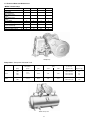
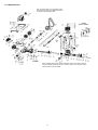
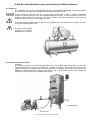
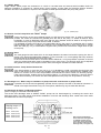
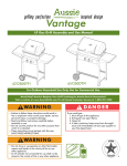
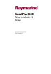
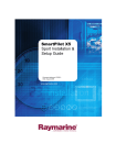
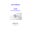
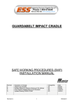
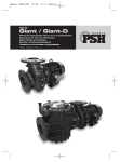
Operating Instructions
Spare Parts List
SPECK “BÜFFEL” Pumps and Pump Units
BS15, BS25, BS40, BS50
1. In General
Every individual pump undergoes a lengthy test-run before leaving our factory. The assembled pump units comply with
the EC guidelines for machinery, 89/329/EEC, Annex II, A.
1.1 Application
SPECK piston pumps are for pumping drinking-water and domestic water and find their use in:
• Single & Multi-storey Houses • Agriculture/Farming • Shipping • Industry • Horticulture
Standard piston pumps and pump units are not to be used for conveying any medium other than water, except if
written consent is given by the manufacturer. Special versions are built by us for pumping other media.
1.2 Economy
Speck piston pumps save energy. They only require 0.25 kW/h to pump 1 m3 of water. The comparatively high price of
a piston pump is rewarded in time by its low power consumption and long working life.
1.3 Accessories
A belt-guard is available for V-belt drive. The law on technical appliances obligates the manufacturer to always supply
a belt-guard, even for pumps without motors. Please note this when ordering.
Declaration of Conformity
Declaration by the Manufacturer
We herewith declare on our own liability
that the following pump units
Pumps with Motor:
that the following
Pump units
BS15
BS25
BS40
BS50
BS15/150L
BS15/200L
BS15/300L
BS25/200L
BS25/300L
Pumps without Motor:
BS15
BS25
BS40
BS50
Pressure Tank
Pressure Tank
Pressure Tank
Pressure Tank
Pressure Tank
comply with pertinent stipulations as per:
EC-Machine Guidelines 98/37/EG
Applied compatible standards:
EN 809
EN 292 T1
EN 292 T2
Electromagnetic Compatibility: 89/336/EWG
Applied compatible standards:
EN50 081-1
EN50 082-2
Use of Electrical Equipment within specified
Voltage Limits: 73/23/EWG
Applied compatible standards:
EN60 335-1
EN60 335-2-51
ppa. ........................................
(Technical Director)
Country of Origin: Federal Republic of Germany
S P E C K - K O L B E N P U M P E N FA B R I K
Otto Speck GmbH & Co. KG · P.O.Box 1240 · D-82523 Geretsried
Tel. (08171) 62930 · Telefax (08171) 629399
D1620 0 1108L
1
1.4 Technical Data and Dimensions
“Büffel” Piston Pump
Model
Flow Rate
Water Head
normal/maximum
Motor Performance
at 40m
Motor Performance
at 60m
No. of V-Belts
Profile x Inner Length
Connection Sizes
Suction x Discharge
Dimensions approx.
Weight w/o Motor approx.
BS15
BS25
BS40
BS50
l/h
1500
2500
4000
5000
m
40/60
40/60
40/60
40/60
kW
0,37
0,55
0,75
1,1
kW
0,55
0,75
1,1
1,5
2
10x820
2
13x975
2
13x1120
2
17x1335
Inch
1x1
1¼x1
1½x1¼
2x1½
cm
kg
52x22x32
28
66x23x38
46
75x26x42
66
85x36x47
90
“Büffelpump”
Pump Units - Pump with Horizontal Tank
Pump Model
Size of Tank
Connection Sizes
Suct./Disch.
Flow Rate
(litre)
(inch)
(l/h)
4 bar
6 bar
1500
0,37
0,55
150
BS15
200
300
BS25
200
300
1x1
1¼x1
1¼x1
Motor Performance
(kW)
2500
0,55
“Büffel“ Pump Unit
2
0,75
Dimensions
(L x B x H)
Weight
(approx. cm)
(approx. kg)
105 x 45 x 84
75
107 x 50 x 85
87
140 x 55 x 96
93
107 x 50x 100
105
140 x 55 x 110
110
1.5 Spare Parts Section
1.51 Spare Parts List
Part No.
Description
BS15
BS25
BS40
BS50
Part No.
1
Crankcase
01.0020
01.0148
01.0149
01.0142
18
Pump V-belt Pulley
1a
Hexagon Screw
21.0290
21.0256
21.0125
21.0258
18a
Hexagon Screw w/Pointed Extension
21.0161
1b
Stud Bolt
21.0147
21.0045
21.0154
18b
Motor V-Belt Pulley
19.0051
1c
Hexagon Nut
07.3001
07.2398
07.0988
18c
Pointed Threaded Stud
2
Gear Cover
03.0012
03.0025
19
Motor Mounting Rail left
2a
Hexagon Screw
21.0256
21.0257
192
2x
Gasket for Gear Cover
06.0440
06.0441
19a
2b
Vent Plug
07.0614
2xx
Gasket for 2b
06.0312
3
03.0026
03.0027
21.0258
06.0442
06.0443
Description
BS15
BS25
BS40
BS50
19.0001
19.0014
19.0008
19.0049
19.0038
21.0113
19.0009
21.0114
23.0001
23.0018
23.0016
Motor Mounting Rail right
23.0119
23.0018
23.0120
Hinge Pin with Thread
11.0332
11.0331
11.0334
19b
Hinge Pin
11.0235
11.0082
11.0335
19c
Hexagon Screw
21.0116
21.0115
21.0120
Insulation Sleeve
07.0161
07.0162
07.2398
Valve Casing Assy w/Stud Bolts + Nuts
00.2384
00.2385
00.2386
00.2387
19d
3a
Suction Flange
20.0031
20.0069
20.0062
20.0087
19e
Hexagon Nut
07.3001
3b
Discharge Flange
20.0031
20.0032
20.0088
191
Hexagon Screw
21.0290
3c
Hexagon Screw
21.0062
21.0188
21.0253
Motor Rocker Assy
00.2442
3x
Flange Gasket
06.0387
06.0400
06.0413
20/21
400
21.0110
19.0050
21.0256
00.2035
Diaphragm Safety Valve Assy w/Seat 4 bar
00.1303
Diaphragm Safety Valve Assy w/ Seat 6 bar
00.1304
Gear Assy
00.2012
00.2013
00.2014
00.2015
20/21
Air Chamber w/Safety Valve 4 bar + Filler Plug
00.2396
00.2397
00.2400
00.2401
20x
Gasket for Safety Valve Casing
00.2443
00.2444
00.1305
00.1306
06.0647
Air Chamber w/Safety Valve 6 bar + Filler Plug
00.2425
00.2426
00.2428
00.2429
21
Safety Valve Seat Assy
00.3205
5
Air Chamber w/o Safety Valve
01.0341
01.0232
01.0235
01.0237
21x
Gasket for No 21
06.0312
00.3208
5x
Air Chamber Gasket
06.0085
06.0086
06.0088
06.0089
22
Acorn Nut for Air Chamber
07.0485
07.1257
01.0021
01.0233
01.0066
01.0534
22a
Air Chamber Stud Bolt
21.0044
21.0195
22b
Disc
07.1259
07.1211
06.1020
07.0485
6
Stuffing Box Casing
6a
Stuffing Box Screw
6b
Seal Ring
6c
Stuffing Box Insert
6d
Gland Packing-Ring
06.1089
6f
Brass Disc
07.1286
6x
Stuffing Box Gasket
06.0508
06.0509
06.0510
06.0220
24x
Gasket
Stuffing Box complete
00.2255
00.2256
00.2257
00.2258
25
Main Bearing Sleeve
05.0032
05.0033
05.0039
05.0034
Piston Rod Assy with Hexagon Nuts
00.2391
00.5414
00.2393
00.2394
26
Oil Splash Cap
03.0100
03.0118
03.0098
03.0167
7
Piston Rod
11.0232
11.0233
11.0029
11.0234
27
Oil Scraper
06.0408
06.0417
06.0470
7a
Hexagon Nut
07.0988
07.1738
28
Oil Filler Plug w/o Thread
07.0489
07.1319
07.1320
29
Snifting Valve G3/8 with Stop Screw
07.2875
07.1291
06.0403
-
-
07.2398
23
Crosshead
17.0014
17.0015
17.0017
17.0002
07.2226
23a
Crosshead Pin
11.0357
11.0358
11.0359
11.0360
06.1136
06.1139
24
Oil Indicator with Nut
-
00.1953
-
-
07.1293
07.2227
00.1959
-
DUO-Piston Simrit
Hexagon Nut
9
Cylinder Assy
00.1916
9a
Hexagon Screw
21.0256
9x
Cylinder Gasket
06.0777
06.0117
06.0525
10
Cylinder Cover
03.0014
03.0040
03.0144
03.0145
10a
Hexagon Screw
21.0366
21.0256
10x
Gasket for Cylinder Cover
06.0589
06.0590
06.0591
11
Suction Valve Assy
00.2170
00.2071
00.1291
111
Suction Valve Stem
112
Suction Valve Seat (Brass)
118
Self-Locking Hexagon Nut
12
Discharge Valve Assy
Discharge Valve Stem
122
Discharge Valve Seat (Brass)
06.0872
06.0419
07.1292
8
07.4083
00.1917
06.0871
06.0877
07.4084
07.1944
00.1918
00.1919
21.0257
07.0023
00.2072
07.0020
06.0312
00.1939
00.1940
29a
Snifting Valve Lip
06.0398
21.0258
29x
Gasket for Snifting Valve
06.0118
30
Bearing Cover open
03.0185
03.0184
03.0028
30a
Bearing Cover closed
03.0013
03.0194
03.0182
30b
Hexagon Screw
06.0119
30x
Gasket for Bearing Cover
06.0447
00.2269
301
Radial Shaft Seal
06.0418
302
Grooved Ball Bearing
05.0111
06.1020
21.0315
07.1945
303
Spacer Ring
07.1302
-
-
304
Spacer Ring
07.1302
00.2270
304a
Woodruff Key
00.1292
07.1219
07.0022
-
07.0065
07.2540
00.1938
Snifting Valve G3/8 with Hose Nipple
07.1220
07.0669
00.2171
Oil Level Gauge/Oil Dipstick
21.0366
07.2539
07.0021
21.0043
07.1259
06.0411
8a
121
06.0873
21.0042
21.0125
06.0448
06.0449
06.0399
05.0151
06.0409
05.0110
07.1307
07.1307
05.0156
07.1321
07.1450
07.1540
07.1200
33
Plug
07.0751
07.2803
07.2608
07.1946
33x
Gasket
06.0312
-
-
34
V-Belt
07.1303
07.1308
07.1312
07.1322
06.0857
06.0858
35
Main Bearing Shaft
11.0018
11.0019
11.0013
11.0014
03.0188
03.0189
-
-
07.1977
06.0746
06.0747
06.0436
07.2538
06.1020
119/129
Suction and Discharge Valve Retainer
113/123
Suction / Discharge Rubber Valve Plate
114/124
Spring Tension Disc (large)
-
-
07.1939
07.1361
35a
Cover for Main Bearing Shaft
115/125
Valve Spring
-
-
07.3662
07.0025
35b
Notched Nail
116/126
Spring Tension Disc (small)
-
-
35x
Gasket for Main Bearing Shaft
117/127
Cotter Pin
-
-
405
Fitting Disc for Connecting Rod 0.5mm
07.1304
07.1313
11x/12x
Gasket for Valve Seat
06.0391
06.0405
06.0416
06.0518
405a
Fitting Disc for Cnnecting Rod 0.2mm
07.1305
07.1314
07.1924
13
Valve Bridge Stud Bolt
21.0002
21.0194
21.0046
21.0051
xx
00.2455
00.2456
13a
Hexagon Nut
07.3001
13b
Disc
07.2904
14
Valve Brigde
15
Plug
07.0487
15x
Gasket
06.0054
06.1065
06.1066
07.1360
07.1215
07.2398
-
03.0268
07.0988
-
-
03.0042
03.0044
Complete Set of Gaskets
00.2453
00.2454
03.0190
Crankcase Assy
00.2753
00.2754
00.2755
00.2756
Crankcase Assy, exchanged
00.2757
00.2758
00.2759
00.2760
Pump Head Assy with Safety Valve 4bar 00.2617
00.2618
00.2619
00.2620
Pump Head Assy with Safety Valve 6bar 00.2745
00.2746
00.2747
00.2748
16
Plug
07.0487
Air Volume Control
00.2479
16x
Gasket
06.0054
Air Hose 0.9 m
32.0006
17
Connecting Rod Assy
17a
Tension Screw for Connecting Rod
17b
Sleeve for Connecting Rod
17c
Hexagon Nut
00.2004
00.2005
21.0103
05.0066
05.0067
07.2618
00.2006
00.2007
Drain Cock G3/8
00.1940
21.0104
21.0105
Gasket for Drain Cock
06.1020
05.0068
05.0069
07.2022
07.1995
3
07.1925
1.5.2 Exploded View
N.B. The self-locking nut in the suction valve
should only be used once.Please keep this in
mind when ordering spare parts!
Valves
BS15 / BS25
When ordering spare parts, please state item number and code number of
the part required as well as the pump model and year of construction which
can be found on the name plate.
4
2. Safety
This Operation Manual gives basic instructions which are to be observed during installation, operation and
maintenance of the pump. It is therefore imperative that this manual be read by the responsible personnel/operator
prior to assembly and commissioning. It is always to be kept available at the installation site. It is not only the general
safety instructions contained under this main heading `Safety` that are to be observed, but also the specific
information provided under the other main headings.
2.1 Kennzeichnung von Hinweisen in der Betriebsanleitung
Safety instructions given in this manual, non-compliance with which would affect safety,
are identified by the following symbol:
or where electrical safety is involved, with
see DIN 4844 - W9
see DIN 4844 - W8
Safety measures which can cause damage to the machine if not adhered to, are marked
It is imperative that signs affixed to the machine, e.g.
• arrow indicating the direction of rotation
• symbols indicating fluid connections
be observed and kept legible.
2.2 Qualification and Training of Operating Personnel
The personnel responsible for operation, maintenance, inspection and assembly must be adequately qualified. Scope
of responsibility and supervision of the personnel must be exactly defined by the plant operator. If the staff does not
have the necessary knowledge, they must be trained and instructed, which may be performed by the machine
manufacturer or supplier on behalf of the plant operator. Moreover, the plant operator is to make sure that the contents
of the operating manual are fully understood by the personnel.
2.3 Hazards in the Event of Non-Compliance with the Safety Instructions.
Non-compliance with the safety instructions may produce a risk to the personnel as well as to the environment and the
machine, and may result in a loss of any right to claim damages.
For example, non-compliance may involve the following hazards:
• Failure of important functions of the machine/plant
• Failure of specified procedures of maintenance and repair
• Exposure of people to electrical, mechanical and chemical hazards
• Endangering the environment owing to hazardous substances being released.
2.4 Safety at Work
The safety instructions contained in this manual, the relevant national accident prevention regulations and any other
service and safety instructions issued by the plant operator are to be observed.
2.5 Safety Instructions Relevant for Operation
• If hot or cold machine components involve hazards, they must be guarded against accidental contact.
• Guards for moving parts (e.g. coupling) must not be removed from the machine while in operation.
• Any leakage of hazardous (e.g. explosive, toxic, hot) fluids (e.g. from the shaft seal) must be drained away so as to
prevent any risk to persons or the environment. Statutory regulations are to be complied with.
• Hazards resulting from electricity are to be prevented (see, for example, the VDE Specifications and the by-laws of
the local power supply utilities).
2.6 Safety Instructions Relevant for Maintenance, Inspection and Assembly Work
It shall be the plant operator’s responsibility to ensure that all maintenance, inspection and assembly work is
performed by authorized and qualified personnel who have adequately familiarized themselves with the subject matter
by studying this manual in detail.
Any work on the machine shall only be performed when it is at a standstill.
Pumps and pump units which convey hazardous media must be decontaminated.
On completion of work, all safety and protective facilities must be re-installed and made operative again.
Prior to restarting the machine, the instructions listed under `Operation` are to be observed.
5
2.7 Unauthorized Alterations and Production of Spare Parts
Any modification to the machine may only be made after consultation with the manufacturer. Using spare parts and
accessories authorized by the manufacturer is in the interest of safety. Use of other parts may exempt the
manufacturer from any liability.
2.8 Unauthorized Modes of Operation
The reliability of the machine delivered will be only guaranteed if it is used in the manner intended, in accordance with
clause 1 `In General` of this manual. The limit values specified in the data sheet must under no circumstances be
exceeded.
Pending Standards and other Data
DIN4844 Part 1:
Safety descriptions and safety signs W8 supplement sheet 13
DIN4844 Part 1:
Safety descriptions and safety signs W9 supplement sheet 14
3. Transport and Storage
Pumps and pump units must not be stored for any length of time in a humid place or where temperatures are below
zero.The storage room should be airy as moisture will damage the motor and thus void the warranty.
Pumps are packed for transportation in cardboard boxes or on pallets. When unpacking, check for damage.
4. Description
4.1 “Pumpmeister”
SPECK piston pumps of the ‘’Büffel’’ pump series have a thoroughly proven double-helical precision gear of
unsurpassed working quietness and service life.
When turned in the correct direction, the gear is lubricated by an oil-dip bath with flooded crosshead. Suction and
discharge connections are on the valve casing and are interchangeable.
Valve casing, air chamber, stuffing box and cylinder cover are of grey cast iron (GG20).
The brass suction and discharge valves (2 of each) are made easily accessible by removing the air chamber. The
suction/discharge line does not have to be removed. The solid conrod is of bronze (G-CuSn10). The brass cylinder
sleeve can be removed using set-screws. The duo-piston is of NBR rubber. Teflon-impregnated packing rings are
used for the piston rod sealing in the stuffing box.
A built-in diaphragm safety valve protects against excess pressure. Water will not flow out of the pump if the pressure
is too high. Surplus water is circulated within the pump, back to the suction side.
4.2 “Büffelpumpe” Pump Unit
SPECK pump units are ‘’Büffelpumpe’’ piston pumps on galvanized horizontal pressure tanks, complete systems
ready for connection. They are equipped with an electric motor, V-belt pulleys, V-belts, belt-guard, automatic air
volume control, pressure switch, pressure gauge and a built-in safety valve.
The automatic air volume control installed in the pressure tank of the unit automatically ensures the correct ratio
between water content and the necessary air cushion.
If the horizontal tank is half full, the valve of the automatic air volume control, activated by the float, opens and the
pump begins conveying both air and water into the tank.
A suction head of approx. 4-6 m is required so that the pump can draw in air in the proper manner.
When water leaves the tank, the pressure in the tank drops until the pressure eventually sinks to the automatic switchon point at which the pressure switch turns on the motor/pump. The amount of water which left the tank is then
pumped in again until the switch-off level is attained. This procedure repeats itself again and again at irregular
intervals, depending on how often and how much water is withdrawn from the tank.
4.3 Values for Pressure Switch Adjustment
Pump Unit 4 bar:
Switch-On Pressure:
Switch-Off Pressure:
2 bar
3.5 bar
Pump Unit 6 bar
Switch-On Pressure:
Switch-Off Pressure:
3 bar
5.5 bar
6
5. Set-Up and Installation (only to be done by skilled workmen)
5.1 Pump Unit
The complete pump unit with horizontal pressure tank is supplied ready-assembled. A special foundation
is not necessary. The tank can be fixed to the foundation by 4 spacer blocks.
The room must be frost-proof and dry. It should also be well aired in order to prevent undesirable
moisture condensate forming on the unit. Moisture damages the motor. If there is a danger of frost, the
drainage plugs (15) are to be removed. The piston chamber must then be emptied by closing off the
suction line and running the pump for approx. 30 sec.
To protect against accidents, each pump is to be equipped with a belt-guard which conforms to trade
union and/or general safety rules.
The pump-motor must be
protected by a correctly
adjusted motor protector.
„Büffel“ Pump Unit: Pump and motor,
horizontal pressure tank and belt-guard
5.2 Pump Unit with Vertical Tank
Assembly:
In contrast to the pump units with horizontal tanks which are supplied ready assembled, the units with
vertical tanks have to be set up and installed by a plumber on location. They function the same as the
ready assembled units. However, we wish to point out that an automatic air volume control can also be
installed in a vertical tank when the unit is being set up (s. fig. 113). Directions (D10671) for installing the
automatic air volume control are available upon request.
Discharge Line
Suction Line
Fig. 113 „Büffel“ pump
7 unit with vertical tank
5.3 „Büffel“ Pump
Single ‘’Büffel’’ piston pumps are screwed on to a brick or concrete base and secured with foundation bolts. No
particular foundation is required for vertical tanks. Pumps without a base plate and therefore without vibration
insulation should be mounted on to a piece of anti-vibration material placed between the pump and ground.
Fig. 112 „Büffel“ pump
5.4 Suction Line for Pump Units and ‘’Büffel’’ Pumps
Perfect functioning of the pump depends largely on well layed-out suction lines. In order to prevent airpockets, the suction line should rise gradually from the well to the pump, or should at least be layed
horizontally. It must be absolutely seal proof and the inner diameter should at least be as large as the
connection on the pump. Only bows are to be used, no elbows.
It is advisable to install a foot valve or an intermediate valve in the case of a closed filter well. If suction
lines are longer than 30 m, a suction air chamber is to be installed directly in front of the pump. If vertical
tanks are used (fig. 113), it is advisable to support heavy suction lines so that their weight does not pull
on the pump.
5.5 Suction Head
The total gauged suction head which is the height between the water level and the pump plus loss of
friction in the pipe and possible filter resistance, is not to exceed 7.5 m, not forgetting that in dry seasons
the water level in the well may be lower than usual.
In the case of short suction lines or a suction head of below 2m, or if input pressure is present, a shut-off
valve (not a tilted seat-valve) must be installed in front of the pump. This shut-off valve can be adjusted
with greater accuracy to the required suction head, ensuring the avoidance of water-hammer.
5.6 Intake Pressure - Pump Unit as Booster Set
If the inlet pressure is more than 0.3 bar (3 m), it is advisable to install a pressure-free tank with float
valve. If this cannot be done, a shut-off regulator valve must under all circumstances be installed in the
feed line. A vacuum of 4-6 m has to be provided if the automatic air volume control is to function properly.
If the pump hammers, install a suction air chamber (approx. 7.5-15 ltrs) in the feed line. A shut-off valve is
at all events necessary in a suction line with intake pressure so the pump can be opened for servicing.
5.7 Discharge Line - Refers only to installation of pump units with vertical tanks or pumps alone
If possible, the line should rise gradually upwards from the pump to the tank or at least be horizontal - it
should never slope downwards. Only use curved joints, elbows may only be used after the tank.
5.8 Umtausch der Saug- und Druckanschlüsse
(Does not apply to units with horizontal tanks)
The suction and discharge sides of SPECK ‘’Büffel’’ pumps can be interchanged by converting the suction and
discharge valves. This often saves inconvenient installation of suction and discharge lines. Install clean valve seals
and make sure the valves sit properly.
Starting torque of
holding screw:
BS15: 12Nm (M8)
BS25: 16Nm (M10)
BS40: 18Nm (M10)
BS50: 36Nm (M12)
After suction and discharge
valves have been exchnged, the
air chamber must be turned
around 180° so that the safety
valve is always located on the
discharge side. ( see figure 115)
Fig. 114
8
6. Operation
6.1 To Fill Pump with Oil
Fill crankcase with an SAE30 quality oil through opening above crosshead (23).
BS15
BS25
BS40
BS50
0,2 litres
0,3 litres
0,8 litres
1,0 litres
6.2 To Fill Pump with Water
Fill up pump head with water by pouring the water in via filler plug (33) At the same time, turn the pump
V-belt pulley (18) manually in the direction of the arrow. In the case of long suction lines, fill right up to the
foot valve/intermediate valve (see 5.4)
6.3 Motor Alignment and Electrical Connection
Using a ruler, make sure the pump pulley and motor V-belt pulley (18/18b) are in line with each other. The
motor could have been shifted during transport and if the pulleys do not align precisely, the belts will wear
out quickly.
Electric motors must be connected as per circuit diagram which can be found in the terminal box of the
electric motor. This work is to be carried out by suitably qualified persons.
6.4 Fittings
Open shut-off fittings and taps in the discharge line so that the air in the pipe system can escape.
6.5 To Switch on Motor
Check the direction of rotation. Reverse polarity if the motor is running in the wrong direction. Close the
shut-off fitting only after water has begun being pumped, after the suction line and pump are vented
(clearly visible through transparent tube – fig. 111/II) and after water has come out of the tap. Depending
on the size of the tank, it takes between 5-15 minutes until the tank is full and the pressure switch
switches off at either 3.5 bar or 5.5 bar.
6.6 To Let Water Out
Turn tap on and let water out. Pressure drops eventually to 2 or 3 bar respectively and the pump switches
on again automatically. Only a few air bubbles should now be visible in the suction line, otherwise there is
reason to believe that the suction is not correctly sealed. Approximately 2000 litres of water per hour flow
out of an open G1/2 tap at 3 bar pressure.
6.7 On/Off Switching Pressure
(for 4 and 6 bar units)
The pump unit has a diaphragm safety valve which is adjusted to an activation pressure of either 4 or 6
bar. The pressure tank is also approved for max. pressure of 4 or 6 bar. The pressure switch must
therefore be adjusted to a maximum pressure of 3.5 bar / 5.5 bar otherwise it will activate the safety
valve. To readjust switch-on / switch-off pressure, see instructions on pressure-switch (Fig. 111/IV).
Switching Stages:
4 bar Pump Unit
6 bar Pump Unit
Switch-On Pressure
Switch-Off Pressure
Switch-On Pressure
Switch-Off Pressure
2 bar
3,5 bar
3 bar
5,5 bar
Suction Line
Discharge Line
Fig. 111 Büffel Pump Unit
9
7. Maintenance and Servicing
7.1 Lubrication
The gear is lubricated automatically provided the pump revolves in the correct direction. Oil level should
be checked every three months and topped up if necessary till oil can be seen through the indicator glass
(24). First oil change after 3 months operation and then every 2 years, or every 6 months if the pump is
running continuously. This is done by unscrewing the indicator (24) or screw (16) and draining out the old
oil. Clean out the crankcase thereafter (removing gear cover [2]) and refill with fresh oil as described
under paragraph 6.1.
7.2 Stuffing Box
The compact stuffing box is made up of Teflon-impregnated packing rings and a seal ring and requires
practically no maintenance at all. The stuffing box must not run dry. Single isolated drops serve to
lubricate and cool it. Should the stuffing box continuously drip, tighten stuffing box nut (6a) carefully by
approx. one 1/2 turn. If this does not help, the whole stuffing box (6d) must be replaced. In this case, the
seal ring (6b) should also be changed. Pay careful attention when installing seal ring: the lip ring spring
must face the piston.
7.3 V-Belts
V-belt (34) should not be overtensioned. However, it is advisable to tighten belts up again after a few
days of operation. When renewing V-belts on multi-belt drive, the complete set has to be replaced.
7.4 Gear
The original SPECK high pressure ‘’Büffel’’ pump has a double-herringbone (helical) precision gear with a
bronze connecting rod. If the directions under paragraph 7.1 for lubrication are followed, further
maintenance is practically unnecessary. Only the connecting rod alone might need readjusting after
approx. 1 year when it has been run in and if a possible knocking sound can be heard. To do this,
unscrew self-locking hexagon nut (17c), screw out inner hexagon tension screw and remove 0.1 - 0.5 mm
of spacer shims (405) as required from connecting rod joint. Screw back tension screw (17a) tightly
against hexagon nut. After approx. 1 hour of operation, check whether the connecting rod has not been
overadjusted and is running hot.
Abb. 115 Crosssectional Diagramm of Casing
7.5 Air Replenishment - for Cold Water Operation Only
The pump will run smoothly and silently if there is air in the air chamber. This air cushion is regulated via
the snifting valve. At the same time air is pumped into the pressure tank. The more air there is in the
pressure tank, the more water can be discharged before the pump switches on again (see paragraph
4.2).
If the automatic air volume control has to be repaired, kindly ask for our instruction sheet D10672. The
unit itself is only available as a complete set.
10
8. Failures and Remedies
If you have trouble with your pump, you may be able to help yourself by reading the tips we give you below. If you cannot
find the reason for the trouble, call a plumber or write to us, not forgetting to mention the pump model and its serial
number.
Prior to doing any work on the pump, switch off the electricity and make sure that the pump is idle
and the pressure at zero.
8.1 Little or no water at all is being pumped
Possible Reason
Remedy
a) Pump is running but delivers no water even though
it is filled properly.
Remove air chamber (5) and loosen rubber valve discs (113/123) which have probably
got stuck if the pump has been stored for a long time.
b) Not sufficient water in the pump.
Refill pump as explained in 6.2 and at the same time turn the pump several times pouring
in water little by little till there are 2-4 litres in the pump. Screw on filler plug (33) again and
seal carefully. More water may be necessary if the suction line is very long or the suction
head very high.
c) Suction head too high / suction line too long.
Measure difference between water level and pump flange connection (fig. 111/I).
Compare loss of friction in long pipes with table (available upon request) and add the
difference in height.
d) Suction line is not seal-proof.
After the pump has been running for a while, check whether air bubbles can be seen
through transparent hose (Fig. 111/II) above elbow on tank. If so, press out air, find leak
and make it seal-proof.
e) Soiled or worn-out valves
Pebbles, hemp, shavings etc. coming from new wells often get absorbed into the pump so
the air chamber (5) has to be removed and the valves checked. Loosen nuts above valve
bridge. Remove valve bridge and any crust which may be on it. Valves are not screwed in.
If they are stuck, press them loose with the handle of a hammer. The valve seat seal is
under the valve - make sure that the seat is clean. Rubber valve discs (113/123) may
have to be replaced if the pump is old.
f) Stuffing box is not seal-proof.
Tighten up nut (6a) a little. If this does not help, replace packing rings (6d) and possibly
seal rings (6b) as well. Do not use hemp, we use Teflon-impregnated packing rings.
8.2 Pump Knocks
Possible Reason
Remedy
a) There is no air cushion in the air chamber
Make sure that the air volume control (Fig.111/III) is working properly. The snifting valve
should hiss when the pump is running. Check whether rubber lip (29a) is dirty or clogged.
Air could be escaping through screw on filler plug, therefore check by covering sealing
surfaces of air chamber and filler plug with a soap solution.
b) Pre-pressure in pump
Water level in pump/air chamber is too high because snifting valve has not absorbed enough
air. Install regulator in suction line (s.5.5/5.6). Pump should run with about 5 metre vacuum
ensuring that sufficient air is pumped.
c) Pump suction head is very low
Same applies here as explained under b). A vacuum must be provided by means of a
regulator so that sufficient air will be pumped.
d) High suction head - long suction line
Install a suction air chamber as per 5.4 and ensure sufficient ventilation. Make sure there
is enough water in the well, e.g. after a dry season.
e) Conrod bearings in pump deflect
You can not always determine the reason for knocking by ear, so you have to turn the Vbelt pulley (18) backwards and forwards to determine any clearance between bearing and
conrod. Repairs to the gear are best done by a skilled tradesman.
f) The pump V-belt pulley deflects and does not sit
properly on the crankshaft
As described under e).
g) One of the ball bearings is defective
As described under e).
8.3 Pump switches on when very little water is discharged and switches off immediately the tap is turned off
Possible Reason
Remedy
The air cushion is not filled up sufficiently. During
initial operation, there may not have been enough air
pumped into the tank or the air the pump has pumped
into the tank is escaping somewhere (pressure
switch, pressure gauge, air volume control, pump
connections, transport damage).
If snifting valve and air volume control are working properly (111/III) and there still is not
enough air in the tank, coat all threaded connections on tank with a soap solution to
determine where it is leaking. It could also be that the pressure switch (111/IV) is not airtight.
11
8.4 Pump switches on automatically although taps are turned off
Possible Reason
Remedy
a) A tap is leaking or air is escaping from the tank.
Check by switching off the complete unit overnight. Turn off all taps and check whether
the pressure drops.
b) Leaky valves or leaky safety valve cause water to
run back into the well.
Open pump and check whether the valves are sealing properly.
c) Foot valve/intermediate valve in the suction line
leaks. Water runs back into the well.
Switch pump off and lift safety valve at 3.5/5.5 bar. If foot valve/intermediate valve is
working properly, no return flow should be heard (or seen at pressure gauge of tank)
immediately after lever (214) has been lifted.
8.5 Air escapes from tap when water is let out
Possible Reason
Remedy
a) There is too much air in the tank. The well water is
probably very gassy and a lot of air separates into the
tank. If the suction line is very long and the suction
head high, it could be that too much air is being
pumped.
In this case, it is advisable to disconnect the pipe of the air volume control for a while or
install a special rubber lip with a very small hole into the snifting valve.
b) Suction line leaks.
Find leak and seal it.
8.6 Water is pumped easily till shortly before switch-off pressure is reached and then the pump continues to
run but does not pump any water because it can’t reach the final pressure
Possible Reason
Remedy
This can happen if too much air is pumped through
the air volume control when suction lines are very
long and suction head very high. This often occurs
when the suction line is not absolutely seal-proof and
allows even more air to get into the pump. It can also
be caused by worn out rubber valve plates, worn out
cylinder or pistons.
We recommend either installing a rubber lip with a very small hole or put the air volume
control in the suction line out of action from time to time.
Replace rubber valve plates (113/123). Check whether piston or brass cylinder are worn
out and replace as necessary.
8.7 Water leaks at Air Volume Control
Possible Reason
Remedy
Rubber lip of snifting valve (29) is damaged.
Replace rubber lip (29a).
Suction Line
Discharge Line
Fig. 111 „Büffel“ Pump Unit
12