1
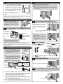
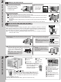
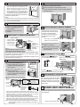
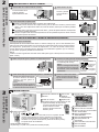
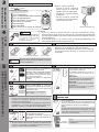
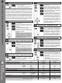
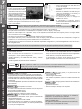
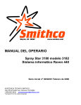
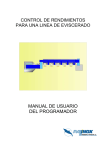
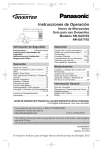
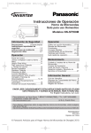
ROOM AIR CONDITIONER
OPERATING INSTRUCTIONS
ENGLISH
MODEL:
CW-XC103VU
CW-XC123VU
Please read these operating instructions thoroughly before using
your air conditioner and keep them for future reference.
For assistance, please call: 1-800-211-PANA (7262) or send e-mail to
[email protected] or refer to www.panasonic.com
F563446
SAFETY PRECAUTIONS
1
Please observe these following safety precautions when using
your air conditioner.
• Failure or negligence in observing these safety precautions
could cause fire, electrical shock or personal injury.
OPERATION PRECAUTIONS
WARNING This sign warns of risk of death or serious injury.
• Do not modify the length of the power cord or use an extension cord.
• Do not touch or operate with wet hands. Do not modify or damage
the cord.
• Do not turn on the unit by inserting the power plug. Do not switch off
the unit by pulling out the power plug.
• Avoid an extended period of direct airflow.
• Do not insert sticks, fingers or other objects into the unit.
• Do not try to repair the unit yourself.
This symbol (with a white background)
denotes an action that is PROHIBITED.
These symbols (with a blue background) denote
actions that are COMPULSORY.
INSTALLATION PRECAUTIONS
• Plug in properly before operating and use a specified power cord.
• If abnormal conditions (burnt smell, etc) occur, switch off and remove
the power plug.
• Due to the weight of this product, we recommend that
you have a helper to assist in the installation. To avoid
injury, use the proper method of lifting. Avoid any sharp
edges.
• Make sure the window frame to be used can
properly support this product.
• This product must be installed in accordance with all local
codes and ordinances.
• Do not install the unit in places where inflammable gas,
fumes or soot may be generated.
CAUTION This sign warns of injury or damage to property.
•
•
•
•
•
•
Do not use the unit for other purposes, than its intended use.
Do not remove the power plug by pulling the cord.
Do not block the air intake and outlet vanes.
Do not splash or direct water at the unit
Do not expose the unit to direct sunlight during operation.
Do not operate the unit without the air filter installed or when the front
intake grille has been removed.
• Do not place any objects on the unit.
• Do not operate any combustion equipment near the unit’s airflow area.
OPERATION PRECAUTIONS
• Operate your air conditioner from a stable 115 volt AC
supply.
• Plug into a separate 15 amp grounded outlet only.
• Use of extension cords
Avoid using extension cords. If there are no alternatives,
ensure that the cord is a UL listed 3-wire grounding type,
rated 125 volts with a minimum current-carrying rating of
15 amps, number 14 or heavier wire.
• Use a 15 amp time delay fuse or a circuit breaker.
• Do not switch off by unplugging the power plug while it is
operating. Press the OFF/ON pad to “OFF” before
unplugging.
AIR CONDITIONER INSTALLATION
2
• Switch off the breaker and remove the power plug from the socket if
the unit will not be operated for a long period.
• Pay attention to any damages on the unit caused by extensive usage.
• Ventilate the room occasionally where the unit is installed.
• Remove the power plug when cleaning the unit.
POWER SUPPLY
Time Delay Fuse : 15 Amps
Rated Voltage : 115V
• Line Cord Plug
• Socket Type
INSTALLATION BOX CONTENTS
Sealer 50 g
(1.8 oz) (Putty)
SCREW FURNISHED
Top sealing
ribbon
Window sash
sealing ribbon
Side
sealing
ribbon
Window sash
foam seal
Type A
screw
Top
angle
Type A
screws
Type A
(Qty 6)
Type B
(Qty 5)
Type C
(Qty 6)
Wood
Screw
Machine
Screw
Tapping
Screw
SUGGESTED TOOL LIST
Type C screws
Medium sized
screwdriver (#2
Phillips)
Type C screws
Tape Measure
Type A screw
Right side
expandable
panel
Left side
expandable panel
Pencil
Level
Type B screws
Knife or
Scissor
Type A screws
ACCESSORIES
SELECT THE BEST LOCATION
(6 pcs)
(XTN5D25A)
(5 pcs)
(CWH4580211)
(Single or Double
hung window)
Window
19–3/16 inches
12 inches
Front grille
(6 pcs)
(XTT4D10C)
NOTE
Check that none of the accessories are missing.
SIDE VIEW
More than
4 inches
WINDOW REQUIREMENTS
CHASSIS INSTALLATION INTO THE CABINET
15-15/16” (min)
• Hot sun rays hitting the outside surface
of the cabinet will create considerable
heat load. If the outside of the cabinet is
exposed to direct sunlight, consider
building an awning to shade the cabinet
22 to 42-1/8”
while providing ample area for the heated
air to be exhausted from the condenser
(both sides) and the top.
This unit is designed for installation in
standard double hung windows.
NOTE
The unit may also be installed “through the wall”. You should,
however, observe standard carpentry practices and frame the
opening without violating local ordinances.
1 Slide the chassis into the cabinet.
2 Reinstall the cabinet screws.
Secure the cabinet to chassis by using screws (from
rear cabinet).
°F
hr
TIMER
TEMP/TIMER
FAN
OPERATION
SET
SET/
CANCEL
COOL
OFF/ON
MODE
AIR SWING
HIGH
MED
LOW
ECONOMY
FAN SPEED
Wireles
Remot
s
e Cont
r ol
INSTALLATION PROCEDURES
1 Remove the rear cabinet
INSTALLATION OF THE FRONT GRILLE
screws and save for later use.
2 Slide the chassis out from the
cabinet.
°F
hr
TIMER
TEMP/TIMER
FAN
OPERATION
SET
SET/
CANCEL
COOL
OFF/ON
MODE
AIR SWING
HIGH
MED
LOW
ECONOMY
FAN SPEED
Wireless
Remo
te Con
tro
l
HOW TO ASSEMBLE THE EXPANDABLE PANELS
Depending upon the location
of the AC outlet, route the AC
cord to either the left or right
side while installing the front
grille.
°F
TIMER
OPERATION
TEMP/TIMER
hr
SET
OFF/ON
SET/
CANCEL
COOL
FAN
MODE
AIR SWING
HIGH
MED
LOW
ECONOMY
FAN SPEED
Wireles
s
Control
Remote
Top angle
Top sealing
ribbon (To be
attached to the
top angle)
This figure shows the AC cord
routed to the left side.
Expandable panel
1 Place the front grille on the
Side sealing ribbon
(To be attached to
the expandable
panel)
Type B screws
NOTE
This procedure applies to left and right
of assembling expandable panel.
cabinet first.
2 Secure the front grille to the
°F
TIMER
hr
main chassis using screw
provided.
OPERATION
TEMP/TIMER
SET
OFF/ON
SET/
CANCEL
COOL
FAN
MODE
AIR SWING
HIGH
MED
LOW
ECONOMY
FAN SPEED
Wireles
Remo
s
te Con
trol
Type C screws
• Attach the top angle to the cabinet using screw type B (3 pcs).
• Insert expandable panels to cabinet sides as shown.
• Secure the first fold of expansion panel to cabinet using screw
type C (3 each).
INSERT THE
Attach the
(part no.
CZ-SF6P) to the frame.
Slot in the
and the
frame (part no. CZ-SFW6P) to
the front grille.
CABINET INSTALLATION
1 Cut the “Sealing Ribbon” to the
proper length, and attach it along
the bottom edge of the bottom
window sash.
Window sash
sealing ribbon
2 To prevent condensation water
°F
TIMER
OPERATION
TEMP/TIMER
hr
SET
OFF/ON
SET/
CANCEL
COOL
FAN
MODE
AIR SWING
ECONOMY
HIGH
MED
FAN SPEED
LOW
Wireless
Remot
e Co n t
ro
l
The
and the frame can be obtained separately
from your nearest servicenter.
from dripping inside, the cabinet
should be installed level or very
slightly tilted to the outside.
INSERT THE AIR FILTER
3 Secure the cabinet using screws.
Type A
screw
Inside of
sash
Type B
screws
Top angle
Outside of sash
Window sash
Sealing ribbon
Attach the air filter to the intake grille
°F
hr
TIMER
OPERATION
TEMP/TIMER
SET
OFF/ON
SET/
CANCEL
COOL
FAN
MODE
AIR SWING
ECONOMY
HIGH
MED
LOW
FAN SPEED
Wireless
Control
Remote
Expandable panel
Window sill
Type A
screws
Window sash
foam seal
• Expand the expandable panel fully into the grooves of the
window frame, secure the expandable panel, left, right and
top mounting frames to the bottom of the window sash
using 4 screws type A and 2 screws type B.
• Secure the cabinet using wood screws type A.
• Cut the window sash foam seal to the proper size and
seal the opening between the top of the inside window
sash and the outside window sash.
Note : If a gap exists between the unit and window sash, you may
use “Sealer” supplied with the installation kit for a better seal.
PLACE FRONT INTAKE GRILLE OVER THE FRONT GRILLE
Slide the front intake grille slightly to the right to reattach the
tabs and then push it down to close tight.
°F
hr
TIMER
TEMP/TIMER
OPERATION
SET
SET/
CANCEL
OFF/ON
COOL
FAN
MODE
AIR SWING
ECONOMY
HIGH
MED
LOW
FAN SPEED
Wireles
Remote
Lift up about 90°.
s
Control
AIR CONDITIONER INSTALLATION
2
REMOVAL OF FRONT GRILLE
2 Remove the air filter.
1 Remove the front intake grille.
Pull up the front intake
grille about 90° and slide
it slightly to the left to
unhook the tabs.
°F
hr
TIMER
TEMP/TIMER
Tilt up and pull
out the air filter
by the holder.
OPERATION
SET
SET/
CANCEL
OFF/ON
COOL
FAN
Air filter
°F
LOW
TIMER
FAN
ECONOMY
OFF/ON
MODE
AIR SWING
FAN SPEED
ECONOMY
HIGH
Wireless
MED
R em ote
LOW
Control
FAN SPEED
Wireless
Remote
a
the adhesive tape from all sides of the front grille.
b Remove
At bottom right side of the front grille, press inward on cabinet near the power cord, and pull
grille outward to the right until right tab releases.
c the
At the bottom left side, push inward on cabinet and pull the grille outward to the left to release
the left tab.
a
c
Do not pull the bottom edge toward you more than 3 inches to prevent the two top tabs from
damage.
Slide the front grille upwards to free the two top tabs from slots at the top of the cabinet.
Control
d
3 Remove the front grille.
d
OPERATION
SET
SET/
CANCEL
COOL
AIR SWING
MED
TEMP/TIMER
hr
MODE
HIGH
°F
hr
TIMER
TEMP/TIMER
FAN
OPERATION
SET
SET/
CANCEL
COOL
OFF/ON
MODE
AIR SWING
HIGH
MED
LOW
ECONOMY
FAN SPEED
Wireless
Remote
Control
b
HOW TO ATTACH THE DRAIN PAN (OPTIONAL)
Condensed water drainage
This air conditioner employs a “Slinger-Up System” which is designed to splash the condensed
water on the condenser coil for maximum cooling efficiency, thus producing a splashing sound.
If the splashing sound annoys you, you can provide an outside drainage by using the following
procedure which may, however, cause a small loss of performance.
Note: The cabinet should be installed tilted slightly lower to the rear for necessary condensate
drainage. (Max. 13/32”)
Maximum
13/32”
Condensed water
1 Remove the rubber plug and slide the chassis out from
3 Connect a drain hose (optional).
the cabinet.
Fit the drain hose to the drain pan.
Note
Drain hose or tubing can be
purchased locally to satisfy your
particular needs.
OPERATION
TIMER
°F
TEMP/TIMER
hr
SET
SET/
CANCEL
OFF/ON
ECONOMY
AIR SWING
COOL
MODE
FAN
HIGH
MED FAN
SPEED
s
Wireles
Control
Remote
LOW
Install the drain pan at the right
corner of the cabinet using 2
screws (part no. CWG86C733).
4 Slide the chassis back into the
INTERNAL VIEW
Note
The drain pan (part no. Screws
CWH40175) can be obtained Drain pan (optional)
from nearest servicenter.
PART IDENTIFICATION
3
Drain hose
(not included)
Under-side view with drain
pan and hose in place.
Remove the
rubber plug
2 Install the optional drain pan (part no. CWH40175).
EXTERNAL VIEW
cabinet.
Reinstall the cabinet screws.
Secure the cabinet to chassis by
using screws.
°F
hr
TIMER
TEMP/TIMER
FAN
OPERATION
SET
SET/
CANCEL
COOL
OFF/ON
MODE
AIR SWING
HIGH
MED
LOW
ECONOMY
FAN SPEED
Wireless
Remo
te Con
tro
l
MAIN UNIT
1
1 Air inlet louver
2 Cabinet
2
6
7
4
8
5
9
3
4 Air filter
5 Front intake
grille
3 Power cord
6 Front grille
7 Vertical airflow direction vane
(Airflow direction adjustment up-down).
The vertical airflow direction
vane is controlled by
rotating the horizontal vane
forward or backward.
8 Ventilation lever
°F
hr
TIMER
TEMP/TIME
R
FAN
AIR SWING
MED
LOW
ECONOMY
FAN SPEED
Wireless
Remote
hr
TIMER
TEMP/TI
MER
FAN
ION
SET
SET/
CANCEL
COOL
OPERAT
OFF/ON
MODE
AIR SWING
HIGH
MED
LOW
ECONO
FAN SPEED
Wireless
Remot
e Contro
l
MY
The ventilation lever must be in the CLOSE position in order
to maintain the best cooling conditions. When fresh air is
necessary in the room, set the ventilation lever to the OPEN
position. The damper is opened and room air is drawn out.
TYPES OF SIGNAL SOUND
One long “Beep” and one short “Beep”. (Sound from the main unit.)
OFF/ON
MODE
HIGH
°F
OPERATION
SET
SET/
CANCEL
COOL
9 Touch control panel
e
d
TEMP/TIMER
hr
b
COOL
FAN
MODE
a
b
c
d
Control
e
f
g
h
i
MED
LOW
SET
SET/
CANCEL
AIR SWING
OFF/ON
g
f
ECONOMY
h
HIGH
c
OPERATION
TIMER
°F
a
FAN SPEED
i
Wireless
Remote Control
Display Panel
MODE selection pad
FAN SPEED selection pad
TEMPERATURE/TIMER
setting pad
TIMER pad
Timer SET/CANCEL pad
OPERATION OFF/ON pad
AIR SWING pad
ECONOMY pad
PART
IDENTIFICATION
3
ACCESSORIES
• Remote control
•
and frame
1
2
3
4
5
6
7
8
9
Signal Transmitter
OPERATION button
TEMPERATURE/TIMER setting button
TIMER button
TIMER SET/CANCEL button
MODE selection button
ECONOMY Button
AIR SWING button
Fan Speed Selection Button
PREPARATION BEFORE
OPERATING
WARNING
Ensure that the power
plug is securely inserted.
A loose plug may cause a
fire or an electric shock.
1
2
OPERATION
3
TEMP/TIMER
TIMER
SET/
CANCEL
4
6
5
7
MODE
ECONOMY
AIR SWING
FAN SPEED
8
Panasonic
9
1
2
Insert the two batteries.
Open the cover.
CAUTION
°F
°F
hr
OPERATION
3
Start operation by pressing
OPERATION.
The operation will turn on and the
display panel will light up.
To stop the operation, press the
OPERATION again.
The unit will stop operating and the
display panel light will turn off.
•
•
•
Wireles
Remote
s
Control
SELECTING OPERATION MODE
HIGH
MED
FAN SPEED
LOW
COOL
FAN
Press TEMP/TIMER ▲ or ▼ to set the
display temperature.
Display will The temperature can be set between
60°F and 86°F.
change
according to Recommended temperature:
the setting. 75°F ~ 78°F.
MODE
HIGH
MED
LOW
Press FAN SPEED to choose the
speed level of the fan.
The indicator will light up and the “beep”
sound will indicate changing setting.
NOTE
• The latest fan speed setting will be memorized and the indicator
will light up the next time the unit is turned on.
Press MODE to select the desired
operation .
The indicator will light up and a “beep”
sound will indicate changing setting.
COOL mode
To set room temperature to your
preference of cooling comfort.
FAN mode
To provide air circulation without cooling
the room.
During Fan operation, temperature
setting cannot be selected.
MODE
ADJUSTING HORIZONTAL AIR FLOW DIRECTION
AIR SWING
SELECTING FAN SPEED
FAN SPEED
OFF/ON
ECONOMY
FAN SPEED
The batteries can be used for approximately one year.
Be sure to replace the batteries with two new identical
batteries.
Remove the batteries if the air conditioner will not be used
for an extended period of time.
hr
NOTES
• The latest temperature setting will be memorized and will
appear on the display the next time it’s turned on.
• The display temperature selection is for display purpose only
and does not indicate actual room setting temperatures. Your
room temperature may not necessarily match the displayed
temperature.
FAN
LOW
Close the cover.
°F
COOL
OPERATION
SET
SET/
CANCEL
AIR SWING
MED
ABOUT THE BATTERIES
SETTING DISPLAY TEMPERATURE
TEMP/TIMER
TIMER
TEMP/TIMER
MODE
HIGH
Do not use rechargeable (Ni-Cd) batteries
because such batteries differ from the standard
dry cell batteries in shape, dimension and
performance.
hr
TEMP/TIMER
hr
FAN
NOTES
• If the unit is not going to be used for an extended period of time, remove the
power plug. Otherwise, approximately 2.5W of electricity will be used even if the
unit has been turned off using the remote control.
• If operation is stopped, and to be restarted immediately, the unit will resume
operation only after 3 minutes.
OPERATING THE UNIT
OPERATION
°F
COOL
• Maximum distance : 10 m
HOW TO INSERT BATTERIES
OFF/ON
AIR CONDITIONER OPERATION
Be sure to observe the following:
• Aim remote control at control
panel on air conditioner when
operating.
• Do not drop or throw the remote
control.
• Do not place the remote control
in a location that is exposed to
direct sunlight or next to a heating
unit or other heat sources.
Two R03 dry-cell batteries
REMOTE CONTROL
4
5
•
AIR SWING
Press to select AIR SWING.
The air circulation will automatically move the
horizontal louvers left and right for better air
distribution around the room.
NOTE
Using your hands to adjust the direction may cause
the louvers to malfunction. If this happens, stop
operation immediately and restart.
Vertical
louvers
°F
hr
TIMER
TEMP/TIM
FAN
ER
OPERATIO
N
SET
SET/
CANCEL
COOL
OFF/ON
MODE
AIR SWING
HIGH
MED
LOW
ECONOM
FAN SPEED
Wireless
Remote
Control
Y
NOTE
Vertical adjustment of the airflow direction
is done manually.
AIR CONDITIONER OPERATION
5
ECONOMY OPERATION
°F
ECONOMY
hr
ECONOMY
SETTING THE ON TIMER
To reduce power consumption:
• Press ECONOMY.
• To cancel this operation, press once
more.
hr
hr
SET
°F
°F
TEMP/TIMER
hr
SET
°F
SET/
CANCEL
hr
TEMP/TIMER
SET/
CANCEL
°F
TIMER
TEMP/TIMER
SET/
CANCEL
When the air conditioner in operation:
Press the TIMER button.
The SET/CANCEL indicator light will
blink awaiting for setting.
Press the TEMP/TIMER ▲ or ▼ button
until the preferred hour of operation is
reached.
Press the SET/CANCEL button to
complete the setting. At this time, the
SET/CANCEL indicator light is steady
instead of blinking.
hr
TIMER
°F
hr
Press the TIMER button to check the
remaining programmed timer setting.
The figure will be displayed for 10
seconds then will automatically switch
back to temperature setting.
°F
hr
TIMER
°F
hr
TIMER
SET
SET/
CANCEL
°F
OPERATION
hr
OFF/ON
SET/
CANCEL
TIMER
CANCEL TIMER SETTING DURING OFF TIMER
°F
TIMER
hr
SET/
CANCEL
PRODUCT SPECIFICATIONS
6
°F
hr
OPERATION
SET/
CANCEL
Phase
Frequency
Voltage
Current
Input
°F
hr
OPERATION
Model
ELECTRICAL RATING
Press the SET/CANCEL button to
cancel the timer setting.
Press the OPERATION. Set the desired
mode and the fan speed. Then press
OPERATION button to stop operation.
Start the TIMER setting again by
repeating the step from the “Setting the
on timer” procedures).
CANCEL TIMER SETTING DURING ON TIMER
Press the SET/CANCEL button to cancel
the timer setting. The SET/CANCEL
indicator light will turn off. However the
temperature remains displayed.
COOLING CAPACITY
hr
SET
OFF/ON
°F
SET/
CANCEL
°F
hr
OPERATION
SET/
CANCEL
SET
Press the TIMER button. The TIMER
indicator light will blink and the previous
temperature setting will be shown.
Simultaneously, MODE and FAN
SPEED indicator will light up. This
indication will last for 5 seconds, and
then the display will show the remaining
time. MODE and FAN SPEED indicator
light will turn off. At this time, the TIMER
indicator light is steady instead of
blinking.
CHANGE TEMPERATURE/MODE/FAN SPEED
SETTING DURING ON TIMER
NOTE
The timer figure will change according
to the time remaining (if you set it to turn
off 3 hours from now, the timer will show
“2” at an hour later).
TIMER
When the air conditioner in operation:
Press the TIMER button. The TIMER
indicator light will blink to await for setting.
Press the TEMP/TIMER ▲ or ▼ button
until the desired hour for operation is
reached. Press the SET/CANCEL button
to complete the setting. At this time, the
TIMER indicator light is steady instead of
blinking.
The display will show the remaining hour
to the start of the operation (if you set to
turn on 3 hours from now, the timer will
show “2” at an hour later).
When set time is reached, the air
conditioner starts the operation under the
previous setting mode and the TIMER
indicator will light off. Now, the previous
set mode and the fan speed will light up.
Simultaneously, the display will show the
setting temperature.
CHECK TEMPERATURE/MODE/FAN SPEED
SETTING DURING ON TIMER
CHECK TIMER SETTING DURING OFF TIMER
°F
hr
hr
NOTE
The hour reading will change back to the
set temperature reading after 10
seconds. (You can also revert to
temperature setting immediately by
pressing the TEMP/TIMER ▲ or ▼
buttons again.)
TIMER
°F
SET/
CANCEL
SETTING THE OFF TIMER
hr
°F
TEMP/TIMER
ECONOMY
Recommended for electricity cost saving. When economy button is
pressed, target temperature is shifted up 1°F, this will reduce operating
time of the compressor and therefore reduce power consumption. It
may, however, take a little longer for the compressor to cycle on and
thereby increase the room temperature slightly. Economy mode will
override your current set fan speed to “LOW”. However, the display will
still show the current set fan speed. Compressor stops when the room
temperature reaches the target temperature. It turns on again when
the room temperature rises. When power failure occurs, the economy
setting is canceled. Once power is resumed, reset the economy setting.
TIMER
°F
TIMER
Press the SET/CANCEL button to cancel the
timer setting. The SET/CANCEL indicator
light will turn off. To operate the air
conditioner before reaching the set timer:
• Press the SET/CANCEL to cancel the
timer.
• Press the OPERATION button to turn on
the unit.
CW-XC103VU
CW-XC123VU
Btu/h
10,000
11,500
(Hz)
(V)
(Amps)
(W)
Single
60
115
8.7
980
+
+
+
9.8
1120
EER
(Btu/W.h)
10.2
+
MOISTURE REMOVAL
(Pints/h)
2.5
3.0
ROOM AIR CIRCULATION
DIMENSIONS
(Cf/min)
Height
Width
Depth
cm (inches)
cm (inches)
cm (inches)
320
330
37.5 (14-25/32˝)
56 (22-1/16˝)
60.6 (23-27/32˝)
+
+
+
+
NET WEIGHT
kg (lb)
35 (77)
GROSS WEIGHT
kg (lb)
39 (86)
+
Indoor (Hi/Lo)
dB (A)
50/46
51/47
Outdoor (Hi/Lo)
dB (A)
57/54
58/55
NOISE LEVEL
* Specifications are subject to change without notice for further improvement.
HELPFUL INFORMATION &
ENERGY SAVING HINTS
7
RANDOM AUTO RESTART
CARE AND MAINTENANCE
8
CAUTION
• Setting the temperature 1°F higher save
10% electricity costs.
• Regular cleaning of the air filter preserves
efficiency.
• Keeping openings closed keeps cool air in
and hot air out.
• Avoid direct sunlight and heat.
• For health reasons do not overcool your
room.
• Your air conditioner’s cooling capacity
should match your room size.
Always turn off the air conditioner and the main power supply before clean the unit.
Switch off the power supply if the unit is not going to be used for a long period of time.
• Clean the cabinet, front grille with a mild soap or detergent and lukewarm water.
• The front intake grille can be easily removed for cleaning purposes. Gently wash it with water and a sponge.
• The filter can be easily cleaned using a vacuum cleaner. Vacuum the front of the filter and then wash the rear with water. If it is
badly soiled, wash with a mild household detergent.
It is recommended to replace the
(part no.CZ-SF6P) every 3 months.
• Do not clean with benzene, thinner, scouring powder or cloth soaked in caustic chemicals.
• If the unit is extremely dirty, heat transfer is less efficient and the unit may not cool effectively. Contact your nearest servicenter
for an annual check.
• If the air filter becomes clogged with dust, the cooling capacity will drop, and 6% of the electricity used to operate the air
conditioner will be wasted.
NOTE
Do not dry the front panel or the air filter in direct sunlight. (Exposure to direct sunlight may discolor or deform the panel.)
PRE-SEASON INSPECTION
• Is the discharged air cold?
After 15 minutes of operation, it is normal for the temperature
difference between intake and outlet air to be more than 14.4°F
for cooling.
• Are the air intake and outlet vanes of the indoor and outdoor
side obstructed?
• Are the remote control batteries weak?
9
BEFORE CALLING FOR SERVICE
ENERGY SAVING HINTS
Random Auto Restart
• Operation will automatically
resume under the previous
operation mode.
• If the unit was set to TIMER
mode, operation will not resume
automatically.
• When power failure occurs, the
timer setting is canceled. Once
power returns, reset the timer.
BEFORE
RECOMMENDED INSPECTION
• Usage over several seasons will reduce performance as the
unit becomes dirty.
A dirty unit may produce foul odors and dust may clog the
dehumidifying drainage.
Seasonal inspection is recommended in addition to regular
cleaning. Consult your nearest servicenter.
Check the following points before calling for repairs or service. If the malfunction persists, please contact your
nearest servicenter. For assistance, please call: 1-800-211-PANA (7262) or send e-mail to:
[email protected]
POSSIBLE CAUSES OF THE ABOVE PROBLEMS
Condition 1
If the unit is too noisy during operation.
The following sounds are normal during operation:
• A low humming sound indicating that the unit is operating.
• A soft clicking sound when the compressor turns on and off.
• A flowing sound due to circulation of the refrigerant when the
compressor is turned on.
• A splashing sound indicating condensation in the condenser
coil.
If you hear other noises, please consult your nearest servicenter.
Condition 2
•
•
•
•
If water drips off the rear of the unit.
• Humidity is high.
• Condensed water is overflowing.
• To rectify the problem, mount a drain pan to the unit.
Condition 5
If water drips inside the room.
• The unit is tilted inward. To rectify this, tilt the unit slightly
outward.
• Mount the optional drain pan if you prefer.
If the unit does not operate.
The main power cord is not plugged in.
The internal fuse has blown.
The main circuit breaker has tripped.
Remote control batteries are weak.
Condition 3
•
•
•
•
Condition 4
If the unit does not cool properly.
The room is too big for the unit’s cooling capacity.
The ventilation lever is set to OPEN.
The air circulation is impeded by curtains or furniture.
After 15 minutes of operation, it is normal for the temperature
difference between intake and outlet air to be more than 14.4°F
for cooling.
If the trouble persists after you have checked all of these,
call your authorized Panasonic dealer or servicenter.
Service information can be obtained 24 hours/day by calling:
1-800-211-PANA (7262)
To expedite the repair of your air conditioner:
• Please have your proof of purchase.
• List all symptoms the unit is exhibiting.
Panasonic Consumer Electronics Company,
Division of Matsushita Electric Corporation
of America
One Panasonic Way
Secaucus, New Jersey 07094
Panasonic Sales Company,
Division of Matsushita Electric of Puerto Rico, Inc.,
Ave. 65 de Infanteria, Km. 9.5
San Gabriel Industrial Park
Carolina, Puerto Rico 00985
Panasonic Room Air Conditioner
Limited Warranty
Panasonic Consumer Electronics Company or Panasonic Sales Company (collectively referred to as “the Warrantor”) will repair this
product with new or refurbished parts in case of defects in material or workmanship, free of charge, in the USA or Puerto Rico in accordance
to the following (All time periods start from the date of the original purchase).
SEALED REFRIGERATING SYSTEM (compressor and interconnecting tube): FIVE (5) YEARS - PARTS AND LABOR
ALL OTHER COMPONENTS: ONE (1) YEAR - PARTS AND LABOR
In-home service in the USA can be obtained during the warranty period by contacting a Panasonic Service Company (PASC) Factory
Servicenter listed in the Servicenter Directory. Or call toll free, 1-800-211-PANA(7262), to locate a PASC authorized Servicenter. In-home
service in Puerto Rico can be obtained during the warranty period by calling the Panasonic Sales Company telephone number listed in the
Servicenter Directory.
Note: If the unit is installed at the other than normal window height and/or has been
custom-installed (e.g., through the wall), the customer is responsible for removing
the unit from its installation prior to the performance of in-home service.
This warranty is extended only to the original purchaser. A purchase receipt or other proof of date of the original purchase is required for
service and parts replacement under this warranty.
This warranty only covers failures due to defects in materials and workmanship and does not cover normal wear or cosmetic damage. The
warranty does not cover damages which occur in shipment, or failures which are caused by products not supplied by the warrantor, or
failures which result from accident, misuse, abuse, neglect, mishandling, misapplication, faulty installation, maladjustment of customer
controls, improper maintenance, alteration, modification, power line surge, lightning damage, improper voltage supply, commercial use
such as hotel, office, restaurant, or other business or rental use of the product, or service by anyone other than a PASC Factory Servicenter
or a PASC authorized Servicenter, or damage that is attributable to acts of God.
LIMITS AND EXCLUSIONS
There are no express warranties except as listed above.
THE WARRANTOR SHALL NOT BE LIABLE FOR INCIDENTAL OR CONSEQUENTIAL DAMAGES RESULTING FROM THE
USE OF THIS PRODUCT, OR ARISING OUT OF ANY BREACH OF THIS WARRANTY. ALL EXPRESS AND IMPLIED
WARRANTIES, INCLUDING THE WARRANTIES OF MERCHANTABILITY, ARE LIMITED TO THE APPLICABLE WARRANTY
PERIOD SET FORTH ABOVE.
Some states do not allow the exclusion or limitation of incidental or consequential damages, or limitations on how long an implied
warranty lasts, so the above exclusions or limitations may not apply to you.
This warranty gives you specific legal rights and you may also have other rights which vary from state to state. If a problem with this
product develops during or after the warranty period, you may contact your dealer or Servicenter. If the problem is not handled to your
satisfaction, then write to the Consumer Affairs Department at the company address indicated above.
SERVICE CALLS WHICH DO NOT INVOLVE DEFECTIVE MATERIALS OR WORKMANSHIP AS DETERMINED
BY THE WARRANTOR, IN ITS SOLE DISCRETION, ARE NOT COVERED. COSTS OF SUCH SERVICE CALLS ARE
THE RESPONSIBILITY OF THE PURCHASER.
[For assistance, please call: 1-800-211-PANA (7262) or send e-mail to [email protected]]
Printed in Malaysia
F0112-0
F563446
ACONDICIONADOR DE AIRE
INSTRUCCIONES DE USO
ESPAÑOL
MODELO: CW-XC103VU
CW-XC123VU
Lea estas instrucciones detenidamente antes de utilizar el aparato de aire
acondicionado, y guárdelas como referencia para el futuro.
Para solicitar asistencia llame al teléfono al cliente 1-800-211-PANA (7262) o envíe un correo electrónico
a [email protected] o consulte nuestra página web www.panasonic.com
F563446
PRECAUCIONES DE SEGURIDAD
1
Cumpla con estas instrucciones de seguridad al utilizar el aparato
de aire acondicionado.
• El incumplimiento de estas precauciones de seguridad o un
uso negligente podrían causar incendios, descargas eléctricas
o lesiones personales.
Este símbolo (con un fondo blanco) indica
una acción PROHIBIDA.
Estos símbolos (con un fondo azul) indican
acciones OBLIGATORIAS.
PRECAUCIONES DE INSTALACIÓN
• Debido al peso de este del aparato, se recomienda que
solicite ayuda para su instalación. Para evitar posibles
lesiones, utilice un método de elevación adecuado. Evite
los bordes cortantes.
• Asegúrese de que el marco de la ventana puede soportar
puede soportar este aparato este aparato.
• Este producto debe instalarse de acuerdo con las
normativas, códigos y ordenanzas locales.
• No instale el aparato en lugares donde puedan generarse
gases inflamables o humos.
PRECAUCIONES DE USO
• Conecte el este aparato de aire acondicionado a una
alimentación estable de 115 voltios.
• Conéctelo a una toma de 15 amperios con toma de
tierra.
• No utilice alargaderas.
Si no dispone de otra alternativa, asegúrese de que el
cable es de tipo UL de 3 hilos y toma de tierra, de 125
voltios con un mínimo de 15 amp, número 14 o superior.
• Utilice una fusible con retardo de tiempo de 15 amp o
un cortacircuitos.
• No desconecte el aparato tirando del enchufe mientras
esté en funcionamiento. Sitúe el botón OFF/ON en
“OFF” antes de desenchufar.
INSTALACIÓN DEL APARATO DE AIRE
ACONDICIONADO
2
PRECAUCIONES DE USO
PRECAUCIÓN
Este símbolo indica peligro de muerte o de
lesiones graves.
• No modifique la longitud el cable de conexión ni utilice alargaderas.
• No toque ni utilice el aparato con las manos mojadas. No modifique
o dañe el cable.
• No ponga en funcionamiento el equipo introduciendo el enchufe. No
apague el aparato de aire acondicionado tirando del cable.
• Evite un periodo amplio de exposición al flujo directo de aire.
• No introduzca palos, los dedos u otros objetos en el equipo.
• No intente reparar el aparato usted mismo.
• Enchúfelo correctamente antes ponerlo en marcha y utilice un cable
del tipo especificado.
• Si se producen condiciones anormales, (olor a quemado, etc.) apague
el aire acondicionado y desenchúfelo de la red.
AVISO
Este símbolo le avisa del peligro de lesiones o
daños materiales.
• No utilice este aparato para fines para los que no ha sido
diseñado.
• No desenchufe el aparato tirando del cable.
• No bloquee las entradas de aire o rejillas de salida.
• Evite verter o salpicar agua sobre el aparato.
• No lo exponga a la luz solar directa.
• No lo ponga en funcionamiento con el filtro de aire desmontado
o cuando se haya retirado la rejilla frontal.
• No coloque ningún objeto sobre el aparato.
• No utilice ningún equipo de combustión junto al área de flujo
de aire del equipo.
• Desconecte el disyuntor y desenchufe el aparato de la red si
no va a utilizarlo durante un periodo prolongado de tiempo.
• Preste atención a cualquier daño observador en el equipo por
un uso intensivo.
• Ventile la habitación ocasionalmente.
• Desenchufe al aparato de la red antes de proceder a su limpieza.
ALIMENTACIÓN DE CORRIENTE
Fusible con retardo de
tiempo : 15 Amp
Voltaje nominal : 115V
• Tipo de conexión • Cable con enchufe
CONTENIDOS DE LA CAJA DE INSTALACIÓN
TORNILLOS INCLUIDOS
Sellante 50 g
(1,8 oz) (masilla)
Cinta sellante de
Cinta de sellado superior Sellante de cierre de ventana
espuma de
cierre de
ventana
Tornillo
Ángulo
tipo A
superior
Tornillos
tipo A
Tornillos tipo C
Tipo A
(Cant. 6)
Tipo B
(Cant. 5)
Tipo C
(Cant. 6)
Cinta de
sellado lateral
Tornillo
Tornillo Rosca para
para madera de máquina madera
LISTA DE HERRAMIENTAS
SUGERIDAS
Destornillador de
tamaño medio
(no.2 Phillips)
Tornillos tipo C
Cinta de métrica
Tornillo tipo A
Lápiz
Panel
extensible
lateral
derecho
Panel extensible lateral
izquierdo
Tornillos tipo B
Nivel
Tornillos tipo A
ACCESORIOS
SELECCIONE LA MEJOR UBICACIÓN
(6 unid.)
(XTN5D25A)
(5 unid.)
(CWH4580211)
NOTA
Comprobar que no falta ningún accesorio.
Cúter o tiijera
(Ventalla de
guillotina
sencilla o doble)
Ventana
19–3/16 pulgadas
12 pulgadas
Rejilla frontal
(6 unid.)
(XTT4D10C)
VISTA LATERAL
Más de 4
pulgadas
REQUISITOS DE LA VENTANA
INSTALACIÓN DEL CHASIS EN EL ARMARIO
• Los rayos solares que inciden en la ventana
crean una carga de calor considerable. Si el
exterior del armario se expone a la luz solar
directa, se recomieda proteger el armario con
un toldo y disponer de un área amplia para el
aire caliente que se expulsa desde el
condensador (ambos lados) y de la parte superior.
El aparato ha sido diseñado para la instalación en
ventanas de guillotina doble.
1 Deslice el chasis en el armario.
2 Vuelva a apretar los tornillos del armario.
15-15/16” (min)
22 a 42-1/8”
Fije el armario al chasis con los tornillos (desde el
armario trasero)
NOTA
El aparato también puede instalarse en la pared. Sin embargo, se deberá
cumplir con las normas estándar de la carpintería y el marco de la apertura
sin violar las ordenanzas locales.
°F
hr
TIMER
TEMP/TIMER
FAN
OPERATION
SET
SET/
CANCEL
COOL
OFF/ON
MODE
AIR SWING
HIGH
MED
LOW
ECONOMY
FAN SPEED
Wireles
Remot
s
e Cont
r ol
PROCEDIMIENTOS DE INSTALACIÓN
1 Afloje los tornillos del armario
INSTALACIÓN DE LA REJILLA FRONTAL
trasero y guárdelos para su
uso posterior.
2 Deslice el chasis fuera del
armario.
°F
hr
TIMER
TEMP/TIMER
FAN
OPERATION
SET
SET/
CANCEL
COOL
OFF/ON
MODE
AIR SWING
HIGH
MED
LOW
ECONOMY
FAN SPEED
Wireless
Remo
te Con
tro
l
MONTAJE DE LOS PANELES EXTENSIBLES
Ángulo superior
Cinta de sellado
superior (Para su
colocación en el
ángulo superior)
Panel
extensible
Cinta de
sellado lateral
(Para su
colocación en
el panel
extensible
Tornillos tipo B
NOTA
Este procedimiento se aplica a derecha e
izquierda del panel extensible de montaje.
Tornillos tipo C
• Una el ángulo superior al armario usando tornillos del tipo B (3 unido).
• Introduzca los paneles extensibles en los lados del armario
según se muestra en la figura.
• Fije la primera parte del panel de extensible al armario con el
tipo de tornillo C (3 cada uno).
Dependiendo de la ubicación
de la toma de corriente, dirija
el cable a través del lado
derecho o izquierdo durante
la instalación de la rejilla
frontal.
°F
TIMER
OPERATION
TEMP/TIMER
hr
SET
OFF/ON
SET/
CANCEL
COOL
FAN
MODE
AIR SWING
HIGH
MED
LOW
ECONOMY
FAN SPEED
Wireles
s
Control
Remote
Esta figura muestra el cable
dirigido por el lado izquierdo.
1 En primer lugar, coloque la
rejilla en el armario.
2 Fije la rejilla frontal al chasis
°F
TIMER
SET
OFF/ON
SET/
CANCEL
COOL
FAN
OPERATION
TEMP/TIMER
hr
principal usando el tornillo
que se incluye.
MODE
AIR SWING
HIGH
MED
LOW
ECONOMY
FAN SPEED
Wireles
Remo
s
te Con
trol
INTRODUZCA EL FILTRO
Monte el filtro
(parte
no. CZ-SF6P) en el marco.
Fije el filtro
al marco
(parte no. CZ-SFW6P) a la
rejilla frontal.
INSTALACIÓN DEL ARMARIO
1 Corte la banda sellante a la
longitud adecuada y colóquela a
lo largo del borde inferior del
marco inferior.
Banda sellante del
marco inferior.
OPERATION
SET
SET/
CANCEL
OFF/ON
AIR SWING
ECONOMY
MED
FAN SPEED
Wireless
e Cont
ro
l
El filtro
y el marco se pueden comprar por
separado en su distribuidor autorizado.
INTRODUZCA EL FILTRO DE AIRE
3 Fije el armario con los tornillos.
Tornillos
tipo B
TIMER
TEMP/TIMER
MODE
HIGH
Remot
interior el agua de
condensación, instale el armario
a nivel o ligeramente inclinado
hacia el exterior.
Interior del
marco inferior
Ángulo
superior
hr
FAN
LOW
2 Para evitar que gotee en el
Tornillo
tipo A
°F
COOL
Exterior del marco
inferior
Marco inferior
Banda sellante
Monte el filtro de aire en la rejilla
de entrada ligeramente hacia la
derecha para volver a colocar las
pestañas y presione hacia abajo
para cerrar.
°F
TIMER
TEMP/TIMER
hr
OPERATION
SET
SET/
CANCEL
OFF/ON
COOL
FAN
MODE
AIR SWING
ECONOMY
HIGH
MED
LOW
FAN SPEED
Wireles
s
Control
Remote
Panel extensible
Antepecho
Tornillos
tipo A
Sellante de
espuma de
cierre de
ventana
• Abra el panel extensible completamente hasta que las ranuras
del marco de de la ventana. Fije los marcos de montaje de montaje
izquierdo, derecho y superior al marco inferior de la ventana
usando 4 tornillos de tipo A y dos tornillos de tipo B.
• Fije el armario usando tornillos para madera de tipo A.
• Corte el sellante de espuma del marco de la ventana al tamaño
adecuado y selle la abertura entre la parte interior del marco inferior
del interior de la ventana y el marco inferior del lado exterior.
Nota : En caso de existir un espacio entre la ventana y el marco inferior,
utilice el sellante incluido en el kit de instalación para lograr un
mejor sellado.
COLOCAR LA REJILLA DELANTERA DE
ENTRADA SOBRE LA PARRILLA DELANTERA
Levante la rejilla frontal hacia la derecha para volver a colocar
las pestañas.
°F
hr
TIMER
TEMP/TIMER
OPERATION
SET
SET/
CANCEL
OFF/ON
COOL
FAN
MODE
AIR SWING
ECONOMY
HIGH
MED
LOW
FAN SPEED
Wireless
Control
Remote
Elevar aproximadamente 90º.
INSTALACIÓN DEL APARATO DE AIRE
ACONDICIONADO
2
CÓMO RETIRAR LA REJILLA FRONTAL
2 Suelte el filtro de aire.
1 Desmontaje de la rejilla frontal de entrada.
Tire hacia arriba de la
rejilla de entrada
aproximadamente 90º.
°F
hr
TIMER
TEMP/TIMER
OPERATION
SET
SET/
CANCEL
OFF/ON
COOL
FAN
°F
LOW
TIMER
TEMP/TIMER
hr
OPERATION
SET
SET/
CANCEL
OFF/ON
COOL
AIR SWING
MED
FAN
ECONOMY
MODE
AIR SWING
FAN SPEED
ECONOMY
HIGH
Wireless
MED
R em ote
LOW
Control
FAN SPEED
Wireless
Remote
a
la cinta adhesiva de todos los lados de la rejilla frontal.
b Retire
En el lado inferior derecho de la rejilla frontal, junto al cable de conexión, presione hacia
dentro, y tire de la rejilla hacia hacia fuera, hacia la derecha, hasta que se suelte la pestaña
c derecha.
En el lado inferior izquierdo, presione hacia dentro, y tire de la rejilla hacia fuera a la izquierda
soltar la pestaña izquierda.
d para
Deslice la rejilla frontal hacia arriba para liberar las dos pestañas superiores de las ranuras
de la parte superior del armario.
Control
d
3 Cómo desmontar la rejilla frontal.
a
c
°F
hr
TIMER
TEMP/TIMER
FAN
OPERATION
SET
SET/
CANCEL
COOL
OFF/ON
MODE
AIR SWING
HIGH
MED
LOW
ECONOMY
FAN SPEED
Wireless
Remote
Control
b
MODO DE COLOCACIÓN DE LA BANDEJA DE DRENAJE (OPCIONAL)
Drenaje de agua condensada
Este aparato de aire acondicionado utiliza un sistema “Slinger-Up” que ha sido diseñado para
salpicar el agua del condensador en el serpentín del condensador para lograr la máxima eficacia
de refrigeración, produciendo un sonido de salpicadura. En caso de resultar molesto dicho
sonido, dispone de un drenaje exterior utilizando el procedimiento siguiente que, sin embargo,
puede causar pequeñas pérdidas de rendimiento.
NOTA
Instale el armario ligeramente inclinado hacia atrás para lograr el drenaje de la condensación.
(Máx: 13/32")
OPERATION
TIMER
°F
TEMP/TIMER
hr
SET
SET/
CANCEL
OFF/ON
ECONOMY
AIR SWING
COOL
MODE
FAN
HIGH
MED FAN
SPEED
s
Wireles
Control
Remote
LOW
Suelte el tapón
de goma
2 Instale la bandeja opcional de drenaje (parte no. CWH40175).
Instale la bandeja de drenaje en
VISTA INTERNA
el extremo derecho del armario
usando 2 tornillos (parte no.
CWG86C733).
NOTA
La bandeja de drenaje (parte no. Tornillos
CWH40175) la puede adquirir en Bandeja de drenaje
su servicio técnico más cercano. (opcional)
IDENTIFICACIÓN DE LOS
COMPONENTES
Filtro de aire
MODE
HIGH
1 Retire el tapón de goma y deslice el chasis hacia fuera.
3
Levante y tire del
soporte del filtro
de aire.
Máximo
13/32"
Agua condensada
3 Conecte una manguera de drenaje (opcional).
Coloque la manguera de drenaje
en la bandeja de drenaje.
NOTA
El tubo o la manguera de drenaje
se puede comprar en el comercio
de acuerdo a sus necesidades
particulares.
VISTA EXTERNA
Manguera de
drenaje (no
incluida)
Vista inferior con bandeja
de drenaje y manguera
colocadas.
4 Deslice el chasis hacia atrás.
Vuelva a colocar los tornillos.
Fije el armario al chasis usando
tornillos.
°F
hr
TIMER
TEMP/TIMER
FAN
OPERATION
SET
SET/
CANCEL
COOL
OFF/ON
MODE
AIR SWING
HIGH
MED
LOW
ECONOMY
FAN SPEED
Wireless
Remo
te Con
tro
l
UNIDAD PRINCIPAL
1
2
6
7
4
8
5
9
3
1 Persiana de entrada de aire 4 Filtro de aire
2 Armario
5 Rejilla de
entrada frontal
3 Cable de conexión
6 Rejilla frontal
7 Persiana de dirección vertical de flujo de aire
(ajuste arriba-debajo del flujo de aire)
La persiana de dirección de flujo
de aire vertical se controla
girando la persiana horizontal
adelante y atrás.
8 Palanca de ventilación
°F
hr
TIMER
TEMP/TIME
R
FAN
AIR SWING
MED
ECONOMY
FAN SPEED
Wireless
Remote
hr
TIMER
TEMP/TI
MER
FAN
ION
SET
SET/
CANCEL
COOL
OPERAT
OFF/ON
MODE
AIR SWING
HIGH
MED
LOW
ECONO
FAN SPEED
Wireless
Remot
e Contro
l
MY
La palanca de ventilación no debe estar nunca en la posición CLOSE
(cerrado) para mantener las mejores condiciones de refrigeración.
Cuando necesite aire fresco en la habitación, ponga la palanca de
ventilación en la posición OPEN (abierto). Entonces se abre la puerta y
se expulsa el aire de la habitación.
TIPOS DE SEÑAL ACÚSTICA
Un pitido largo y un pitido corto. (Sonido de la unidad principal)
OFF/ON
MODE
HIGH
LOW
°F
OPERATION
SET
SET/
CANCEL
COOL
Control
9 Panel de control
e
d
TEMP/TIMER
hr
b
COOL
FAN
MODE
MED
LOW
SET
SET/
CANCEL
AIR SWING
OFF/ON
g
f
ECONOMY
h
HIGH
c
OPERATION
TIMER
°F
a
FAN SPEED
i
Wireless
Remote Control
a Panel de pantalla
b Botón de selección de MODO
c Botón de selección de VELOCIDAD
DEL VENTILADOR
d Botón de TEMPERATURA/
TEMPORIZADOR
e Botón del TEMPORIZADOR
f Botón SET/CANCEL del
temporizador
g Botón OFF/ON de funcionamiento
h Botón AIR SWING
i Botón ECONOMY
IDENTIFICACIÓN DE
LOS COMPONENTES
3
ACCESORIOS
• Mando a distancia
• Filtro
y marco
1
2
3
4
5
6
7
8
9
PREPARACIÓN ANTES
DEL USO
1
Transmisor de señal
2
Botón de ENCENDIDO
Botón de TEMPERATURA/TEMPORIZADOR
Botón del TEMPORIZADOR
4
Botón SET/CANCEL del temporizador
6
Botón de selección de MODO
8 Panasonic
Botón ECONOMY
Botón AIR SWING
Botón de selección de velocidad del ventilador
OPERATION
3
TEMP/TIMER
TIMER
PRECAUCIÓN
Asegúrese de enchufar el
cable correctamente a la red.
Un enchufe suelto puede
producir un incendio o
descargas eléctricas.
SET/
CANCEL
5
7
MODE
ECONOMY
AIR SWING
FAN SPEED
1
2
Introduzca las dos pilas.
Abra la tapa.
AVISO
°F
°F
hr
OPERATION
3
•
•
•
Wireles
Remote
s
Control
Las pilas tienen una duración aproximada de un año.
Asegúrese de cambiarlas por otras dos idénticas.
Retire las pilas del mando a distancia si no va a utilizar el
aire acondicionado durante un periodo de tiempo
prolongado.
Ponga el aparato en funcionamiento
con pulsando OPERATION.
El aparato de aire acondicionado se pondrá
en marcha y se iluminará la pantalla.
Para detener el funcionamiento, pulse
de nuevo OPERATION.
El aparato se parará y se apagará la
pantalla.
SELECCIÓN DEL MODO DE FUNCIONAMIENTO
HIGH
MED
FAN SPEED
LOW
COOL
FAN
Pulse TEMP/TIMER ▲ o ▼ para
configurar la temperatura de la pantalla.
La pantalla La temperatura se puede seleccionar
cambiará de entre 60ºF y 86ºF.
acuerdo con Temperaturas recomendadas:
la selección. 75°F ~ 78°F.
MODE
AJUSTE HORIZONTAL DE LA DIRECCIÓN DEL
FLUJO DE AIRE
AIR SWING
SELECCIÓN DE LA VELOCIDAD DEL VENTILADOR
MODE
HIGH
MED
LOW
Pulse FAN SPEED para elegir el nivel
de velocidad del ventilador.
El indicador parpadeará y sonará un
pitido como indicación de cambio de la
selección.
NOTA
• Se memorizará la selección de velocidad del ventilador más
reciente y se mostrará en la pantalla la siguiente vez que se
ponga en marcha el aire acondicionado.
Pulse MODE para seleccionar el
funcionamiento deseado.
Se iluminará el indicador y se oirá un
pitido que indica el cambio en la
selección.
Modo COOL
Para seleccionar la temperatura de la
habitación según sus preferencias.
Modo FAN
Para hacer circular el aire sin refrigerar
la habitación.
Durante el modo FAN no se puede
seleccionar la temperatura.
hr
FAN SPEED
OFF/ON
ECONOMY
FAN SPEED
Cierre la tapa.
NOTAS
• Se memorizará la selección de temperatura más reciente y se
mostrará en la pantalla la siguiente vez que se ponga en
marcha el aire acondicionado.
• La selección de temperatura de la pantalla sólo tiene fines de
visualización y no indica las temperaturas reales de la
habitación. Quizás no coincidan las dos temperaturas.
FAN
LOW
ACERCA DE LAS PILAS
°F
COOL
OPERATION
SET
SET/
CANCEL
AIR SWING
MED
NOTAS
• Si no va a utilizar el aparato durante un periodo prolongado de tiempo,
desenchúfelo de la red. Tenga en cuenta que se consumirán aproximadamente
2,5 W de electricidad aunque el aire acondicionado se haya apagado usando el
mando a distancia.
• Si el aparato se para, y se vuelve a poner en marcha inmediatamente, sólo
funcionará después de transcurridos 3 minutos.
SELECCIÓN DE LA TEMPERATURA DE LA PANTALLA
TEMP/TIMER
TIMER
TEMP/TIMER
MODE
HIGH
No utilice pilas recargables (Ni-Cd) porque son
diferentes a las pilas secas estándar en tamaño,
forma y rendimiento.
hr
TEMP/TIMER
hr
FAN
• Distancia máxima 10 m
FUNCIONAMIENTO
OPERATION
°F
COOL
9
COLOCACIÓN DE LAS PILAS
OFF/ON
FUNCIONAMIENTO DEL APARATO DE AIRE
ACONDICIONADO
Tenga en cuenta lo siguiente:
• Oriente el mando a distancia
hacia el panel de control del
aparato de aire acondicionado.
• No deje caer ni golpee el mando
a distancia.
• No deje el mando a distancia
expuesto a la luz solar directa o
junto a fuentes de calor.
Dos pilas secas R03
MANDO A DISTANCIA
4
5
•
AIR SWING
Pulse AIR SWING
La circulación de aire moverá automáticamente los
listones horizontales a derecha e izquierda para una
mejor distribución del aire en la habitación.
NOTA
Si ajusta manualmente la dirección puede hacer que
los listones no funcionen correctamente. En este
caso, pare el aparato de aire acondicionado y vuelva
a ponerlo en funcionamiento.
Listones
verticales
°F
hr
TIMER
TEMP/TIM
FAN
ER
OPERATIO
N
SET
SET/
CANCEL
COOL
OFF/ON
MODE
AIR SWING
HIGH
MED
LOW
ECONOM
FAN SPEED
Wireless
Remote
Control
Y
NOTA
El ajuste vertical del flujo de aire se hace
manualmente.
FUNCIONAMIENTO DEL APARATO DE AIRE ACONDICIONADO
5
MODO DE FUNCIONAMIENTO ECONOMY
°F
ECONOMY
hr
ECONOMY
ACTIVACIÓN DEL TEMPORIZADOR
Para reducir el consumo de energía:
• Pulse ECONOMY.
• Para cancelar este modo de
funcionamiento, pulse de nuevo.
ECONOMY
Recomendado para reducir el consumo de energía eléctrica. Cuando
se pulsa el botón ECONOMY, la temperatura objetivo se eleva 1º. Esto
reducirá el tiempo de funcionamiento del compresor y por lo tanto el
consumo de energía. Sin embargo, puede llevar más tiempo que el
compresor se ponga en funcionamiento, con el consiguiente aumento
de temperatura en la habitación. El modo ECONOMY pondrá el modo
de velocidad del ventilador en LOW. Sin embargo, la pantalla mostrará
el modo actual. El compresor se para cuando la habitación alcanza la
temperatura deseada. Se pone en marcha de nuevo cuando se
incrementa la temperatura. Cuando se produce un corte de suministro
eléctrico, se cancela el modo ECONOMY. Cuando se pone el aparato
de nuevo en marcha, se pone a cero el modo ECONOMY.
hr
°F
hr
°F
TEMP/TIMER
hr
SET
°F
SET/
CANCEL
hr
Cuando el aire acondicionado está en
funcionamiento:
Pulse el botón TIMER. El indicador SET/
CANCEL parpadeará esperando la
selección.
Pulse TEMP/TIMER ▲ o ▼ el botón
hasta alcanzar la hora deseada.
Pulse el botón SET/CANCEL para
completar la selección. El indicador
dejará de parpadear.
hr
SET
TEMP/TIMER
SET/
CANCEL
COMPROBACIÓN DE LA PROGRAMACIÓN DEL
TEMPORIZADOR CON EL TEMPORIZADOR APAGADO
°F
hr
TIMER
°F
hr
TIMER
Pulse el botón TIMER para comprobar
el tiempo restante programado en el
temporizador.
La cifra se mostrará durante 10 segundos
y volverá a la temperatura pulsando el
botón TEMP/TIMER ▲ o ▼ de nuevo.)
NOTA
La cifra del temporizador cambiará de
acuerdo con el tiempo restante (si se ha
programado para su apagado en 3 horas a
partir de ahora, mostrará un “2” una hora
más tarde).
°F
SET/
CANCEL
hr
°F
hr
TIMER
TEMP/TIMER
SET/
CANCEL
°F
TIMER
hr
°F
hr
TIMER
SET
°F
SET/
CANCEL
hr
SET/
CANCEL
SET
SET/
CANCEL
°F
OPERATION
hr
OFF/ON
SET/
CANCEL
TIMER
°F
hr
OPERATION
°F
hr
TIMER
ESPECIFICACIONES DEL
PRODUCTO
6
SET
°F
SET/
CANCEL
hr
Fase
Frecuencia
Voltaje
Corriente
Entrada
°F
OFF/ON
Modelo
CARACTERÍSTICAS ELÉCTRICAS
Pulse el botón SET/CANCEL para
cancelar el temporizador. Pulse el botón
OPERATION. Seleccione el modo y
velocidad del ventilador deseados. Pulse
el botón OPERATION para detener el
funcionamiento. Ponga el temporizador
de nuevo en funcionamiento siguiendo
los pasos de la sección “Procedimientos
de activación del temporizador).
CANCELAR EL FUNCIONAMIENTO DEL
TEMPORIZADOR CON EL TEMPORIZADOR ACTIVADO
Pulse el botón SET/CANCEL para cancelar
el temporizador. Se apagará el indicador
SET/CANCEL. Sin embargo, se seguirá
mostrando la temperatura.
CAPACIDAD DE REFRIGERACIÓN
Pulse el botón TIMER. Parpadeará el
indicador TIMER y se mostrará el valor
de
temperatura programado
anteriormente. Los botones de modo y
velocidad del ventilador se iluminarán.
Esta indicación tendrá una duración de
5 segundos, y la pantalla volverá al
tiempo restante. Se apagará el indicador
de modo y velocidad del ventilador. El
indicador TIMER dejará de parpadear.
CAMBIO DE LA TEMPERATURA/MODO/VELOCIDAD DEL
VENTILADOR CON EL TEMPORIZADOR ACTIVADO
OPERATION
CANCELAR LA PROGRAMACIÓN DEL
TEMPORIZADOR CON EL TEMPORIZADOR APAGADO
Cuando no está en funcionamiento el aire
acondicionado:
Pulse el botón TIMER. Parpadeará el
indicador TIMER como señal de espera.
Pulse el botón TEMP/TIMER ▲ o ▼ hasta
alcanzar la temperatura deseada. Pulse el
botón SET/CANCEL para completar la
operación. En este momento, el indicador
TIMER dejará de parpadear.
La pantalla mostrará la hora restante para el
inicio (si lo programa 3 horas a partir de ahora,
la pantalla mostrará “2” una hora más tarde).
Transcurrido ese tiempo, el aparato de aire
acondicionado comienza a funcionar en el
modo en que se encontraba anteriormente
y se apagará el indicador TIMER. Se
iluminará el indicador del modo anterior y la
velocidad del ventilador. Al mismo tiempo,
la pantalla mostrará la temperatura y el
indicador del ventilador. La pantalla mostrará
la temperatura programada.
COMPROBACIÓN DE LA TEMPERATURA/MODO/VELOCIDAD
DE VENTILADOR CON EL TEMPORIZADOR ACTIVADO
NOTA
La lectura de la hora cambiará a la
temperatura después de 10 segundos.
(También puede volver a visualizar la
hora pulsando los botones TEMP/
TIMER ▲ o ▼ de nuevo).
TIMER
°F
TEMP/TIMER
DESCONEXIÓN DEL TEMPORIZADOR
TIMER
°F
TIMER
hr
SET/
CANCEL
OPERATION
Pulse el botón SET/CANCEL para cancelar
el funcionamiento del temporizador. Se
apagará el indicador SET/CANCEL.Para
poner el aparato de aire acondicionado en
marcha, antes de la hora programada en el
temporizador:
• Pulse el botón SET/CANCEL para cancelar
el temporizador.
• Pulse el botón OPERATION para poner en
marcha el aparato de aire acondicionado.
CW-XC103VU
CW-XC123VU
Btu/h
10.000
11.500
(Hz)
(V)
(Amp)
(W)
Monofásico
60
115
8,7
980
+
+
+
9,8
1120
EER
(Btu/W.h)
10,2
+
ELIMINACIÓN DE HUMEDAD
(Pintas/h)
2,5
3,0
CIRCULACIÓN DE AIRE EN LA HABITACIÓN
(Cf/min)
DIMENSIONES
cm (pulgadas)
cm (pulgadas)
cm (pulgadas)
Altura
Anchura
Fondo
320
330
37,5 (14-25/32˝)
56 (22-1/16˝)
60,6 (23-27/32˝)
+
+
+
+
PESO NETO
kg (lb)
35 (77)
PESO BRUTO
kg (lb)
39 (86)
+
dB (A)
dB (A)
50/46
57/54
51/47
58/55
NIVEL DE RUIDOS
Interior (Alto/bajo)
Exterior (Alto/bajo)
* Las especificaciones están sujetas a cambio sin previo aviso.
INFORMACIÓN DE UTILIDAD
Y CONSEJOS PARA
AHORRO DE ENERGÍA
7
NUEVA PUESTA EN MARCHA AUTOMÁTICA
ALEATORIA
CUIDADOS Y MANTENIMIENTO
• Poner la temperatura 1ºF más alta ahorra
un 10% de energía.
• La limpieza regular del filtro de aire mejora
la eficacia.
• Mantener la habitación cerrada hace que
el aire frío permanezca en el interior y el
aire caliente en el exterior.
• Evite la luz solar directa y el calor.
• Por razones de salud, no refrigere la
habitación en exceso.
• La capacidad del aparato de aire
acondicionado debe corresponderse con el
tamaño de la habitación.
Nueva puesta en marcha aleatoria
• El aire acondicionado se pondrá
en funcionamiento de nuevo
automáticamente bajo el modo
de funcionamiento anterior.
• Si el equipo estaba en el modo
TIMER, no se pondrá en
funcionamiento automáticamente.
• Cuando se produce un corte de
energía, se cancela la programación del temporizador.
Cuando se ponga en funcionamiento de nuevo, ponga a
cero el temporizador.
8
AVISO
Apague el aparato de aire acondicionado y desconéctelo de la red antes de limpiarlo.
Asimismo, desconecte el aparato de la red si no va a utilizarlo durante un periodo prolongado de tiempo.
• Limpie el armario y la rejilla frontal con un jabón o detergente suaves o agua jabonosa.
• La rejilla frontal se desmonta con facilidad para su limpieza. Lávela con agua y una esponja.
• El filtro se puede limpiar con un aspirador. Limpie con el aspirador el frente del filtro y lave la parte posterior con agua. Si está
muy sucio, lávelo con un jabón suave.
Se recomienda cambiar el filtro
(parte no. CZ-SF6P) cada 3 meses.
• No utilice para la limpieza benceno, disolvente o agentes químicos cáusticos.
• Si el aparato está muy sucio, la transferencia de calor es baja y puede afectar a la eficacia de la refrigeración. Póngase en
contacto con un servicio técnico para la realización de una revisión anual.
• Si el filtro de aire se atasca con suciedad, se reducirá la capacidad de refrigeración y se estará malgastando un 6% del consumo
de energía eléctrica.
NOTA
No seque el panel frontal o el filtro de aire exponiéndolos a la luz solar. (El panel puede decolorarse o deformarse).
INSPECCIÓN ANTES DE LA TEMPORADA DE USO
• ¿Se descarga aire frío?
Tras 15 minutos de funcionamiento, es normal que la
diferencia de temperatura entre el aire de entrada y el de salida
sea superior a 14,4ºF para la refrigeración.
• ¿Están las tomas y las salidas del lado interior y exterior
obstruidas?
• ¿Están agotadas las pilas del mando a distancia?
9
ANTES DE LLAMAR PARA MANTENIMIENTO
CONSEJOS PARA EL AHORRO DE ENERGÍA
POSIBLES CAUSAS DE LOS PROBLEMAS
CITADOS
La unidad hace demasiado ruido durante el
Estado
1
funcionamiento.
Los sonidos siguientes son normales durante el funcionamiento:
• Un pequeño ruido que indica que el aparato está en funcionamiento.
• Un ligero sonido de clic cuando el compresor se enciende y se apaga.
• Un sonido debido a la circulación de refrigerante cuando se enciende
el compresor.
• Un sonido de salpicadura que indica la condensación en el serpentín
del condensador.
Si oye otros ruidos, consulte a su servicio técnico.
Estado
• El uso durante varias temporadas reducirá el rendimiento
según se vaya ensuciando el aparato de aire acondicionado.
Un aparato sucio puede producir olores extraños y el polvo
puede obstruir el drenaje de deshumidificación.
Se recomienda una revisión anual además de la limpieza
regular. Póngase en contacto con su servicio técnico.
Compruebe los puntos siguientes antes de solicitar reparaciones o mantenimiento. Si el fallo de funcionamiento
persiste, póngase en contacto con un servicio técnico. Para solicitar asistencia llame al teléfono 1-800-211PANA (7262) o envíe un correo electrónico a [email protected]
ANTES DE
LLAMAR
•
•
•
•
COMPROBACIÓN RECOMENDADA
2
El aparato no funciona
El agua gotea por la parte trasera del
aparato.
• La humedad es alta.
• Rebosa el agua condensada.
• Para rectificar el problema, monte en la unidad una bandeja de
drenaje.
Estado
4
Estado
5
El agua gotea en el interior de la habitación.
• El aparato está inclinado hacia dentro. Para rectificarlo, inclinarlo
ligeramente hacia fuera.
• Monte la bandeja de drenaje si así lo prefiere.
El cable no está correctamente enchufado en la toma de pared.
Se ha fundido el fusible interno.
El disyuntor principal ha saltado.
Las pilas del mando a distancia se están agotando.
Estado
3
La unidad no enfría correctamente.
• La habitación es demasiado grande para la capacidad de
refrigeración del aparato.
• La palanca de ventilación está en OPEN.
• La circulación del aire se ve impedida por cortinas o mobiliario.
• Tras 15 minutos de funcionamiento, es normal que la diferencia
de temperatura entre el aire de entrada y el de salida sea superior
a 14,4ºF para la refrigeración.
Si persiste el problema tras haber realizado las citadas
comprobaciones, póngase en contacto con su distribuidor
Panasonic o un servicio técnico autorizado.
Puede solicitar asistencia en el teléfono de 24 horas:
1-800-211-PANA (7262)
Para agilizar la reparación del aparato de aire acondicionado:
• Tenga a mano el justificante de compra.
• Indique los síntomas que observa en el aparato.
Panasonic Consumer Electronics Company,
Division of Matsushita Electric Corporation
of America
One Panasonic Way
Secaucus, New Jersey 07094
Panasonic Sales Company,
Division of Matsushita Electric of Puerto Rico, Inc.,
Ave. 65 de Infanteria, Km. 9.5
San Gabriel Industrial Park
Carolina, Puerto Rico 00985
Panasonic Room Air Conditioner
Limited Warranty
Panasonic Consumer Electronics Company or Panasonic Sales Company (collectively referred to as “the Warrantor”) will repair this
product with new or refurbished parts in case of defects in material or workmanship, free of charge, in the USA or Puerto Rico in accordance
to the following (All time periods start from the date of the original purchase).
SEALED REFRIGERATING SYSTEM (compressor and interconnecting tube): FIVE (5) YEARS - PARTS AND LABOR
ALL OTHER COMPONENTS: ONE (1) YEAR - PARTS AND LABOR
In-home service in the USA can be obtained during the warranty period by contacting a Panasonic Service Company (PASC) Factory
Servicenter listed in the Servicenter Directory. Or call toll free, 1-800-211-PANA(7262), to locate a PASC authorized Servicenter. In-home
service in Puerto Rico can be obtained during the warranty period by calling the Panasonic Sales Company telephone number listed in the
Servicenter Directory.
Note: If the unit is installed at the other than normal window height and/or has been
custom-installed (e.g., through the wall), the customer is responsible for removing
the unit from its installation prior to the performance of in-home service.
This warranty is extended only to the original purchaser. A purchase receipt or other proof of date of the original purchase is required for
service and parts replacement under this warranty.
This warranty only covers failures due to defects in materials and workmanship and does not cover normal wear or cosmetic damage. The
warranty does not cover damages which occur in shipment, or failures which are caused by products not supplied by the warrantor, or
failures which result from accident, misuse, abuse, neglect, mishandling, misapplication, faulty installation, maladjustment of customer
controls, improper maintenance, alteration, modification, power line surge, lightning damage, improper voltage supply, commercial use
such as hotel, office, restaurant, or other business or rental use of the product, or service by anyone other than a PASC Factory Servicenter
or a PASC authorized Servicenter, or damage that is attributable to acts of God.
LIMITS AND EXCLUSIONS
There are no express warranties except as listed above.
THE WARRANTOR SHALL NOT BE LIABLE FOR INCIDENTAL OR CONSEQUENTIAL DAMAGES RESULTING FROM THE
USE OF THIS PRODUCT, OR ARISING OUT OF ANY BREACH OF THIS WARRANTY. ALL EXPRESS AND IMPLIED
WARRANTIES, INCLUDING THE WARRANTIES OF MERCHANTABILITY, ARE LIMITED TO THE APPLICABLE WARRANTY
PERIOD SET FORTH ABOVE.
Some states do not allow the exclusion or limitation of incidental or consequential damages, or limitations on how long an implied
warranty lasts, so the above exclusions or limitations may not apply to you.
This warranty gives you specific legal rights and you may also have other rights which vary from state to state. If a problem with this
product develops during or after the warranty period, you may contact your dealer or Servicenter. If the problem is not handled to your
satisfaction, then write to the Consumer Affairs Department at the company address indicated above.
SERVICE CALLS WHICH DO NOT INVOLVE DEFECTIVE MATERIALS OR WORKMANSHIP AS DETERMINED
BY THE WARRANTOR, IN ITS SOLE DISCRETION, ARE NOT COVERED. COSTS OF SUCH SERVICE CALLS ARE
THE RESPONSIBILITY OF THE PURCHASER.
[For assistance, please call: 1-800-211-PANA (7262) or send e-mail to [email protected]]
Printed in Malaysia
F0112-0
F563446