1
Operating Instructions
Sembdner Landscaping Machines
RS 60 N
RS 80 N
RS 100 N
Sembdner Maschinenbau GmbH - Sembdner Strasse 1 - 82110 Germering
Telefon (089) 84 23 77 - Telefax (089) 8 40 24 52
2
Preface
Thank you for purchasing a SEMBDNER landscaping machine and for the trust you have thereby
shown in our product.
Thi
suser
’
smanual is to be regarded as a part of the machine itself and must accompany the machine
upon any resale.
Contents
Page
1 Technical Information ........................................................................................................................3
1.1 Machine specifications.................................................................................................................3
1.2 Identification plate ........................................................................................................................3
1.3 Intended use ..................................................................................................................................3
2 Safety information ..............................................................................................................................4
2.1 Warning notices ............................................................................................................................4
2.2 General safety data .......................................................................................................................4
2.3 User selection and qualification ..................................................................................................4
2.4 Safety information when operating.............................................................................................5
2.5 Safety information when servicing .............................................................................................5
2.6 Safety instructions for operators ................................................................................................5
2.7 Machine dimensions and symbols..............................................................................................6
3 General ................................................................................................................................................7
3.1 Limitation of liability .....................................................................................................................7
3.2 Warranty.........................................................................................................................................7
3.3 Testing standards .........................................................................................................................7
3.4 Accident prevention regulations .................................................................................................7
4 Transport/Initial Startup.....................................................................................................................8
4.1 Packing ..........................................................................................................................................8
4.2 Scope of delivery..........................................................................................................................8
4.3 Loading..........................................................................................................................................8
4.4 Measures prior to initial start-up .................................................................................................8
5 Operation.............................................................................................................................................9
5.1 Engine...........................................................................................................................................9
5.2 Reversing gear ............................................................................................................................10
5.3 Chain drive...................................................................................................................................10
5.4 Safety circuit................................................................................................................................11
5.5 Landscaping machine operation...............................................................................................12
6 Servicing/Maintenance ....................................................................................................................14
6.1 Maintenance information ...........................................................................................................14
6.2 Troubleshooting..........................................................................................................................14
6.3 Replacement parts ......................................................................................................................14
6.4 Customer service ........................................................................................................................14
6.5 Customer service addresses .....................................................................................................14
7 Accessories.......................................................................................................................................15
8 Declaration of Conformity ...............................................................................................................16
3
1 Technical Information
1.1 Machine specifications
Technical specifications
Working width
Total width
Weight
Seed bin capacity
4-stroke engine
Forward/backward drive (reversing gear)
Area capacity per hour
Seed dibbler quick adjustment
Height-adjustable handlebar
Maintenance-free bearings
Differential transmission (two-part pressure roller)
for easy steering and turning
RS 60 N
RS 80 N
RS 100 N
60 cm
80 cm
190 kg
approx. 54 l
80 cm
100 cm
260 kg
approx. 70 l
100 cm
120 cm
310 kg
approx. 90 l
5 PS/3.7 kW
5 PS/3.7 kW
5 PS/3.7 kW
+
+
+
approx. 1800 m² approx. 2500 m² approx. 3200 m²
+
+
+
+
+
+
+
+
+
+
+
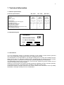
1.2 Identification plate
Sembdner
Maschinenbau GmbH
D - 82110 Germering
Model
No.
Wt.
Mot/kW
CE
1.3 Intended use
Your new landscaping machine is designed exclusively for the seeding of lawn surfaces (intended
use). Any use apart from seeding lawns cannot be considered as intended.
The manufacturer is not responsible for any damages resulting from use other than intended; the user
bears all such risk to a sole and exclusive extent. Complying with the intended use also includes
heeding the operation, maintenance and servicing conditions stipulated by the manufacturer.
This landscaping machine may only be used, serviced and/or repaired by persons familiar with the
machine and aware of its inherent dangers.
Adherence must be paid to the relevant accident prevention regulations as well as all other generallyrecognized technical and occupational safety regulations and traffic-related codes.
Unauthorized arbitrary changes performed on a machine absolve the manufacturer from any liability
attributable to damages resulting from such modifications.
4
2 Safety Information
2.1 Warning notices
Before using for the first time, read through the user manual and heed all safety instructions!
Caution sign
!
This symbol is found throughout this manual and alerts you to a potentially hazardous condition.
2.2 General safety data
Observe all generally-recognized safety regulations and accident prevention measures apart from
those indicated in this manual. Provide any other user of this machine with all safety instructions.
Minors under the age of 18 years old may not operate this landscaping machine.
Users are required to familiarize themselves with all mechanisms and control elements and their
functions before beginning operation. By the time the machine is in operation, it will be too late.
Before moving with the machine: check your immediate vicinity (children!); ensure your range of vision
is sufficient.
Do not leave the engine running in closed spaces: exhaust gases may be highly toxic!
The driver should wear tight-fitting clothing. Avoid loosely-fitting clothing.
Caution is required when handling fuel - increased fire risk.
Never refuel in the proximity of open flames or ignitable sparks.
Do not refuel the tank with the engine running.
Gasoline spilled on a hot engine increases the risk of fire or explosion; let engine cool down first.
Do not smoke while refueling.
2.3 User selection and qualification
Only responsible and capable personnel are to operate the landscaping machine. Heed legally
permissible minimum age. The owner is responsible for all necessary training of the skilled and/or
instructed personnel selected.
It is recommended that the owner be fully convinced of the level of knowledge the persons the owner
authorizes to operate the machine hold prior to any use of the machine with respect to the following
items:
knowledge of the contents of this manual
knowledge of all safety and operational procedures contained herein
knowledge of all applicable accident prevention regulations
Allow only trained or instructed persons to use this machine. Clearly specify personnel responsibilities
regarding operation, maintenance and repair.
5
2.4 Safety information when operating
Strict compliance is to be paid to all references provided regarding operational safety as well as all
items of general safety and accident prevention to be implemented or observed prior to, during and
following operation.
Non-compliance may result in accidents and thus physical injuries.
Maintain a safe distance when in reverse in enclosed spaces or near stationary objects.
Safety devices may not be disconnected or modified contrary to their intended purpose.
This landscaping machine is only to be operated when all protective and safety-related devices,
including detachable protective equipment and emergency stop mechanisms, are functional.
Retrofittings and modifications to this machine are prohibited.
The operator must ensure the proper, reliable and safe operation of this landscaping machine prior to
each use.
Donotl
eav
et
hemachi
ne’
soper
at
orst
at
i
onwhenwor
ki
ng.
2.5 Safety information when servicing
The setting, maintenance and repair procedures specified in this manual are only to be performed by
qualified personnel.
All adjustments, maintenance and repair procedures may only be performed when the engine has
been turned off and the spark plug terminal disconnected.
Ensure safe and environmentally-sound disposal of service fluids and consumable supplies as well as
replacement parts!
To avoid injury, use only reliable and suitable tools and materials during adjustments, servicing and
repair work.
Reattach all safety devices to the machine once all work has been completed.
Regularly check all retaining devices (screws, etc.) for tightness; tighten as necessary.
2.6 Safety instructions for operators
- wear tight-fitting clothing
- wear protective gloves
- wear ear protection
6
2.7 Machine dimensions and symbols
Machine dimensions:
Seed bin height:
RS 60 N / 65 cm
RS 80 N / 65 cm
RS 100 N / 65 cm
Total height:
RS 60 N / 95 cm
RS 80 N / 95 cm
RS 100 N / 95 cm
Total width:
RS 60 N / 80 cm
RS 80 N / 100 cm
RS 100 N / 120 cm
Total length:
RS 60 N / 175 cm
RS 80 N / 175 cm
RS 100 N / 175 cm
Symbols:
Travel direction:
reverse
Seed bin:
closed
Seed bin:
open
Travel direction:
forward
Wear ear protection
Do not open or remove
protective devices when
engine is running.
Never open or remove
protective devices when
engine is running.
7
3 General
3.1 Limitation of liability
All technical information, specifications and instructions contained in this manual for the operation and
maintenance of the landscaping machine correspond to the latest technology and are provided to the
best of our knowledge based on our past experience and scope of knowledge.
We reserve the right to make technical changes related to the ongoing development of the landscaping
machine described in this manual. Thus, no claims are to be inferred from the information, illustrations
and/or specifications provided in this manual.
We are not liable for any damage or malfunctioning resulting from operational error, non-compliance
with this manual or from improper repairs.
The Sembdner Maschinenbau GmbH company is herewith absolved of liability for any and all damage
resulting from the use of non-original replacement parts and/or accessories.
All translations provided are to the best of our knowledge. As such, we cannot be held liable for any
errors in translation, even should we have provided or ordered such translation ourselves.
The German text is to prevail as the definitive text.
3.2 Warranty
Warranty claims are to be filed immediately after a determination of damage has been made; include
all relevant purchasing data. All complaints must be confirmed by our office. Expendable parts are not
covered under the warranty.
The warranty becomes void upon:
- improper operation
- use other than that as intended
- unauthorized equipment
- use of non-original replacement parts
3.3 Testing standards
Thesoundpr
essur
el
ev
el
measur
edatt
heoper
at
or
’
searmustnotexceed85 dB(A).
Sound pressure measurement corresponds to the guidelines set forth by the Bundesverbandes der
landwirtschaftlichen Berufsgenossenschaft {German Federal Agricultural Association} for manuallyguided machines.
3.4 Accident prevention regulations
The accident prevention regulations of the Gartenbau-Berufsgenossenschaft {Horticulture Association}
are to apply.
8
4 Transport/Initial Startup
4.1 Packing
The landscaping machine is braced to its transport pallet with tension straps and packed in sheathing
cardboard and strapping.
4.2 Scope of delivery
Check for completeness of all parts and accessories upon taking delivery of your landscaping
machine. All claims regarding parts which may have become damaged or lost during transport are to
be filed with the shipping firm.
4.3 Loading
Hoisting elements in the form of two closed suspension grommets are provided on the machine frame
for loading the landscaping machine.
!
Keep off floating load!
When loading, only use hoisting equipment which corresponds to current safety standards.
When loading with planks, use only loading planks specifically suited thereto.
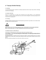
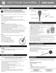
4.4 Measures prior to initial start-up
Instructions for assembling the control elements (removed for packing reasons):
Turn handlebar 1 180° to the rear and adjust to desired height. Firmly tighten the 2 fixing screws 2.
Insert cut-off lever 3 for the seed discharge into the knuckle joint. Turn the fixing screw into the cut-off
lever bore and tighten.
Affix adjustment ring 4 behind the lever mounting and tighten. Position gearshift lever 5 so it points
rearward to the control shaft, ensuring when doing so that the fixing screw is seated in the bore, then
tighten.
Mount the tensioning spring for the control lever release on the lever.
9
5 Operation
5.1 Engine
The engine is an air-cooled four-stroke engine which runs on normal unleaded gasoline.
!
Do not leave the engine running in a closed space:
exhaust gases may be highly toxic!!
Startup:
Before starting the engine, ensure the F/R travel direction lever is in neutral/idle position.
Set throttle on the handlebar to max.
Choke control: Shift the lever on the engine into the Choke or Start position.
Gently pull on the starter grip until you feel a slight resistance, then firmly pull all the way.
Don’
tl
ett
hest
ar
t
erhandl
esnapbackagai
nstt
heengi
ne. Carefully ease the handle back in order to
avoid damaging the starter.
While the engine is warming up, gradually push the choke lever into the open/run position. A warm
engine requires less choke control than a cold engine.
Oil warning system:
The oil warning system serves to help you avoid damaging the engine. Should there be an insufficient
volume of engine oil in the crankcase, the oil warning system will switch the engine off automatically. In
the event the engine stops and will not restart at all, it is advisable to check the oil level before any
further troubleshooting.
Do not perform any maintenance while the engine is running.
!
In order to avoid unintentional starts: disconnect spark plug terminal.
Air filter:
Never run the engine without the air filter since this leads to accelerated engine wear. Examine the air
filter elements to ensure they are clean and in good condition. Clean the primary filter as required,
replace paper filter cartridge when heavy accumulations of dirt have built up.
Oil change:
First oil change after 5 hours, then after each 50 hours of operation or on a seasonal basis.
Use SAE 30 motor oil for engine and transmission. Major maintenance and repairs should only be
performed by specialist repair shops.
The engine is from another manufacturer.
For exact information about its operation and maintenance,
refer to the engine manufacturer’
soper
at
i
ngi
nst
r
uct
i
ons as enclosed!
10
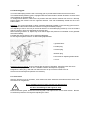
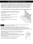
5.2 Reversing gear
Your new landscaping machine has a reversing gear to provide both forward and reverse motion.
The toothed wheel-planetary gear is equipped with two brake bands to enable forward or reverse travel
upon operation of gearshift lever 1.
To change travel direction, shift into the O-position and wait until the machine has come to a full stop
before shifting the machine into the opposite direction. This will considerably extend the life of the
brake bands!
Adjusting: The screws 5 marked in yellow, extending diagonally upward on the reversing gear serve for
adjusting the brake bands should the machine no longer accelerate properly.
The adjusting screw to the rear (in the travel direction of the landscaping machine) is for the forward
gear; the screw in front is for adjusting the reverse gear.
After loosening locknuts 6, adjust only so far that a slight end pressure is noticeable on the gearshift
lever when shifting.
Forward and reverse gear are to be adjusted individually.
Do not forget to tighten locknuts 6 after making adjustments!
1 gearshift lever
2 oil filler plug
3 oil level plug
4oil drain plug
5 set screw for adjusting brake bands
6 locknut
Reversing gear oil change: First oil change after 30 hours of operation, then after each 100 hours.
Loosen oil drain plug 4, drain oil into a suitable container and dispose of properly.
Retighten the drain plug, refill with new SAE 30 motor oil up to oil level control screw 3.
Check oil level monthly and replenish as necessary.
5.3 Chain drive
After the first few hours of operation, chain tension will have slackened somewhat and the drive chain
will need to be re-tightened.
Never retighten the drive chain without first disengaging
!
the drive and waiting for the engine to stop.
Remove the track guard, loosen the tensioning idler, and adjust to the correct chain tension. Be sure
to reaffix the protective covering after adjusting the chain!
11
5.4 Safety circuit
This landscaping machine is equipped with a safety circuit.
Ameasur
eofdoubl
edsaf
et
yi
sat
t
ai
nedbyasol
enoi
dswi
t
chont
her
ev
er
si
nggearandadeadman’
s
handle on the handlebar.
The engine cannot be started unless the travel direction shift lever is in the O-position.
Bef
or
eoper
at
i
ngt
he“
f
or
war
d–r
ev
er
se”gear
shi
f
tl
ev
er
,t
hedeadman’
shandl
emustbepul
l
edt
ot
he
handl
ebar
,ot
her
wi
set
hemachi
ne’
ssaf
et
yci
r
cui
twi
l
l
t
ur
nt
heengi
neof
f
.
The dead man’
s handl
e mustr
emai
n pulled during all travel, otherwise the engine will shut off
immediately.
Thedeadman’
shandl
eser
v
esasanemergency shut-off switch; in a dangerous situation calling for
an immediate stop, simply release.
!
Caution: The engine will still be running due to momentum lag!
Maintain a safe distance when in reverse in enclosed spaces or near stationary objects.
!
Donott
i
edownt
hesaf
et
yswi
t
chl
ever(
deadman’
shandl
e)
!
Checkt
hef
unct
i
oni
ngoft
hesaf
et
yswi
t
ch/
deadman’
shandl
epr
i
ort
oeachuse.
Modifications to the saf
et
yci
r
cui
t
/
deadman’
shandl
ear
est
r
i
ct
l
yf
or
bi
dden.
Michel in der Suppenschüssel
and
Pippi in Taka-Tuka-Land
I have been googling for the English titles without avail. Can it be that there are no English versions of
these books (or in this case musicals)?
Any help much appreciated.
Emil in the Soup Tureen - http://www.kirjasto.sci.fi/alindgr.htm & http://us.imdb.com/Title?0066227
Pippi in the South Seas (1974) (USA) http://us.imdb.com/Title?0066227
Checking the safety circuit
When t
he dead man’
s handl
ei
sr
el
eased,t
he saf
et
yci
r
cui
tmust prevent the engine from both
directions of travel prior to the gearshift lever being engaged.
Upon safety circuit malfunction, check the setting of the safety switch/trip cam on the reversing gear
unit as well as the cable and the cable connections.
Safety switch/trip cam settings
For the basic setting, secure the trip cam to the shaft of the reversing gear unit sucht
hatt
hecam’
sf
l
at
surfaces are parallel (vertically) to the safety switch in forward/reverse gear. The safety switch sprocket
should now be abutting the surfaces.
For further fine-tuning, the trip cam can be rotated on the shaft or the safety switch clearance to the trip
cam can be adjusted.
The trip cam should only press on the switch when the gearshift lever is in the O-position (see
schematic diagram).
12
5.5 Landscaping machine operation
Pre-rolling:
Pre-rolling breaks up larger clods of earth so that seeds will not be buried too deeply nor be covered by
excessive soil.
Sowing:
The sowing mechanism features a shaft of wear-resistant Perlon brushes which prove to be very
effective against small foreign objects and tend not to jam as is the case with more rigid equipment.
Precise seed allocation is provided on a large scale.
The seeds held within the seed bin are ejected from the brush shaft through an adjustable perforated
plate once the locking cap has been opened, thereby falling through the seed deflector (simultaneously
a windscreen plate).
Raking the seed into the soil:
Our patented power-driven seed dibbler with cleaning cage also works in pebbly, clumpy or damp soil
without fail.
Behind the seed discharge, the dibbler lodges the seeds into the soil. The dibbler is driven in such a
way that each individual spike will make a raking movement approximately 3 cm long (roll delay).
This works more seed into the ground than if the dibbler were simply to roll along atop the soil.
Finish-rolling:
Finish-rolling compresses the surface of the soil and the seed evenly, allowing the seed to germinate
faster. Advantages of finish-rolling include how it allows for easy steering and turning of the machine
without displacing soil and how it cannot become clogged by stones or clumps of earth. Detrimental
soil compaction is a thing of the past with the light weight of the SEMBDNER RS.
Operating the landscaping machine:
The angled control lever for the seed discharge is located within reach of the operator station.
Open = vertical / Closed = to the right.
To seed, open the control lever for the seed discharge and immediately bring the gearshift lever into
f
or
war
d dr
i
v
e;t
he dead man’
shandl
e on the handlebar must now be pulled to avoid the engine
switching off.
When turning or going in reverse, close the seed discharge.
If seeding is paused within an area to be sown, run the machine approximately 15 cm backward before
continuing work so that there will be no unseeded strips.
Care must be taken that sowing follows in a precise lane-to-lane orientation to avoid both doublesowing of lanes as well as omitting any spots.
In order to preclude any such errors when using very high-grade lawn seeding, sowing can also
transpire crosswise with half the amount of seed. This function largely compensates for any seeding
errors due to imprecise driving.
When turning the machine or running in reverse in tight spaces
!
or near stationary objects: Always ensure you maintain a safe distance!
Turning the machine is a function of just the large pressure roller when you press downward on the
handlebar; reduce driving speed at the same time with the throttle.
Adjusting the dibbler: the infeed depth of the dibbler can be adjusted and/or switched off completely
by means of the control handle on the left side of the machine, doing so allows the machine to be used
as just a roller.
When sowing, dibbler infeed depth should be no greater than 2 cm. If necessary, the control lever can
bel
i
f
t
edoutoft
hef
i
xedal
i
gni
ngbor
e,r
esul
t
i
ngi
na“
f
l
oat
i
ng”di
bbl
er(in free suspension).
Disengage the dibbler when not in actual use to prevent the dibbler spikes from becoming damaged.
13
Filling the seed:
Before filling the seed into the sowing machine, the lawn mixture must be fully remixed since it may
have become separated or unsettled during its transport!
Setting the seed quantity:
The seed quantity per m² is set with the adjustable lever on the large dial at the front of the seed bin.
Thedi
al
’
snumber
sdonotr
ef
ert
ogr
ams,butar
eonl
yr
ef
er
encepoi
nt
s.At“
0,
”seed discharge is
blocked completely.
Determining the seed quantity per m²:
There are two options; the seed catcher bin (mounted over the pre-roller with two hinged flaps) must
first be pushed onto the seed deflector in both.
(1) Model RS 60 N
Model RS 80 N
Model RS 100 N
measure a distance of 16.5 m and then set off.
measure a distance of 12.5 m and then set off.
measure a distance of 10.0 m and then set off.
In each case, this will result in a seed quantity for 10 m² in the seed catcher bin; the desired value is
determined and set by appropriately adjusting the seed dial.
(2) The seed bin has a V-belt pulley and a clutch which must be disengaged for the following. Pull out
the drive pin and give a quarter-turn to prevent reengagement. At the opposite side of the machine,
after opening the seed discharge, use the crank (found in the toolbox) on the agitator shaft to make
even rotations as follows:
Model RS 60 N
Model RS 80 N
Model RS 100 N
15½ rotations
11½ rotations
9
rotations
In each case, this will result in a seed quantity for 10 m² in the seed catcher bin; the desired value is
determined and set by appropriately adjusting the seed dial.
Do not forget to reengage the clutch.
NOTES
…………………………………………………………………………………………………………………….
.
.
…………………………………………………………………………………………………………………….
.
.
…………………………………………………………………………………………………………………….
.
.
…………………………………………………………………………………………………………………….
.
.
…………………………………………………………………………………………………………………….
.
.
…………………………………………………………………………………………………………………….
.
.
14
6 Servicing/Maintenance
6.1 Maintenance information
All maintenance, servicing and modifications are only to be performed
!
when the engine is off and the spark plug terminal disconnected!
Check engine oil level before each start-up. In addition, observe all maintenance and servicing
instructions in the enclosed manual from the engine manufacturer.
Reversing gear unit - Check oil level more frequently; adhere to the maintenance schedule and
settings as specified in Sec. 5.2.
Thef
unct
i
oni
ngoft
hesaf
et
yci
r
cui
t
/
deadman’
shandl
emustbecheckedbef
or
eeachst
ar
t
-up of the
landscaping machine (see the description given in Sec. 5.4).
Check the functioning of the sowing mechanism with the seed discharge lever.
When the seed discharge lever is sluggish, loosen the four fixing screws on the seed box frame and
remove the seed box from the machine frame. Extract the locking plate of the seed volume regulator
and clean the guide with a wire brush.
After any maintenance, servicing or modification work:
!
reaffix all chain and belt guard covers
and check the functioning of the safety switch!
All ball bearings are sealed with lifetime-lubricant and thus maintenance-free!
6.2 Troubleshooting
Machine malfunctions which require any greater degree of effort should always be performed by
specialist repair shops. Improper repairs can cause greater damage.
The engine does not turn over with the reverse starter:
Is there fuel in the tank?
Is there sufficient oil in the engine? (warning light for oil deficiency-cutoff blinks)
Has the stop control been switched to the ON position?
Check spark plug for ignition spark.
Check the safety circuit setting for a break in the gate trigger current (see the description in Sec. 5.4).
Should the engine still not start, please visit an authorized engine repair shop!
The reversing gear governs t
hemachi
ne’
sf
or
war
dandr
ev
er
semov
ement
. Should you experience
notably sluggish machine acceleration in one of these directions of travel, adjust for brake band wear
on the setting screws as described in Sec. 5.2.
6.3 Replacement parts
Use only original replacement parts from the SEMBDNER company, otherwise you will void your
warranty. When ordering replacement parts, please provide your machine number as well as the
technical data from the identification plate.
6.4 Customer service
Technical information can be requested from our own qualified personnel or our retailers, agricultural
dealers and engine specialists. Our foreign customers can call on our authorized national
representatives/workshops. If necessary, you can also contact our factory for fast and friendly
assistance.
6.5 Customer service addresses
A list of customer service centers for the respective engine manufacturer for purposes of maintenance
and repair work has been included along with this manual.
15
7 Accessories
Rollers:
Your landscaping machine comes with planed pressure rollers as standard equipment. As a special
optional accessory for all our landscaping machines, delivery can also include lattice rollers as prerollers and/or pressure rollers instead of the planed rollers.
Tarpaulin cover:
Tarps made from high-quality weather-proof plastic tarpaulin for protecting your landscaping machine.
Seed dibbler for golf course greens:
Models RS 60 N, RS 80 N and RS 100 N can be equipped with special seed dibblers for seeding golf
course greens. These golf dibblers have considerably more spikes and are ideally-suited for working
the lawn seed into the substrate areas of the greens. Exchanging dibbler rollers is a quick and virtually
effortless process.
Studding equipment:
Our studding device takes the form of a perforated roller in place of the front roller and is an
economical auxiliary unit for our RS 60 N and RS 80 N models when reseeding lawns in need of
restoration. The uniform punched pattern of approximately 1200 cuts/m² produces excellent results
when reseeding.
Fertilizer spreader:
A fertilizer spreader is available as an accessory for all three working widths of the landscaping
machine. Mounting is an uncomplicated and virtually effortless process.
The fertilizer spreader frame is fit into the machine frame profile tubing openings and affixed with two
screws. After mounting the V-belt drive pulley on the pressure roller, the V-belt is tensioned with a
tensioning idler. Afterwards, mount the belt guard cover! To provide balance, a counterweight frame is
inserted into the front profile tubing openings of the machine frame and fastened with two screws.
A counterweight corresponding to each respective machine model is part of each delivery.
Mounting the fertilizer spreader on the RS 60 N / RS 80 N / RS 100 N
1. Secur
emachi
nehandl
ebari
nt
hemount
i
ng’
ssecond
hole from the top.
2. Insert fertilizer spreader into the profile tubing openings
and tighten.
3. Screw belt tightener onto the fertilizer spreader mounting
and tension the belt.
4. Insert counterweight frame into the profile tubing
openings and tighten.
5. Slide the V-belt pulley over the hub of the
agitator drive pulley and tighten.
16
8 Declaration of Conformity
Declaration of Conformity
in compliance with the EC guidelines
Sembdner Maschinenbau GmbH
Sembdner Strasse 1
82110 Germering
herewith declares that the products:
Landscaping Machine Model RS 60 N
Landscaping Machine Model RS 80 N
Landscaping Machine Model RS 100 N
to which this declaration relates,
are in conformity with the relevant safety and health
provisions stipulated by EC Directive 98 / 37 / EC.
Germering, Dec. 7, 2001
Olaf Stauß
General Manager
17
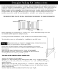
Schaltplan Sicherhheitsschaltung
Safety circuit wiring diagram
Schaltnocke
(Getriebeschalthebel in O-Stellung)
Trip cam
(gearshift lever in O-position)
Öffner
Break contact element
Totmannhebel am Führungsholm
Deadman’
shandl
eonhandl
ebar
Motor
Engine
Zündspannung
Ignition voltage
Sicherheitsschalter am Wendegetriebe
Safety switch on reversing gear
Chassis / Kurzschlußkontakt
Short-circuit contact