1
Model No.
TH-50LFC70U TH-50LFC70W
TH-65LFC70U TH-65LFC70W
TH-80LFC70U TH-80LFC70W
TH-50LFC70E
TH-65LFC70E
TH-80LFC70E
Operating Instructions
Display Operations
FULL HD LCD Display (for business use)
English
Please read these instructions before operating your set
and retain them for future reference.
Dear Panasonic Customer
Welcome to the Panasonic family of customers. We hope that you will have many years of
enjoyment from your new LCD Display.
To obtain maximum benefit from your set, please read these Instructions before making
any adjustments, and retain them for future reference.
Retain your purchase receipt also, and note down the model number and serial number of
your set in the space provided on the rear cover of these instructions.
Visit our Panasonic Web Site
http://panasonic.net
Table of Contents
Before use
• Illustrations and screens in this Operating Instructions are images for illustration purposes, and may
be different from the actual ones.
• Descriptive illustrations in this Operating Instructions are created mainly based on the 50 inch model.
Important Safety Instructions.................................. 1
FCC STATEMENT ...................................................... 2
Important Safety Notice ........................................... 3
Safety Precautions ................................................... 4
Accessories .............................................................. 7
Accessories Supply ................................................. 7
Contents in the CD-ROM ........................................ 7
Remote Control Batteries ........................................ 8
Connections .............................................................. 9
AC cord connection and xing, cable xing ............. 9
Speaker connection ................................................11
Video equipment connection ..................................11
VIDEO and COMPONENT / RGB IN connection.... 13
HDMI connection ................................................... 13
DVI-D IN connection .............................................. 14
PC Input Terminals connection .............................. 15
SERIAL Terminals connection ............................... 16
PC OUT connection............................................... 17
Example connection using the DIGITAL LINK
Terminal ................................................................. 18
Power On / Off......................................................... 19
Selecting the input signal ...................................... 21
Basic Controls ........................................................ 22
ASPECT Controls ................................................... 25
Digital Zoom ............................................................ 26
MULTI PIP ................................................................ 27
Memory Viewer Function ....................................... 28
Using Miracast(TM) ................................................ 33
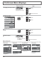
On-Screen Menu Displays ..................................... 34
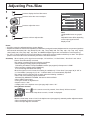
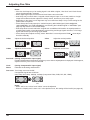
Adjusting Pos./Size ................................................ 35
Picture Adjustments ............................................... 38
Advanced settings ................................................. 39
Picture Proles ....................................................... 40
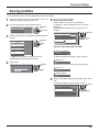
Saving proles ....................................................... 41
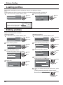
Loading proles ..................................................... 42
Editing proles ....................................................... 42
ii
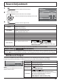
Sound Adjustment .................................................. 43
SDI Sound Output ................................................. 43
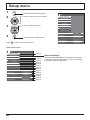
Setup menu ............................................................. 44
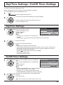
Day/Time Settings / On/Off Timer Settings .......... 45
Day/Time Settings ................................................. 45
On/Off Timer Settings ............................................ 45
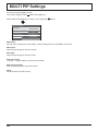
MULTI PIP Settings ................................................. 46
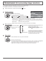
Screensaver (For preventing image retention) .... 47
Setup of Screensaver Time ................................... 48
ECO Mode settings................................................. 49
Customizing the Input labels................................. 50
Function Button Settings....................................... 51
Memory Viewer Settings ........................................ 52
Monitor Out ............................................................. 52
No activity power off .............................................. 53
Menu Display Duration / OSD Brightness ............ 53
OSD Language ........................................................ 53
Setup for Input Signals .......................................... 54
Component / RGB-in select ................................... 54
YUV / RGB-in select .............................................. 54
Signal menu .......................................................... 55
Options Adjustments ............................................. 58
Weekly Command Timer ....................................... 61
Audio input select .................................................. 63
Input Search .......................................................... 64
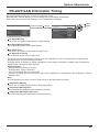
RS-232C/LAN Information Timing ......................... 65
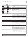
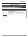
Troubleshooting ..................................................... 66
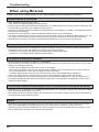
When using Miracast ............................................. 68
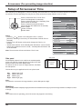
List of Aspect Modes ............................................. 69
Applicable Input Signals ........................................ 71
Shipping condition ................................................. 72
Command list of Weekly Command Timer ........... 73
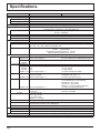
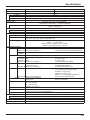
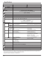
Specications ......................................................... 74
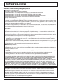
Software License .................................................... 77
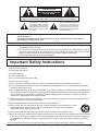
CAUTION
RISK OF ELECTRIC SHOCK
DO NOT OPEN
WARNING: To reduce the risk of electric shock, do not remove cover or back.
No user-serviceable parts inside. Refer servicing to qualied service personnel.
The lightning flash with
arrow-head within a triangle
is intended to tell the user
that parts inside the product
are a risk of electric shock
to persons.
The exclamation point within
a triangle is intended to
tell the user that important
operating and servicing
instructions are in the papers
with the appliance.
WARNING : To prevent damage which may result in re or shock hazard, do not expose this apparatus to
rain or moisture.
Do not place containers with water (ower vase, cups, cosmetics, etc.) above the set.
(including on shelves above, etc.)
WARNING : 1) To prevent electric shock, do not remove cover. No user serviceable parts inside. Refer servicing
to qualied service personnel.
2) Do not remove the grounding pin on the power plug. This apparatus is equipped with a three pin
grounding-type power plug. This plug will only t a grounding-type power outlet. This is a safety
feature. If you are unable to insert the plug into the outlet, contact an electrician.
Do not defeat the purpose of the grounding plug.
Important Safety Instructions
1) Read these instructions.
2) Keep these instructions.
3) Heed all warnings.
4) Follow all instructions.
5) Do not use this apparatus near water.
6) Clean only with dry cloth.
7) Do not block any ventilation openings. Install in accordance with the manufacturer’s instructions.
8) Do not install near any heat sources such as radiators, heat registers, stoves, or other apparatus (including
ampliers) that produce heat.
9) Do not defeat the safety purpose of the polarized or grounding-type plug. A polarized plug has two blades with
one wider than the other. A grounding type plug has two blades and a third grounding prong. The wide blade
or the third prong are provided for your safety. If the provided plug does not t into your outlet, consult an
electrician for replacement of the obsolete outlet.
10) Protect the power cord from being walked on or pinched particularly at plugs, convenience receptacles, and
the point where they exit from the apparatus.
11) Only use attachments / accessories specied by the manufacturer.
12) Use only with the cart, stand, tripod, bracket, or table specied by the manufacturer, or sold
with the apparatus. When a cart is used, use caution when moving the cart / apparatus
combination to avoid injury from tip-over.
13) Unplug this apparatus during lightning storms or when unused for long periods of time.
14) Refer all servicing to qualied service personnel. Servicing is required when the apparatus has been damaged
in any way, such as power-supply cord or plug is damaged, liquid has been spilled or objects have fallen into
the apparatus, the apparatus has been exposed to rain or moisture, does not operate normally, or has been
dropped.
15) To prevent electric shock, ensure the grounding pin on the AC cord power plug is securely connected.
1
FCC STATEMENT
This equipment has been tested and found to comply with the limits for a Class B digital device, pursuant to Part
15 of the FCC Rules. These limits are designed to provide reasonable protection against harmful interference
in a residential installation. This equipment generates, uses and can radiate radio frequency energy and, if not
installed and used in accordance with the instructions, may cause harmful interference to radio communications.
However, there is no guarantee that interference will not occur in a particular installation. If this equipment does
cause harmful interference to radio or television reception, which can be determined by turning the equipment
off and on, the user is encouraged to try to correct the interference by one or more of the following measures:
• Reorient or relocate the receiving antenna.
• Increase the separation between the equipment and receiver.
• Connect the equipment into an outlet on a circuit different from that to which the receiver is connected.
• Consult the dealer or an experienced technician for help.
This device complies with Part15 of the FCC Rules. Operation is subject to the following two conditions: (1) This
device may not cause harmful interference, and (2) this device must accept any interference received, including
interference that may cause undesired operation.
FCC CAUTION:
To assure continued compliance, follow the attached installation instructions and use only shielded
interface cables when connecting to computer or peripheral devices. Some recommended user provided
interface cables may require usage of the attached ferrite core kit(s), refer to interface cable connection
instructions for details. Any changes or modications not expressly approved by Panasonic Corp. of
North America could void the user’s authority to operate this device.
FCC Declaration of Conformity
Model No. TH-50LFC70U, TH-65LFC70U, TH-80LFC70U
Responsible Party:
Contact Source:
Panasonic Corporation of North America
Two Riverfront Plaza, Newark, New Jersey 07102-5490
Panasonic System Communications Company of North America
1-877-655-2357
CANADIAN NOTICE:
This Class B digital apparatus complies with Canadian ICES-003.
Note:
Image retention may occur. If you display a still picture for an extended period, the image might remain on the
screen. However, it will disappear after a while.
Trademark Credits
• VGA is a trademark of International Business Machines Corporation.
• Microsoft®, Windows®, Windows Vista®, and Internet Explorer® are the registered trademarks or trademarks of
Microsoft Corporation in the United States and/or other countries.
• Macintosh, Mac, Mac OS, OS X and Safari are the trademarks of Apple Inc. registered in the United States and
other countries.
• SVGA, XGA, SXGA and UXGA are registered trademarks of the Video Electronics Standard Association.
Even if no special notation has been made of company or product trademarks, these trademarks have been
fully respected.
• HDMI, the HDMI Logo, and High-Denition Multimedia Interface are trademarks or registered trademarks of
HDMI Licensing LLC in the United States and other countries.
• RoomView, Crestron RoomView and Fusion RV are registered trademarks of Crestron Electronics, Inc, and
Crestron Connected is the trademark of Crestron Electronics, Inc.
• Miracast is a trademark of Wi-Fi Alliance.
• Android is a registered trademark of Google Inc.
• iPad, iPhone, and iPod touch are trademarks of Apple Inc., registered in the U.S. and other countries.
2
Important Safety Notice
WARNING
1) To prevent damage which may result in re or shock hazard, do not expose this appliance to dripping
or splashing.
Do not place containers with water (ower vase, cups, cosmetics, etc.) above the set. (including on
shelves above, etc.)
No naked ame sources, such as lighted candles, should be placed on / above the set.
2) To prevent electric shock, do not remove cover. No user serviceable parts inside. Refer servicing to qualied
service personnel.
3) Do not remove the earthing pin on the power plug. This apparatus is equipped with a three pin earthing-type
power plug. This plug will only t an earthing-type power outlet. This is a safety feature. If you are unable to
insert the plug into the outlet, contact an electrician.
Do not defeat the purpose of the earthing plug.
4) To prevent electric shock, ensure the earthing pin on the AC cord power plug is securely connected.
CAUTION
This appliance is intended for use in environments which are relatively free of electromagnetic elds.
Using this appliance near sources of strong electromagnetic elds or where electrical noise may overlap with the
input signals could cause the picture and sound to wobble or cause interference such as noise to appear.
To avoid the possibility of harm to this appliance, keep it away from sources of strong electromagnetic elds.
IMPORTANT INFORMATION
If a display is not positioned in a sufciently stable location, it can be potentially hazardous due to falling. Many
injuries, particularly to children, can be avoided by taking simple precautions such as:
• Using cabinets or stands recommended by the manufacturer of the display.
• Only using furniture that can safely support the display.
• Ensuring the display is not overhanging the edge of the supporting furniture.
• Not placing the display on tall furniture (for example, cupboards or bookcases) without anchoring both the furniture
and the display to a suitable support.
• Not standing the displays on cloth or other materials placed between the display and supporting furniture.
• Educating children about the dangers of climbing on furniture to reach the display or its controls.
IMPORTANT: THE MOULDED PLUG
FOR YOUR SAFETY, PLEASE READ THE FOLLOWING TEXT CAREFULLY.
This display is supplied with a moulded three pin mains plug for your safety and convenience. A 10 amp fuse is
tted in this plug. Shall the fuse need to be replaced, please ensure that the replacement fuse has a rating of 10
amps and that it is approved by ASTA or BSI to BS1362.
Check for the ASTA mark
ASA
or the BSI mark
on the body of the fuse.
If the plug contains a removable fuse cover, you must ensure that it is retted when the fuse is replaced.
If you lose the fuse cover the plug must not be used until a replacement cover is obtained.
A replacement fuse cover can be purchased from your local Panasonic dealer.
Do not cut off the mains plug.
Do not use any other type of mains lead except the one supplied with this display.
The supplied mains lead and moulded plug are designed to be used with this display to avoid
interference and for your safety.
If the socket outlet in your home is not suitable, get it changed by a qualied electrician.
If the plug or mains lead becomes damaged, purchase a replacement from an authorized dealer.
WARNING : — THIS DISPLAY MUST BE EARTHED.
How to replace the fuse. Open the fuse compartment with a screwdriver and replace the fuse.
3
Safety Precautions
WARNING
Setup
This LCD Display is for use only with the following optional accessories. Use with any other type of optional
accessories may cause instability which could result in the possibility of injury.
(All of the following accessories are manufactured by Panasonic Corporation.)
• Pedestal .................................................................................... TY-ST42P50 (for 50 inch model)*,
TY-ST65P20 (for 65 inch model and 80 inch model)
• Mobile stand for Display ............................................................ TY-ST50PB2 (for 50 inch model),
TY-ST65PB2 (for 65 inch model),
TY-ST80LF70 (for 80 inch model)
• Mobile stand ..............................................................................TY-ST58PF20 (for 50 inch model)
• Wall-hanging bracket (vertical) .................................................. TY-WK42PV20 (for 50 inch model),
TY-WK70PV50 (for 80 inch model)
• Wall-hanging bracket (angled) .................................................. TY-WK42PR20 (for 50 inch model),
TY-WK65PR20 (for 65 inch model)
• Ceiling-hanging bracket ............................................................ TY-CE42PS20 (for 50 inch model)
• BNC Dual Video Terminal Board ............................................... TY-FB9BD
• HD-SDI Terminal Board ............................................................. TY-FB9HD
• HD-SDI Terminal Board with audio ........................................... TY-FB10HD
• Dual Link HD-SDI Terminal Board ............................................. TY-FB11DHD
• Dual HDMI Terminal Board ....................................................... TY-FB10HMD
• DVI-D Terminal Board ............................................................... TY-FB11DD
• Digital Interface Box .................................................................. ET-YFB100G
*Precaution for use of TY-ST42P50 (for 50 inch model)
Use a stand pole “for plasma display (long)” (part number: TBLA3679, TBLA3680).
We are not responsible for any product damage, etc. caused by use of the pedestal, wall-hanging bracket or
ceiling-hanging bracket made by other companies, or by failures in the installation environment for the pedestal,
wall-hanging bracket or ceiling-hanging bracket even during the warranty period.
Always be sure to ask a qualied technician to carry out set-up.
Small parts can present choking hazard if accidentally swallowed. Keep small parts away from young children. Discard
unneeded small parts and other objects, including packaging materials and plastic bags/sheets to prevent them from
being played with by young children, creating the potential risk of suffocation.
Do not place the Display on sloped or unstable surfaces, and ensure that the Display does not hang over the
edge of the base.
• The Display may fall off or tip over.
Do not place any objects on top of the Display.
• If water is spills onto the Display or foreign objects get inside it, a short-circuit may occur which could result in re
or electric shock. If any foreign objects get inside the Display, please consult your local Panasonic dealer.
Transport only in upright position!
• Transporting the unit with its display panel facing upright or downward may cause damage to the internal circuitry.
Ventilation should not be impeded by covering the ventilation openings with items such as newspapers, table
cloths and curtains.
For sufcient ventilation;
If using the pedestal (optional accessory), leave a space of 3 15/16” (10 cm) or more at the top, left and right,
and 2 3/4” (7 cm) or more at the rear, and also keep the space between the bottom of the display and the oor
surface.
If using some other setting-up method, follow the manual of it. (If there is no specic indication of installation
dimension in the installation manual, leave a space of 3 15/16” (10 cm) or more at the top, bottom, left and right,
and 2 3/4” (7 cm) or more at the rear.)
Cautions for Wall or ceiling Installation
• Wall or ceiling installation should be performed by an installation professional. Installing the Display incorrectly may
lead to an accident that results in death or serious injury. Use the specied accessories.
• If you terminate the use of the Display on the wall or ceiling, ask a professional to remove the Display as soon as possible.
• When mounting the Display on the wall, prevent the mounting screws and power cable from contacting metal
objects inside the wall. An electric shock may occur if they contact metal objects inside the wall.
Do not install the product to a place where the product is exposed to direct sunlight.
• If the screen is exposed to direct sunlight, the liquid crystal panel may have adverse effect.
4
Safety Precautions
When using the LCD Display
The Display is designed to operate on 110 - 127 or 220 - 240 V AC, 50/60 Hz.
Do not cover the ventilation holes.
• Doing so may cause the Display to overheat, which can cause re or damage to the Display.
Do not stick any foreign objects into the Display.
• Do not insert any metal or ammable objects into the ventilations holes or drop them onto the Display, as doing so
can cause re or electric shock.
Do not remove the cover or modify it in any way.
• High voltages which can cause severe electric shocks are present inside the Display. For any inspection, adjustment
and repair work, please contact your local Panasonic dealer.
Ensure that the mains plug is easily accessible.
An apparatus with CLASS I construction shall be connected to a mains socket outlet with a protective earthing
connection.
Do not use any power supply cord other than that provided with this unit.
• Doing so may cause re or electric shocks.
Securely insert the power supply plug as far as it will go.
• If the plug is not fully inserted, heat may be generated which could cause re. If the plug is damaged or the wall
socket is loose, they shall not be used.
Do not handle the power supply plug with wet hands.
• Doing so may cause electric shocks.
Do not do anything that may damage the power cable. When disconnecting the power cable, pull on the plug
body, not the cable.
• Do not damage the cable, make any modications to it, place heavy objects on top of it, heat it, place it near any
hot objects, twist it, bend it excessively or pull it. To do so may cause re and electric shock. If the power cable is
damaged, have it repaired at your local Panasonic dealer.
Do not remove covers and NEVER modify the Display yourself
• Do not remove the rear cover as live parts are accessible when it is removed. There are no user serviceable parts
inside. (High-voltage components may cause serious electrical shock.)
• Have the Display checked, adjusted, or repaired at your local Panasonic dealer.
If the Display is not going to be used for any prolonged length of time, unplug the power supply plug from
the wall outlet.
To prevent the spread of re, keep candles or other open ames away from this product at all times.
If problems occur during use
If a problem occurs (such as no picture or no sound), or if smoke or an abnormal odour starts to come out
from the Display, immediately unplug the power supply plug from the wall outlet.
• If you continue to use the Display in this condition, re or electric shock could result. After checking that the smoke
has stopped, contact your local Panasonic dealer so that the necessary repairs can be made. Repairing the Display
yourself is extremely dangerous, and shall never be done.
If water or foreign objects get inside the Display, if the Display is dropped, or if the cabinet becomes damages,
disconnect the power supply plug immediately.
• A short circuit may occur, which could cause re. Contact your local Panasonic dealer for any repairs that need to
be made.
5
Safety Precautions
CAUTION
When using the LCD Display
Do not bring your hands, face or objects close to the ventilation holes of the Display.
• Heated air comes out from the ventilation holes at the top of Display will be hot. Do not bring your hands or face,
or objects which cannot withstand heat, close to this port, otherwise burns or deformation could result.
Be sure to disconnect all cables before moving the Display.
• If the Display is moved while some of the cables are still connected, the cables may become damaged, and re or
electric shock could result.
Disconnect the power supply plug from the wall socket as a safety precaution before carrying out any
cleaning.
• Electric shocks can result if this is not done.
Clean the power cable regularly to prevent it becoming dusty.
• If dust built up on the power cord plug, the resultant humidity can damage the insulation, which could result in re.
Pull the power cord plug out from the wall outlet and wipe the mains lead with a dry cloth.
Do not burn or breakup batteries.
• Batteries must not be exposed to excessive heat such as sunshine, re or the like.
Cleaning and maintenance
The front of the display panel has been specially treated. Wipe the panel surface gently using only a cleaning
cloth or a soft, lint-free cloth.
• If the surface is particularly dirty, wipe with a soft, lint-free cloth which has been soaked in pure water or water in
which neutral detergent has been diluted 100 times, and then wipe it evenly with a dry cloth of the same type until
the surface is dry.
• Do not scratch or hit the surface of the panel with ngernails or other hard objects, otherwise the surface may
become damaged. Furthermore, avoid contact with volatile substances such as insect sprays, solvents and thinner,
otherwise the quality of the surface may be adversely affected.
If the cabinet becomes dirty, wipe it with a soft, dry cloth.
• If the cabinet is particularly dirty, soak the cloth in water to which a small amount of neutral detergent has been
added and then wring the cloth dry. Use this cloth to wipe the cabinet, and then wipe it dry with a dry cloth.
• Do not allow any detergent to come into direct contact with the surface of the Display. If water droplets get inside
the unit, operating problems may result.
• Avoid contact with volatile substances such as insect sprays, solvents and thinner, otherwise the quality of the
cabinet surface may be adversely affected or the coating may peel off. Furthermore, do not leave it for long periods
in contact with articles made from rubber or PVC.
Usage of a chemical cloth
• Do not use a chemical cloth for the panel surface.
• Follow the instructions for the chemical cloth to use it for the cabinet.
6
Accessories
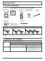
Accessories Supply
Check that you have the accessories and items shown
Operating
Instruction book
Software CD-ROM × 1 Remote Control
Transmitter
N2QAYB000691
Ferrite core × 2
J0KG00000014
Batteries for the Remote
Control Transmitter
(R6 (UM3) Size × 2)
Clamper × 1
TMME289
Cable tie × 2
TMM17499
Use the Ferrite cores
to comply with the EMC
standard. (see page 14)
Power supply cord
TH-50LFC70U, TH-65LFC70U, TH-50LFC70E, TH-65LFC70E,
TH-80LFC70U
TH-80LFC70E
TH-50LFC70W, TH-65LFC70W, TH-80LFC70W
Attention
Store small parts in an appropriate manner, and keep them away from young children.
Contents in the CD-ROM
The contents below are included in the supplied CD-ROM.
Instruction
(PDF)
Software
Operating Instructions - Display Operations
Operating Instructions - Network Operations
Operating Instructions - Wireless Manager ME
Software license
GNU GENERAL PUBLIC LICENSE
GNU LESSER GENERAL PUBLIC LICENSE
Wireless Manager ME (Windows/Mac)
Allows the image on the computer screen to be
sent wirelessly or via wired LAN.
Switch the input to Panasonic APPLICATION
before use. For more details, see the instruction
manual of Wireless Manager ME.
7
Accessories
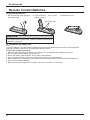
Remote Control Batteries
Requires two R6 batteries.
1. Pull and hold the hook, then open
the battery cover.
2. Insert batteries - note correct
polarity (+ and -).
3. Replace the cover.
“R6 (UM3)” size
+
+
-
Helpful Hint:
For frequent remote control users, replace old batteries with Alkaline
batteries for longer life.
Precaution on battery use
Incorrect installation can cause battery leakage and corrosion that will damage the remote control transmitter.
Disposal of batteries should be in an environment-friendly manner.
Observe the following precaution:
1. Batteries shall always be replaced as a pair. Always use new batteries when replacing the old set.
2. Do not combine a used battery with a new one.
3. Do not mix battery types (example: “Zinc Carbon” with “Alkaline”).
4. Do not attempt to charge, short-circuit, disassemble, heat or burn used batteries.
5. Battery replacement is necessary when remote control acts sporadically or stops operating the Display set.
6. Do not burn or breakup batteries.
7. Batteries must not be exposed to excessive heat such as sunshine, re or the like.
8
Connections
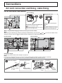
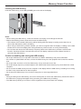
AC cord connection and xing, cable xing
For 50 inch and 65 inch models
AC cord xing
Unplug the AC cord
Plug the AC cord into the display unit.
Plug the AC cord until it clicks.
Note:
Make sure that the AC cord is locked on
both the left and right sides.
Unplug the AC cord pressing the
two knobs.
Note:
When disconnecting the AC cord, be
absolutely sure to disconnect the AC
cord plug at the socket outlet rst.
When using the Wall-hanging bracket (vertical) (for 50 inch model)
Note:
When using the Wall-hanging bracket (vertical)(TY-WK42PV20), use the holes
and
clamper is used on the hole
, the cables may be caught by the wall-hanging bracket.
50 inch model
to secure the cables. If the
65 inch model
Using the clamper
Secure any excess cables with clamper as required.
Note:
One clamper is supplied with this unit. In case of securing cables at three positions, please purchase it separately.
If you need more clampers, purchase them from your dealer. (Available from the customer service)
1 Attach the clamper
To remove from the unit:
2 Bundle the cables
To loosen:
hole
snaps
Insert the clamper
in a hole.
Keep pushing
both side snaps
hooks
Set the
tip in the
hooks
knob
Keep
pushing
the knob
9
Connections
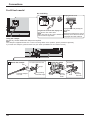
For 80 inch model
AC cord xing
Unplug the AC cord
Plug the AC cord into the display unit.
Plug the AC cord until it clicks.
Note:
Make sure that the AC cord is locked on
both the left and right sides.
Unplug the AC cord pressing the
two knobs.
Note:
When disconnecting the AC cord, be
absolutely sure to disconnect the AC
cord plug at the socket outlet rst.
Using the clamper
Secure any excess cables with clamper as required.
Note:
One clamper is supplied with this unit. In case of securing cables at four positions, please purchase it separately.
If you need more clampers, purchase them from your dealer. (Available from the customer service)
1 Attach the clamper
To remove from the unit:
2 Bundle the cables
To loosen:
hole
snaps
Insert the clamper
in a hole.
10
Keep pushing
both side snaps
hooks
Set the
tip in the
hooks
knob
Keep
pushing
the knob
Connections
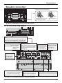
Speaker connection
Please use 8 /10 W speaker.
Black
Red
1 While pressing the lever,
Red
Black
2 Return the lever.
insert the core wire.
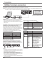
Video equipment connection
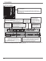
For 50 inch and 65 inch models
SLOT: Terminal board (optional accessories) insert slot (see page 4)
Note:
The right side slot is for terminal board with 2-slot
width. The terminal board with 1-slot width does
not function when installed in the right side slot.
AV IN (VIDEO): Composite Video Input
Terminal (see page 13)
COMPONENT/RGB IN: Component/RGB
Video Input Terminal
(see page 13)
PC OUT:
Monitor Out Terminal.
Video signals being reproduced on
the display are output to another
sub monitor as PC video signals.
(see page 17)
SERIAL:
Serial Control Terminal.
Control the Display
by connecting to
PC. (see page 16)
AUDIO 2 IN:
Audio input terminal
shared with DVI-D
IN and PC IN.
(see page 14, 15)
AUDIO 1 IN:
Audio input terminal
shared with VIDEO
and COMPONENT/
RGB IN. (see page 13)
PC IN: PC Input Terminal
Connect to video terminal of PC or equipment with
Y, PB(CB) and PR(CR) output (see page 15).
DVI-D IN: DVI-D Input Terminal (see page 14)
AV IN (HDMI 1, HDMI 2): HDMI LAN, DIGITAL LINK*
Connect to a DIGITAL LINK input terminal network to control the
Input Terminal (see page 13)
Display. Alternatively, connect to a device that sends video and
Connect to video equipment
audio signals via the DIGITAL LINK terminal. (see page 18)
such as VCR or DVD player.
* DIGITAL LINK is technology that enables signals such as audio and video to be transmitted using twisted pair cables.
For details, see the Operating Instructions - “Network Operations”.
11
Connections
For 80 inch model
SLOT: Terminal board (optional accessories) insert slot
(see page 4)
Note:
The upper side slot is for terminal board with 2-slot width. The
terminal board with 1-slot width does not function when installed in
the upper side slot.
AV IN (VIDEO): Composite Video Input Terminal
(see page 13)
COMPONENT/RGB IN: Component/RGB Video Input
Terminal (see page 13)
AUDIO 1 IN:
Audio input terminal
shared with VIDEO
and COMPONENT/
RGB IN. (see page 13)
SERIAL:
Serial Control Terminal.
Control the Display
by connecting to
PC. (see page 16)
AV IN (HDMI 1, HDMI 2): HDMI Input
Terminal (see page 13)
Connect to video equipment such as
VCR or DVD player.
PC IN: PC Input Terminal
Connect to video terminal of PC or
equipment with Y, PB(CB) and PR(CR)
output (see page 15).
DVI-D IN: DVI-D Input Terminal (see page 14)
PC OUT:
Monitor Out Terminal.
Video signals being
reproduced on the display
are output to another sub
monitor as PC video signals.
(see page 17)
AUDIO 2 IN:
Audio input terminal
shared with DVI-D IN and
PC IN. (see page 14, 15)
LAN, DIGITAL LINK*
Connect to a DIGITAL LINK input terminal network
to control the Display. Alternatively, connect to a
device that sends video and audio signals via the
DIGITAL LINK terminal. (see page 18)
* DIGITAL LINK is technology that enables signals such as audio and video to be transmitted using twisted pair cables.
For details, see the Operating Instructions - “Network Operations”.
12
Connections
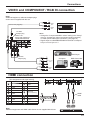
VIDEO and COMPONENT / RGB IN connection
Note:
Additional equipment, cables and adapter plugs
shown are not supplied with this set.
L
R
Stereo mini plug (M3)
AUDIO
OUT
VIDEO
OUT
Pin-BNC
Adapter plug
VCR
Notes:
AUDIO 1 IN:
Shared with VIDEO and
COMPONENT/RGB IN
• Change the “Component/RGB-in select” setting in the “Setup”
menu to “Component” (when Component signal connection)
or “RGB” (when RGB signal connection). (see page 54)
• Signals input to COMPONENT/RGB IN terminals correspond
to Sync on G or Sync on Y.
DVD Player
Pin-BNC
Adapter plug
Y
PB
Computer
RGB Camcorder
Y, PB, PR,
OUT
PR
L
R
AUDIO
OUT
HDMI connection
[Pin assignments and signal names]
Pin No.
1
2
3
4
5
6
7
8
9
10
Signal name
T.M.D.S Data2+
T.M.D.S Data2
Shield
T.M.D.S Data2T.M.D.S Data1+
T.M.D.S Data1
Shield
T.M.D.S Data1T.M.D.S Data0+
T.M.D.S Data0
Shield
T.M.D.S Data0T.M.D.S Clock+
Pin No.
11
Signal name
T.M.D.S Clock
Shield
12
T.M.D.S Clock-
13
CEC
14
Reserved
(N.C. on device)
15
16
17
18
19
SCL
SDA
DDC/CEC
Ground
+5V Power
Hot Plug Detect
19
18
HDMI
cable
3 1
4 2
Note:
Additional equipment and HDMI cable shown are not supplied with this set.
HDMI
AV OUT
HDMI
AV OUT
DVD player
13
Connections
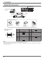
DVI-D IN connection
Shared with PC IN.
PC with DVI-D
video out
Stereo mini plug (M3)
Less than
Ferrite core Less than
1.97 inch (5 cm) (supplied) 1.97 inch (5 cm)
DVI-video cable (Within 5 m)
Installing the Ferrite core
1.
2.
Pull back the tabs
(in two places)
Open the
Ferrite core
DVI-D Input Connector
Pin Layouts
1
Pin No.
8
9
16
17
24
Connection port view
3.
1
2
3
4
5
6
7
8
9
10
11
12
4.
Fix the Ferrite
core with the
cable tie
Route the
cable through
and close
Signal Name
T.M.D.S. data 2T.M.D.S. data 2+
T.M.D.S. data 2 shield
DDC clock
DDC data
T.M.D.S. data 1T.M.D.S. data 1+
T.M.D.S. data 1 shield
Pin No.
13
14
15
16
17
18
19
20
21
22
23
24
Signal Name
+5 V DC
Ground
Hot plug detect
T.M.D.S. data 0T.M.D.S. data 0+
T.M.D.S. data 0 shield
T.M.D.S. clock shield
T.M.D.S. clock+
T.M.D.S. clock-
Notes:
• Additional equipment and cables shown are not supplied with this set.
• Use the DVI-D cable complying with the DVI standard. Image deterioration may occur depending on the length or
the quality of the cable.
14
Connections
PC Input Terminals connection
Shared with DVI-D IN.
COMPUTER
Conversion adapter
(if necessary)
(Female)
Mini D-sub 15p
RGB
PC cable
Audio
(Male)
Stereo mini plug (M3)
Connect a cable which matches
the audio output terminal on the computer.
Notes:
• With regard to the typical PC input signals that are described in the applicable input signals list (see page 71), adjustment
values such as for the standard picture positions and sizes have already been stored in this unit. You can add up to eight
PC input signal types that are not included in the list.
• Computer signals which can be input are those with a horizontal scanning frequency of 15 to 110 kHz and vertical scanning
frequency of 48 to 120 Hz. (However, the image will not be displayed properly if the signals exceed 1,200 lines.)
• The display resolution is a maximum of 1,440 × 1,080 dots when the aspect mode is set to “4:3”, and 1,920 × 1,080
dots when the aspect mode is set to “16:9”. If the display resolution exceeds these maximums, it may not be possible
to show ne detail with sufcient clarity.
• The PC input terminals are DDC2B-compatible. If the computer being connected is not DDC2B-compatible, you will
need to make setting changes to the computer at the time of connection.
• Some PC models cannot be connected to the set.
• There is no need to use an adapter for computers with DOS/V compatible Mini D-sub 15P terminal.
• The computer shown in the illustration is for example purposes only.
• Additional equipment and cables shown are not supplied with this set.
• Do not set the horizontal and vertical scanning frequencies for PC signals which are above or below the specied
frequency range.
• Component Input is possible with the pin 1, 2, 3 of the Mini D-sub 15P Connector.
• Change the “Component/RGB-in select” setting in the “Setup” menu to “Component”
(when Component signal connection) or “RGB” (when RGB signal connection). (see page 54)
Signal Names for Mini D-sub 15P Connector
5
4
10 9
3
2
8
1
7
6
15 14 13 12 11
Pin No.
Signal Name
Pin No.
Signal Name
Pin No.
Signal Name
1
R (PR/CR)
6
GND (Ground)
11
NC (not connected)
2
G (Y)
7
GND (Ground)
12
SDA
3
B (PB/CB)
8
GND (Ground)
13
HD/SYNC
4
NC (not connected)
9
+5 V DC
14
VD
5
GND (Ground)
10
GND (Ground)
15
SCL
Pin Layout for PC Input
Terminal
15
Connections
SERIAL Terminals connection
The SERIAL terminal is used when the Display is controlled by a computer.
Note: To use serial control for this unit, make sure to set the “Control I/F Select” in the “Network Settings” menu to
“RS-232C”. (refer to “Operating Instructions, Network Operations”)
(Male)
COMPUTER
9
5
8
4
7
3
6
2
1
Pin layout for SERIAL Terminal
RS-232C Straight cable
(Female)
D-sub 9p
Notes:
• Use the RS-232C straight cable to connect the computer to the Display.
• The computer shown is for example purposes only.
• Additional equipment and cables shown are not supplied
with this set.
The SERIAL terminal conforms to the RS-232C interface
specication, so that the Display can be controlled by a
computer which is connected to this terminal.
The computer will require software which allows the
sending and receiving of control data which satises the
conditions given below. Use a computer application such
as programming language software. Refer to the
documentation for the computer application for details.
Communication parameters
Signal level
Synchronization method
Baud rate
Parity
Character length
Stop bit
Flow control
RS-232C compliant
Asynchronous
9600 bps
None
8 bits
1 bit
None
Basic format for control data
The transmission of control data from the computer
starts with a STX signal, followed by the command, the
parameters, and lastly an ETX signal in that order. If
there are no parameters, then the parameter signal does
not need to be sent.
STX
C1 C2 C3
Start
(02h)
:
P1 P2 P3 P4 P5
ETX
Colon
Parameter(s)
(1 - 5 bytes)
3-character
command (3 bytes)
End
(03h)
Notes:
• If multiple commands are transmitted, be sure to wait for
the response for the rst command to come from this unit
before sending the next command.
• If an incorrect command is sent by mistake, this unit will
send an “ER401” command back to the computer.
• S1A and S1B of Command IMS are available only when
a dual input terminal board is attached.
• Consult your local Panasonic dealer for detail instructions
on command usage.
16
Signal names for D-sub 9P connector
Pin No.
2
3
5
4 • 6
7
8
1 • 9
Details
RXD
TXD
GND
Non use
(Shorted in this set)
NC
These signal names are those of computer specications.
Command
Command
PON
POF
AVL
AMT
IMS
Parameter
None
None
**
0
1
None
SL1
S1A
S1B
VD1
YP1
HM1
HM2
DV1
PC1
DL1
MG1
MV1
Control details
Power ON
Power OFF
Volume 00 - 63
Audio MUTE OFF
Audio MUTE ON
Input select (toggle)
SLOT input (SLOT INPUT)
SLOT input (SLOT INPUT A)
SLOT input (SLOT INPUT B)
VIDEO input (VIDEO)
COMPONENT/RGB IN input
(COMPONENT)
HDMI 1 input (HDMI1)
HDMI 2 input (HDMI2)
DVI-D IN input (DVI)
PC IN input (PC)
DIGITAL LINK input (DIGITAL LINK)
Miracast input (Miracast(TM))
Memory veiwer input
(MEMORY VIEWER)
With the power off, this display responds to PON
command only.
Connections
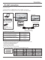
PC OUT connection
The image being reproduced on the display including the image input from video equipment can be displayed on
another sub monitor.
To use the function, set “Monitor Out” to “On” in “Setup”. (see page 52)
Note: Setting it to “On” will adjust the “Picture” menu values to the standard values.
Sub monitor
Computer, DVD player and
other video equipment
PC input terminal
(Female)
USB memory
(To be viewed in Memory
Viewer)
(Male)
Mini D-sub 15p cable
(Commercially available)
Input signals that can be output
Input signal
Output signal
HDMI input signal (HDMI 1, HDMI 2)
HDCP (copy protection) not supported
DVI input signal (DVI-D IN)
HDCP (copy protection) not supported
PC input signal (PC IN)
When “Component/RGB-in select” is set to
“RGB”
Memory Viewer screen (MEMORY VIEWER)
1,920 x 1,080@50 Hz or
1,920 x 1,080@60 Hz
1,920 x 1,080@50 Hz or
1,920 x 1,080@60 Hz
1,920 x 1,080@50 Hz or
1,920 x 1,080@60 Hz
1,920 x 1,080@60 Hz
Notes:
• The aspect ratio of the output signal is changed so that it can be shown on the screen.
• The following input signals cannot be output.
Component input (COMPONENT/RGB IN)
Composite video input (VIDEO)
Miracast image (Miracast(TM))
Wireless Manager (Panasonic APPLICATION)
Pin Layout and Signal Names of Monitor Out Terminal (Mini-D-sub 15P)
5
4
10 9
3
2
8
1
7
15 14 13 12 11
Pin No.
Signal Name
Pin No.
Signal Name
Pin No.
Signal Name
1
R
6
GND (Ground)
11
NC (not connected)
2
G
7
GND (Ground)
12
NC (not connected)
3
B
8
GND (Ground)
13
HD
4
NC (not connected)
9
+5 V DC
14
VD
5
GND (Ground)
10
GND (Ground)
15
NC (not connected)
6
17
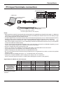
Connections
Example connection using the DIGITAL LINK Terminal
A twisted pair cable transmitter such as the Panasonic Digital Interface Box (ET-YFB100G) uses twisted pair cables
to transmit inputted video and audio signals, and these digital signals can be input to the Display via the DIGITAL
LINK terminal.
Display Connection Terminals
Control
Computer
When a Panasonic ET-YFB100G is used
Video Cassette Recorder
DVD Player
Computer
Note:
When connecting with DIGITAL LINK, be sure to congure each of the “Network Settings” settings.
For the cautions for DIGITAL LINK setting and connection, refer to “Operating Instructions - Network Operations”.
18
Power On / Off
Connecting the AC cord plug to the Display.
Connecting the plug to the Wall Outlet
Notes:
• Main plug types vary between countries. The power
plug shown at right may, therefore, not be the type
tted to your set.
• When disconnecting the AC cord, be absolutely sure
to disconnect the AC cord plug at the socket outlet
rst.
Power switch
Press the Power switch on the Display to turn the set
on: Power-On.
Power Indicator: Green
Power Indicator
Remote Control Sensor
[Starting up the network]
It takes some time for the network to start up just
after the power is turned on.
During that time, “Network Setup” in the “Setup”
menu is grayed out and cannot be set.
Press the
button on the remote control to turn the Display off.
Power Indicator: Red (standby)
Press the
button on the remote control to turn the Display on.
Power Indicator: Green
Turn the power to the Display off by pressing the
the Display is on or in standby mode.
switch on the unit, when
Note:
During operation of the power management function, the power indicator turns
orange in the power off state.
19
Power On / Off
When rst switching on the unit
Following screen will be displayed when the unit is turned on for the rst time.
Select the items with the remote control. Unit buttons are invalid.
OSD Language
Day/Time Settings
OSD Language
Select the
language.
2 Set.
1
English (UK)
Deutsch
Français
Italiano
Time MON 99:99
Set
Day
MON
Time
18:00
Español
ENGLISH (US)
Select “Day”
or “Time”.
2 Setup “Day”
or “Time”.
1
Day/Time Settings
Day/Time Settings
1
Select “Set”.
2
Set.
Time TUE 99:99
Set
Day
TUE
Time
18:00
Notes:
• Once the items are set, the screens won't be displayed when switching on the unit next time.
• After the setting, the items can be changed in the following menus.
OSD Language (see page 53)
Day/Time Settings (see page 45)
Power ON message
The following message may be displayed when turning the unit power ON:
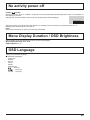
No activity power off Precautions
’No activity power off’ is enabled.
If “No activity power off” in Setup menu is set to “Enable”, a warning message is displayed every time the
power is turned ON. (see page 53)
Power Management Information
Last turn off due to 'Power management'.
If “Power management” is functioned, an information message is displayed every time the power is turned ON.
(see page 49)
These message displays can be set with the following menu: Options menu
Power On Message (No activity power off)
(see page 61)
Power On Message (Power Management)
(see page 61)
Displaying network information
The network information for the Display will be displayed in the following scenarios.
The power is turned ON with Panasonic APPLICATION selected as the input.
The input is switched to Panasonic APPLICATION.
The
button is pushed with Panasonic APPLICATION selected as the input.
Display example:
Panasonic APPLICATION
S-DIRECT Name1234 Proj1234
Display ID
Display name
Wireless LAN network number
20
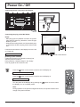
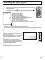
Selecting the input signal
Press to select the input signal to be played back from the equipment which has been
connected to the Display.
Alternatively you can press
, press
to select the input and press
.
INPUT
HDMI1
HDMI2
SLOT INPUT
VIDEO
COMPONENT
PC
DVI
DIGITAL LINK
Miracast(TM)
Panasonic APPLICATION
MEMORY VIEWER
HDMI input in HDMI 1 terminal
HDMI input in HDMI 2 terminal
Input signal in a Terminal Board*1
Composite video input in VIDEO terminal
Component/RGB input in COMPONENT/RGB IN terminal*2
Computer's signal input in PC IN terminal
DVI-D input in DVI-D IN terminal
DIGITAL LINK input in DIGITAL LINK terminal
Select this input when using the Miracast function. (see page 33)
Select this input when using “Wireless Manager” via wired/wireless LAN.
Select this input when using the Memory Viewer function. (see page 30)
*1 “SLOT INPUT” appears when an optional Terminal Board is connected.
When a Terminal Board with dual input terminals is connected, “SLOT INPUT A” and “SLOT INPUT B” will appear.
When a Terminal Board incompatible with the Display is installed, “Non-Compatible Function Board” is displayed.
*2 “COMPONENT” may be displayed as “RGB” depending on the setting of “Component/RGB-in select”.
(see page 54)
Notes:
• Selecting is also possible by pressing the INPUT button
on the unit.
• Outputs the sound as set in “Audio input select” in the
Options menu. (see page 63)
• Select to match the signals from the source connected
to the component/RGB input terminals. (see page 54)
• Image retention (image lag) may occur on the LCD
display panel when a still picture is kept on the panel for
an extended period. To prevent such a problem, using
the screensaver is recommended. (see page 47)
• The connection of the Wireless Manager is interrupted if
the input is switched from Panasonic APPLICATION to
Miracast(TM) or MEMORY VIEWER.
The connection of Miracast is interrupted if the input is
switched from Miracast(TM) to Panasonic APPLICATION
or MEMORY VIEWER.
Please check the setting again after switching the input.
ENTER/
+/
VOL
-/
MENU
INPUT
21
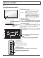
Basic Controls
Main Unit
For 50 inch and 65 inch models
Remote control
sensor
Power Indicator
The Power Indicator will light.
• Power-OFF .... Indicator not illuminated (The unit will still
consume some power as long as the power
cord is still inserted into the wall outlet.)
• Standby ........ Red
Orange (When “Slot power” is set to “On” and
Terminal Board is installed. See page 60)
Orange (Depending on the type of the function board
installed, when the power is supplied to the slot)
Orange (When “Control I/F Select” is set to
“DIGITAL LINK/LAN” or “Wireless Network
Standby” is set to “On”. Refer to “Operating
Instructions, Network Operations”)
• Power-ON ...... Green
• HDMI1 Power management
HDMI2 Power management
......................... Orange (With HDMI1 or HDMI2 input signal. See page 49)
* These functions are not supported by TH-50LFC70E and TH-65LFC70E.
• PC Power management (DPMS)
......................... Orange (With PC input signal. See page 49)
• DVI-D Power management
......................... Orange (With DVI input signal. See page 49)
Note:
If the power indicator is orange, power consumption during standby
is generally larger than that of when the power indicator is red.
Brightness Sensor
Detects the brightness in the viewing environment. (see page 49)
USB (VIEWER): Connect to USB memory. (see page 29)
SLOT: Terminal board (optional accessories) insert
slot (see page 4 )
Note:
The right side slot is for terminal board with 2-slot
width. The terminal board with 1-slot width does not
function when installed in the right side slot.
Enter / Aspect button
(see page 25, 34)
ENTER/
+/
VOL
-/
MENU
INPUT
Volume Adjustment
Volume Up “+” Down “–”
When the menu screen is displayed:
“+”: press to move the cursor up
“–” : press to move the cursor down
(see page 34)
MENU Screen ON / OFF
Each time the MENU button is pressed, the menu screen will switch.
(see page 34)
INPUT button (INPUT signal selection)
(see page 21)
Main Power On / Off Switch
22
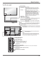
Basic Controls
For 80 inch model
Remote control
sensor
Power Indicator
The Power Indicator will light.
• Power-OFF .... Indicator not illuminated (The unit will still
consume some power as long as the power
cord is still inserted into the wall outlet.)
• Standby ........ Red
Orange (When “Slot power” is set to “On” and
Terminal Board is installed. See page 60)
Orange (Depending on the type of the function board
installed, when the power is supplied to the slot)
Orange (When “Control I/F Select” is set to
“DIGITAL LINK/LAN” or “Wireless Network
Standby” is set to “On”. Refer to “Operating
Instructions, Network Operations”)
• Power-ON ...... Green
• HDMI1 Power management
HDMI2 Power management
......................... Orange (With HDMI1 or HDMI2 input signal. See page 49)
* These functions are not supported by TH-80LFC70E.
• PC Power management (DPMS)
......................... Orange (With PC input signal. See page 49)
• DVI-D Power management
......................... Orange (With DVI input signal. See page 49)
Note:
If the power indicator is orange, power consumption during standby
is generally larger than that of when the power indicator is red.
Brightness Sensor
Detects the brightness in the viewing environment. (see page 49)
USB (VIEWER): Connect to USB memory. (see page 29)
SLOT: Terminal board (optional accessories) insert
slot (see page 4 )
Note:
The upper side slot is for terminal board with 2-slot
width. The terminal board with 1-slot width does not
function when installed in the upper side slot.
Enter / Aspect button
(see page 25, 34)
ENTER/
+
/
VOL
-
/
MENU
INPUT
Volume Adjustment
Volume Up “+” Down “–”
When the menu screen is displayed:
“+”: press to move the cursor up
“–” : press to move the cursor down
(see page 34)
MENU Screen ON / OFF
Each time the MENU button is pressed, the menu screen will switch.
(see page 34)
INPUT button (INPUT signal selection)
(see page 21)
Main Power On / Off Switch
23
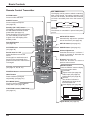
Basic Controls
Remote Control Transmitter
ACTION button
Press to make selections.
ASPECT button
Press to adjust the aspect.
(see page 25)
Standby (ON / OFF) button
The Display must rst be plugged into
the wall outlet and turned on at the
power switch (see page 19).
Press this button to turn the Display
On, from Standby mode. Press
it again to turn the Display Off to
Standby mode.
POS./SIZE button
(see page 35)
PICTURE button
(see page 38)
Sound mute On / Off
Press this button to mute the
sound.
Press again to reactivate sound.
Sound is also reactivated when
power is turned off or volume level
is changed.
N button
(see page 37, 38, 39, 43)
POSITION buttons
INPUT button
Press to select Input signal
sequentially. (see page 21)
ECO MODE (ECO)
Press to change the ECO MODE
setup status. (see page 49)
OFF TIMER button
The Display can be preset to switch to stand-by
after a xed period. The setting changes to 30
minutes, 60 minutes, 90 minutes and 0 minutes
(off timer cancelled) each time the button is
pressed.
30 min
60 min
90 min
0 min (Cancel)
When three minutes remain, “Off timer 3 min”
will ash.
The off timer is cancelled if a power interruption
occurs.
AUTO SETUP button
Automatically adjusts the position/
size of the screen. (see page 35)
SET UP button (see page 44)
SOUND button (see page 43)
Volume Adjustment
Press the Volume Up “+” or Down “–”
button to increase or decrease the
sound volume level.
R button (see page 34)
Press the R button to return to
previous menu screen.
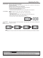
RECALL button
Press the “RECALL” button to display
the current system status.
1 Input label
2 Aspect mode (see page 25)
Audio input (see page 63)
Prole name (see page 42)
3 Off timer
The off timer indicator is
displayed only when the off
timer has been set.
4 Clock display (see page 60)
1
PC
FUNCTION buttons (FUNCTION)
(see page 51)
4:3
COMPONENT
Memory name: MEMORY2
4
10:00
Off timer
90min
Digital Zoom (see page 26)
24
2
3
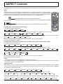
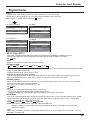
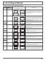
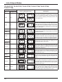
ASPECT Controls
The Display will allow you to enjoy viewing the picture at its maximum size, including wide screen cinema format
picture.
Note:
Be aware that if you put the display in a public place for commercial purposes or a public showing
and then use the aspect mode select function to shrink or expand the picture, you may be violating
the copyright under copyright law. It is prohibited to show or alter the copyrighted materials of other
people for commercial purposes without the prior permission of the copyright holder.
Press repeatedly to move through the aspect options:
For details about the aspect mode, please see “List of Aspect Modes” (page 69).
[from the unit]
ENTER/
The aspect mode changes each time the ENTER button is pressed.
[TH-50LFC70U, TH-65LFC70U, TH-80LFC70U]
For VIDEO (S VIDEO) signal input:
4:3
ZOOM
FULL
JUST
For PC signal input:
4:3
ZOOM
For SD signal input (525 (480) / 60i • 60p, 625 (575) / 50i • 50p):
4:3
ZOOM
FULL
JUST
FULL
For HD signal input [1125 (1080) / 60i • 50i • 60p • 50p • 24p • 25p • 30p • 24psF, 1250 (1080) / 50i, 750 (720) / 60p • 50p]:
4:3
H-FILL
ZOOM
FULL
JUST
With the following inputs, the aspect will be xed to “FULL” and you cannot switch it.
Miracast(TM), MEMORY VIEWER
[TH-50LFC70E, TH-65LFC70E, TH-80LFC70E, TH-50LFC70W, TH-65LFC70W, TH-80LFC70W]
For VIDEO (S VIDEO) signal input:
4:3
Zoom1
Zoom2
Zoom3
16:9
14:9
Just
For PC signal input:
4:3
Zoom
16:9
For SD signal input (525 (480) / 60i • 60p, 625 (575) / 50i • 50p):
4:3
Zoom1
Zoom2
Zoom3
16:9
14:9
Just
For HD signal input [1125 (1080) / 60i • 50i • 60p • 50p • 24p • 25p • 30p • 24psF, 1250 (1080) / 50i, 750 (720) / 60p • 50p]:
4:3
Just
4:3 Full
14:9
Zoom1
16:9
Zoom2
Zoom3
With the following inputs, the aspect will be xed to “16:9” and you cannot switch it.
Miracast(TM), MEMORY VIEWER
Notes:
• The aspect mode is memorized separately for each input terminal.
• Do not allow the picture to be displayed in 4:3 mode for an extended period, as this can cause a permanent image
retention to remain on the Display Panel.
All Aspect mode
Set “All Aspect” to “On” in Options menu to enable the extended aspect mode (page 60). When All Aspect mode, the aspect
mode of pictures is switched as follows. For details about the aspect mode, please see “List of Aspect Modes”. (page 69)
For VIDEO (S VIDEO) signal input:
4:3
Zoom1
Zoom2
Zoom
16:9
14:9
Just
For SD signal input (525 (480) / 60i • 60p, 625 (575) / 50i • 50p):
For PC signal input:
4:3
Zoom3
16:9
4:3
Zoom1
Zoom2
Zoom3
16:9
14:9
Just
For HD signal input [1125 (1080) / 60i • 50i • 60p • 50p • 24p • 25p • 30p • 24psF, 1250 (1080) / 50i, 750 (720) / 60p • 50p]:
4:3 Full
Zoom1
Zoom2
Zoom3
16:9
14:9
Just1
Just2
4:3 (1)
4:3 (2)
25
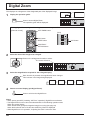
Digital Zoom
This displays an enlargement of the designated part of the displayed image.
1
Display the operation guide.
Exit
Press to access Digital Zoom.
The operation guide will be displayed.
1
During Digital Zoom, only the following buttons can be operated.
[Remote control]
OFF TIMER button
[Unit]
ENTER/
VOL button
+/
MUTE button
VOL button
VOL
-/
POSITION /
ACTION button
2
Select the area of the image to be enlarged.
Press on the enlargement location to select.
The cursor will move.
Exit
2
3
Select the magnication required for the enlarged display.
Each time this is pressed, the magnication factor changes.
This is shown in the image being displayed.
s1
4
s2
Return to normal display (quit Digital Zoom).
Press to exit from the Digital Zoom.
Notes:
• When power goes OFF (including “Off Timer” operation), Digital Zoom terminates.
• The Digital Zoom function cannot be selected while in the following operation state:
When two screen display.
When Screensaver (except for Negative image) is running (see page 47)
When the thumbnail view or le list view of Memory Viewer is displayed
• While Digital Zoom is in operation, “Adjusting Pos./Size” cannot be used.
26
s3
s4
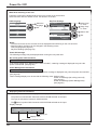
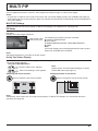
MULTI PIP
You can display two pictures, such as a video image and computer image, in a two-screen display.
Notes:
• If “Input lock” in Options menu is set to other than “Off”, two screen display function isn’t available (see page 59).
• 2k1k signals that are received with the Dual Link HD-SDI Terminal Board (TY-FB11DHD) cannot be displayed in
two-screen display.
MULTI PIP Settings
Set the functions for two-screen display in “MULTI PIP Settings” in the Setup menu. (see page 46)
PIP Mode
Pic in Pic
Displays two input images combined.
SLOT INPUT
Main screen input
Sub screen input
The following four system inputs are combined:
A Panasonic APPLICATION
B SLOT INPUT
C HDMI1/HDMI2/DVI/DIGITAL LINK/COMPONENT/PC
D VIDEO
Note:
Two screen display cannot be displayed with the same system
inputs such as HDMI1-DVI combined.
Note:
SD signal is displayed in 4:3 mode on the sub screen.
Using Two Screen Display
Set “MULTI PIP” in “MULTI PIP Settings” to “On” (see page 46).
Two screen display appears.
Using the FUNCTION button
Note:
On/Off of “MULTI PIP” switches.
Please use the “Function Button Settings” to set the
FUNCTION button (see page 51).
“MULTI PIP Settings” menu appears.
Switching Sub Screen Position
Press to switch the sub screen position.
Changing the Size of Sub Screen
Press to change the size of the sub screen.
Note:
Alternatively, “Sub screen size” and “Sub screen position” in “MULTI PIP Settings” can be used for the same
operation (see page 46).
27
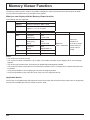
Memory Viewer Function
The Memory Viewer function makes it is possible to display the video and pictures which are stored in the USB
memory when the USB memory is inserted into the display.
What you can display with the Memory Viewer function
The following les are supported.
Picture
Video
Extension
Format
jpg/jpeg
Maximum resolution: 8000 × 8000
bmp
Maximum resolution: 8000 × 8000
support: 1, 4, 8, 16, 24, 32 bit
Extension
Video codec
Audio codec
mov
H.264/AVC
MotionJpeg
AAC
Linear PCM
avi
H.264/AVC
MotionJpeg
Mpeg4
mp3
AAC
Linear PCM
mp4
H.264/AVC
Mpeg4
AAC
Mpeg4 AAC-LC
mpg/mpeg
Mpeg2
Mpeg1 Layer2
wmv
WMV9
WMA
Video format
Audio format
Maximum:
1920 × 1080/30 fps
Maximum:
48 kHz 2 ch
(It is up to 16 kHz
stereo when the
codec is linear
PCM)
Notes:
• The maximum size of le is 2 GB.
• The maximum number of le/folder is up to 1000. If it exceeds, the folder cannot display and an error message
appears.
• You cannot play the les which are protected by Digital Rights Management (DRM).
• The maximum number of les that can hold resume information is 50. If it exceeds 50, the oldest information will
be deleted.
• It may be impossible to resume playing the le from the stopped position.
• It may be impossible to play some les even if they are in the supported format.
Applicable device
The function is compatible with USB memories sold in the market. (Devices with security feature are not supported)
Devices not formatted with FAT16 or FAT32 cannot be used.
28
Memory Viewer Function
Inserting the USB memory
Insert the USB memory to the USB (VIEWER) port on the side of the display.
USB
(VIEWER)
USB MEMORY
Notes:
• When inserting the USB memory, conrm the direction of the plug not to damage the terminal.
• Please note following points to insert and remove the USB memory.
• The indicator of the inserted USB memory will be blinking while the display is reading out the data. Do not
remove the USB memory while it is blinking.
• When using a USB memory without indicator, you cannot recognize when the display is reading out the data.
Please remove it from the display after closing the Memory Viewer function or turning off the display.
• Do not insert and remove the USB memory frequently. Remove the USB memory at least 5 seconds after
insertion. And insert at least 5 seconds after removal. The display needs some time to detect insertion or
removal of the USB memory.
Caution on handling and storing the USB memory
• Do not put USB memory or its cap within close reach of children. Swallowing it may cause suffocation.
• If the smoke or questionable odor rises, remove the USB memory from the equipment and contact the manufacturer.
• Do not put water, chemical or oil to the USB memory. It may cause short out or re.
• Do not put foreign objects or put metal objects to the USB terminal. Static electricity may cause data loss or data
corruption.
• Do not remove the USB memory from the computer or the display while the USB memory is reading out or writing
the data. It may cause data loss or data corruption.
• Do not store the USB memory in hot, humid or dusty place or near magnetized items.
Notes:
• During accessing to the USB memory, do not turn off the power or remove the USB memory because the data in
the USB memory might get damaged. During accessing, the USB memory is blinking.
• The USB memory allows you to insert or remove regardless of the power status of the display.
29
Memory Viewer Function
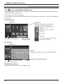
Displaying the Memory Viewer screen
Press
to select the MEMORY VIEWER input.
If “INPUT (MEMORY VIEWER)” has been assigned to a FUNCTION button, simply pressing it can switch the input
to MEMORY VIEWER. (see page 51)
The thumbnails or the le list is displayed.
You can switch the display between the thumbnail view and le list view by setting “Setup” - “Memory Viewer Settings”.
(see page 52)
Thumbnail view
Folder list
Thumbnails
Folders, pictures and videos in the folder.
The following icons will be displayed.
Moves to the upper level when
selected.
Moves to the lower level when
selected.
Picture le.
Video le.
Information of the selected le.
Remote control
operation guide
The le has a supported extension
but cannot be played.
File list view
Folder list
File list
Information of folders, pictures and videos in the folder.
Remote control operation guide
Preview of the selected le.
Exiting Memory Viewer
Exit Memory Viewer before removing the USB memory.
30
Memory Viewer Function
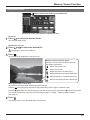
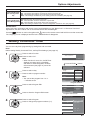
Playing the pictures
Moves between the folder list and thumbnails
Select a le in the same manner in the le list view.
Folder list
to select the desired folder.
Press
1 The
selected folder opens.
Thumbnails / File list
2 Press
to select the desired le.
Press @@ to return to the folder list.
3 Press
.
The picture will be displayed on the full screen.
Remote control operation guide
Press the remote control buttons to perform
the following operations.
Skip to the previous le
Skip to the next le
Rotate the picture clockwise (90°)
Rotate the picture counterclockwise (90°)
Stop temporarily or restart the Auto Play
Return to the thumbnail view or le list view
When [Auto Play] is set to [On]
All pictures in the same folder will be played automatically.
during Auto Play will stop the play temporarily. Press it again to restart the play.
Pressing
Pressing during Auto Play will start the play from the previous picture and pressing from the next picture.
You can set the Auto Play interval and screen-switching effect in “Setup” - ”Memory Viewer Settings”.
(see page 52)
4 Press
.
The display returns to the thumbnail view or le list view.
31
Memory Viewer Function
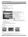
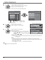
Playing the video
Select the desired le in the same manner as “Playing the pictures”. (see page 31)
Folder list
to select the desired folder.
Press
1 The
selected folder opens.
Thumbnails / File list
2 Press
Press
to select the desired le.
to return to the folder list.
3 Press
.
The video will be displayed on the full screen.
Fast-forward / Rewind / Pause indication
Remote control operation guide
Press the remote control buttons to perform
the following operations.
Rewind (3 steps)
Skip back to the previous le
(during a pause)
Fast forward (3 steps)
Skip to the next le (during a pause)
Play from the beginning
Pause / Restart playing
Return to the thumbnail view or le list
view
Time bar
Pressing
during play will rewind and
will fast-forward the video. The speed changes in three steps each
time you press the button.
When [Auto Play] is set to [On]
All videos in the same folder will be played automatically.
When the last le ends, Auto Play starts from the rst le again.
4 Press
.
The display returns to the thumbnail view or le list view.
Resume play
If you stop the video on the way and play it again, the play starts from the stopped position.
The video is
being played
The screen returns to the
thumbnail view or le list view
The play starts from the
last stopped position
Notes:
• The resume function is enabled when [Auto Play] is set to [Off]. (see page 52)
• The resume position is held until the display is turned off or the USB memory is disconnected.
Up to 50 les can hold the resume position.
32
Using Miracast(TM)
The function allows the image shown on the smartphone or tablet device to be sent and displayed on the display.
the Miracast(TM) input.
1 Select
The display switches to the [Miracast(TM)] screen and the standby screen will be displayed.
Start the Miracast application on the Miracast-compatible device or computer
2 Connect
the device of the name shown on the display.
The name of the Miracast application and how to start it may differ depending on the device model.
For how to use the Miracast application, see the instruction manual of your device.
Select “OK” in the connected device authentication screen
3 The
image on the connected device will be displayed.
Notes:
• This function can be used with Miracast-compatible Android devices and WiDi compatible computers.
• The Miracast function will be disabled if “Wireless LAN” of “Network Settings” is set to “Off”.
• If [Display Name] includes a space, the characters after the space may not be displayed on some device models.
• If you have any problem in Miracast connection, see “When using Miracast” on page 68.
33
On-Screen Menu Displays
Remote Control
Unit
1 Display the menu screen.
ENTER/
Press to select.
(Example: Picture menu)
+
/
VOL
-
/
MENU
2 Select the item.
Select.
Picture
Normalise
Press.
ENTER/
Press several times.
Press.
Normal
Normal
Picture Mode
Backlight
+
100
Contrast
100
Brightness
50
Colour
50
Hue
50
Sharpness
5
White balance
/
VOL
-
Select.
/
Normal
Advanced settings
FRAME CREATION
Max
Memory save
Memory load
Memory edit
(Example: Picture menu)
Set.
3 Set.
ENTER/
+
/
VOL
4 Exit the menu.
Press.
-
/
+
/
Adjust.
VOL
Press.
-
Press
to return to the
previous menu.
MENU
/
Press several times.
Menu display list
Note: Menu that cannot be adjusted is grayout. Adjustable menu changes depending on signal, input and menu setting.
Picture menu
Setup menu
Pos./Size menu
Sound menu
Setup
Picture
Normalise
Normal
Normal
Picture Mode
Backlight
Contrast
100
Brightness
50
Colour
50
Hue
50
Sharpness
5
White balance
Normalise
Network Settings
Auto Setup
Memory Viewer Settings
H-Pos
0
Sound Mode
H-Size
0
Bass
0
V-Pos
0
Mid
0
V-Size
0
Treble
0
Dot Clock
0
Balance
0
Clock Phase
0
Surround
Clamp Position
0
Audio Out (PIP)
Signal
100
Screensaver
ECO Mode settings
Input label
Function Button Settings
On/Off Timer Settings
Normal
Advanced settings
Day/Time Settings
Component/RGB-in select
RGB
Monitor Out
FRAME CREATION
Memory save
Memory load
Memory edit
see page 38-42
34
Max
Sound
Pos./Size
MULTI PIP Settings
Normalise
Normal
1:1 Pixel Mode
Off
No activity power off
Disable
Menu Display Duration
30 S
OSD Brightness
5
OSD Language
English (UK)
see page 44-57
Normal
Speaker
see page 35-37
Off
Internal
Normal
Off
Main
Left Channel
Channel 1
Right Channel
Channel 1
Sound Out
Off
Level Meter
Off
see page 43
Adjusting Pos./Size
1
Press to display the Pos./Size menu.
Pos./Size
Normalise
2
3
Press to select the menu to adjust.
Normal
Auto Setup
Press to adjust the menu.
H-Pos
0
H-Size
0
V-Pos
0
V-Size
0
Dot Clock
0
Clock Phase
0
Clamp Position
0
1:1 Pixel Mode
4
Press to exit from adjust mode.
Off
Note:
Unadjustable items are grayed
out.
Adjustable items differ depending
on the input signal and the
display mode.
Notes:
• Pos./Size cannot be adjusted with two screen display.
• Adjustment details are memorized separately for different input signal formats (Adjustments for component signals are
memorized for 525 (480) / 60i · 60p, 625 (575) / 50i · 50p, 1125 (1080) / 60i · 50i · 60p · 50p · 24p · 25p · 30p · 24psF,
1250 (1080) / 50i, 750 (720) / 60p · 50p each, and RGB/PC/Digital signals are memorized for each frequency.)
• If a “Cue” or “Rew” signal from a VCR or DVD player is received, the picture position will shift up or down. This picture
position movement cannot be controlled by the Picture Pos./Size function.
Auto Setup
When inputting a PC signal as an example, “H-Pos/V-Pos”, “H-Size/V-Size”, “Dot Clock” and “Clock
Phase” are automatically corrected.
This setting is enabled under the following conditions:
• When inputting an analog signal (Component/PC):
This setting is enabled if “Component/RGB-in select” (see page 54) in Setup menu is “RGB”.
• When inputting a digital signal (HDMI/DVI):
A PC format signal enables this setting.
When the signal is not PC format, this setting is enabled only if “Over Scan” (see page 36) is “Off” or
“1:1 Pixel Mode” (see page 37) is “On”. “H-Size/V-Size” is not automatically adjusted.
This setting will be invalid and will not work under the following conditions:
• When one of the following inputs is selected
Miracast(TM), MEMORY VIEWER, Panasonic APPLICATION
• When VIDEO signal input
• During two screen or Digital Zoom.
• Aspect is set to “Just”
• “Display size” in the Options menu (see page 59) is set to “On”
Using Remote Control
When
on the remote control is pressed, “Auto Setup” will be executed.
When Auto Setup does not work, “Invalid” is displayed.
Auto mode
When the “Auto Setup“ is set to “Auto” in the Options menu (see page 60), automatic position adjustment starts:
• When the display power is turned ON.
• When the input signal is switched.
35
Adjusting Pos./Size
Notes:
• If the dot clock frequency of an analog signal is 162 MHz or higher, “Dot Clock” and “Clock Phase”
cannot be automatically corrected.
• When digital signal input, Dot Clock and Clock Phase cannot be made.
• Auto Setup may not work when a cropped or dark image is input. In such case, switch to a bright
image with borders and other objects are clearly shown, and then try auto setup again.
• Depending on the signal, out of alignment may occur after Auto Setup. Carry out ne tuning for the
position/size as required.
• If Auto Setup cannot set properly for vertical frequency 60Hz XGA signal (1024×768@60Hz,
1280×768@60Hz, and 1366×768@60Hz), pre-selecting the individual signal in “XGA Mode” (see
page 55) may results in correct Auto Setup.
• Auto Setup does not work well when a signal such as additional information is superimposed out
of valid image period or intervals between synchronizing and image signals are short, or for image
signal with tri-level synchronizing signal added.
• If Auto Setup cannot adjust correctly, select “Normalise” once and press ACTION ( ), then adjust
Pos./Size manually.
H-Pos
Adjust the horizontal position.
V-Pos
Adjust the vertical position.
H-Size
Adjust the horizontal size.
V-Size
Adjust the vertical size.
Dot Clock
(During Component/PC input signal)
Periodic striped pattern interference (noise) may occur when a striped pattern is displayed. If this happens,
adjust so that any such noise is minimized.
Clock
Phase
(During Component/PC input signal)
Eliminate the ickering and distortion.
Over scan Turn image over scan On/Off.
Congurable signals are as follows:
525i, 525p, 625i, 625p, 750/60p, 750/50p (Component Video, RGB, DVI, SDI, HDMI)
On
Off
Notes:
• When “Off” is set, “H-Size” and “V-Size” cannot be adjusted.
• When the “Display size” is set to “On” in the Options menu, this setting will be invalid. (see page 59)
36
Adjusting Pos./Size
Clamp Position
(During Component/PC input signal)
Adjusts the clamp position when black parts of the image have no detail due to underexposure
or are tinged with green.
Optimum value for Clamp Position adjustment
When black parts have no detail due to underexposure (blackout)
Value that causes least blackout is the optimum.
When black parts are tinged with green
Value that cancels the greenishness without causing blackout is the optimum.
1:1 Pixel Mode
Adjusts the display size when 1125i, 1125p or 1250i signal is input.
Notes:
• Select On when you would like to replay 1920 × 1080 input signal.
• Applicable input signal;
1125 (1080) / 50i · 60i · 24psF · 24p · 25p · 30p · 50p · 60p, 1250 (1080) / 50i
• Select Off when ickering is shown around the image.
• H-Size and V-Size cannot be adjusted when On is selected.
Off
On
1:1 Pixel Mode
When the input signal is a 2k1k signal (2048 × 1080 / 24p, 2048 × 1080 / 24psF), the display size
(2k1k)
is adjusted as follows.
(For 2k1k signals)
Off
On (Left)
On (Center)
On (Right)
Note:
2k1k signals can only be received when the Dual Link HD-SDI Terminal Board (TY-FB11DHD) is installed.
Helpful Hint (
/
Normalise
Normalisation)
While the Pos./Size display is active, if either the N button on the remote control is pressed at any time or the ACTION
( ) button is pressed during “Normalise”, then all adjustment values are returned to the factory settings.
37
Picture Adjustments
1
2
Press to display the Picture menu.
Select to adjust each item.
Press to select the menu to adjust.
Select the desired level by looking at the picture behind the menu.
Note:
Menu that cannot be adjusted is grayout. Adjustable menu changes depending on signal,
input and menu setting.
Picture
Normalise
Press “ ” or “ ” button to switch between modes.
Normal
Normal*
Normal
Picture Mode
Backlight
100
Contrast
100
Brightness
50
Colour
50
Hue
50
Sharpness
5
Dynamic
Cinema
White balance
Normal
Advanced settings
FRAME CREATION
Max
Press to enter
Advanced settings.
Advanced settings
Enables ne picture adjustment at a professional
level (see next see page).
Normal
For viewing in standard (evening lighting) environments.
This menu selects the normal levels of Brightness
and Contrast.
* In “ENGLISH (US)” OSD language, this is
displayed as “STANDARD”.
Dynamic
For viewing in brighter environments.
This menu selects higher than normal levels of
Brightness and Contrast.
Cinema
For use in viewing tone-focused pictures with
brightness reduced.
Notes:
• If you would like to change the picture and colour of
the selected Picture menu to something else, adjust
using the items in the Picture menu. (see next page)
• In “ENGLISH (US)” OSD language, the “Picture
Mode” is displayed as “PICTURE MENU”.
Advanced settings
Normalise
Normal
Press “ ” or “ ” button to switch between modes.
0
Input level
2.2
Gamma
W/B High R
50
W/B High G
50
W/B High B
50
W/B Low R
50
W/B Low G
50
W/B Low B
50
Normal (9300K)
Min
Helpful Hint (
Mid
/
Warm (6500K)
• In “ENGLISH (US)” OSD language, the “White
balance” is displayed as “COLOR TEMP”.
FRAME CREATION
Improves motion picture quality by reducing motion blur.
Press the left or right button to switch between
modes.
Off
Cool (11500K)
Normalise
Max
Notes:
• The mode is memorized per input terminal.
• Even if “Normalise” is selected, the Normal setting
will not be restored.
• The picture and menu will disappear for a moment
if you switch the mode to Off, or switch from Off to
another mode.
Normalisation) (except “FRAME CREATION”)
While the “Picture” menu is displayed, if either the N button on the remote control is pressed at any time or the
ACTION ( ) button is pressed during “Normalise”, then all adjustment values are returned to the factory settings.
38
Picture Adjustments
Item
Backlight
Contrast*
Brightness
Colour
Hue
Sharpness
Effect
Adjustments
Darker
Brighter
Adjusts luminance of the back
light.
Less
More
Selects the proper brightness
and density for the room.
Darker
Brighter
Less
More
Reddish
Greenish
Less
More
Adjusts for easier viewing of
dark pictures such as night
scenes and black hair.
Notes:
• You can change the level of each function
(Contrast, Brightness, Colour, Hue,
Sharpness) for each Picture Mode.
• The setting details for Normal, Dynamic
and Cinema respectively are memorized
separately for each input terminal.
• “Backlight” can be adjusted when “ECO
Mode” is set to “Custom” and “Power save”
to “Off”. (see page 49)
Adjusts colour saturation.
Adjusts for nice skin colour.
Adjusts picture sharpness.
* In “ENGLISH (US)” OSD language, this is displayed as “PICTURE”.
Advanced settings
Item
Input level
Effect
Details
Less
More
Down
Up
W/B High
R
Less
More
W/B High
G
Less
More
W/B High
B
Less
More
Less
More
Less
More
Less
More
Gamma
W/B Low R
W/B Low G
W/B Low B
Adjustment of parts which are extremely bright and hard to see.
S Curve
2.0
2.2
2.6
Adjusts the white balance for light red areas.
Adjusts the white balance for light green areas.
Adjusts the white balance for light blue areas.
Adjusts the white balance for dark red areas.
Adjusts the white balance for dark green areas.
Adjusts the white balance for dark blue areas.
Notes:
• Advanced settings cannot be adjusted with two screen display.
• Carry out “W/B” adjustment as follows.
1. Adjust the white balance of the bright sections using the “W/B High R”, “W/B High G” and “W/B High B”
settings.
2. Adjust the white balance of the dark sections using the “W/B Low R”, “W/B Low G” and “W/B Low B” settings.
3. Repeat steps 1 and 2 to adjust.
Steps 1 and 2 affect each other’s settings, so repeat each step in turn to make the adjustment.
• The adjustment values are memorized separately for each input terminal.
• The adjustment range values should be used as an adjustment reference.
Helpful Hint (
/
Normalise
Normalisation)
On the remote control unit, while the “Advanced settings” menu is displayed, if either the N button is pressed at any time or
the ACTION ( ) button is pressed during “Normalise”, then all adjustment values are returned to the factory settings.
39
Picture Proles
Up to 8 combinations of picture adjustment values (in the Picture menu and Advanced settings) can be stored in the
display memory as proles and applied as needed, for a convenient way to enjoy your preferred picture settings.
Picture
Normalise
Normal
Normal
Picture Mode
Backlight
100
Contrast
100
Brightness
50
Colour
50
Hue
50
Sharpness
5
White balance
Normal
Advanced settings
Picture
FRAME CREATION
Max
Normalise
Memory load
Memory edit
Normal
Normal
Picture Mode
Save proles (page 41)
Memory save
Load proles (page 42)
Edit proles (page 42)
Backlight
100
Contrast
90
Brightness
50
Colour
60
Hue
50
Sharpness
5
White balance
Normal
Advanced settings
FRAME CREATION
Max
Save proles
Edit the prole
Delete or rename
the prole
Save the picture
adjustment values in
the MEMORY1 prole
MY PICTURE
MEMORY2
MEMORY3
MEMORY4
MEMORY1
MEMORY2
MEMORY3
MEMORY4
MEMORY8
MEMORY8
Load the prole
Custom picture
Original picture
Picture
Picture
Normalise
Normalise
Normal
Normal
Picture Mode
Normal
Normal
Picture Mode
Backlight
100
Backlight
100
Contrast
50
Contrast
90
Brightness
50
Brightness
50
Colour
50
Colour
60
Hue
50
Hue
50
Sharpness
0
Sharpness
5
White balance
Normal
FRAME CREATION
White balance
Normal
Advanced settings
Advanced settings
40
Apply the MEMORY1
prole
Max
FRAME CREATION
Max
Picture Proles
Saving proles
Follow these steps to save picture adjustment values as proles.
1
Specify the picture quality in the Picture menu and
Advanced settings. (see page 38, 39)
2
In the Picture menu, select “Memory save”.
5
1 select
Memory save
Memory load
2 access
Memory edit
3
Enter a name for the prole.
[Entering prole names]
Prole names can be up to 40 characters.
To enter text, select characters in the on-screen
keyboard.
Edit the default prole name in the text box as
desired.
Memory name input
1 select
MEMORY1
A B C
N O P
a b c
n o p
0 1 2
!
” #
_ `
|
Select a prole name for saving the picture adjustment
values.
1 select
Memory save
1. [
2. [
]
MEMORY1
]
MEMORY2
3. [
4. [
]
]
MEMORY3
5. [
6. [
]
MEMORY5
]
MEMORY6
7. [
8. [
]
MEMORY7
]
MEMORY8
F
S
f
s
5
&
>
G
T
g
t
6
’
(
H
U
h
u
7
)
I
V
i
v
8
+
[
J
W
j
w
9
–
]
K
X
k
x
L M All delete
Y Z
Delete
l m
y z
Space
/ = ? @ \
ˆ
{
}
,
.
;
:
Cancel
2 set
Example: Specifying “MY PICTURE”
MEMORY4
1
Select “All delete”.
MEMORY1
All text is deleted.
To delete individual characters, select “Delete”.
2
Select “M”.
M
Select “Ok”.
Repeat this process to enter the next character.
1 select
Memory save
3
Save the adjusted value in ”MEMORY1”
Ok
E
R
e
r
4
%
<
Ok
2 set
“” appears for a prole in which the picture
adjustments have already been saved.
4
D
Q
d
q
3
$
~
Cancel
2 set
Select “Y”.
MY
4
Select “Space”.
MY
6
When you nished entering the prole name, select
“Ok”.
To cancel saving the prole, select “Cancel”.
Memory name input
1 select
MY PICTURE
A B C
N O P
a b c
n o p
0 1 2
!
” #
_ `
|
D
Q
d
q
3
$
~
E
R
e
r
4
%
<
Ok
F
S
f
s
5
&
>
G
T
g
t
6
’
(
H
U
h
u
7
)
I
V
i
v
8
+
[
J
W
j
w
9
–
]
K
X
k
x
L M All delete
Y Z
Delete
l m
y z
Space
/ = ? @ \
ˆ
{
}
,
.
;
:
Cancel
2 set
41
Picture Proles
Loading proles
Load proles and apply the picture adjustment values to the display as follows.
Note:
Loaded proles are stored in memory according to the selected input terminal. (see page 21)
1
In the Picture menu, select “Memory load”.
1 select
2
Memory save
Memory load
2 access
Memory edit
Select the prole to load.
1 select
Memory load
1. [
2. [
]
MEMORY1
]
MEMORY2
3. [
]
MEMORY3
2 set
PC
16:9
When prole is being loaded,
prole name is displayed.
Memory name: MEMORY2
Editing proles
Delete or rename proles as follows.
<Deleting proles>
1
<Renaming proles>
In the Picture menu, select “Memory edit”.
1 select
1
In the Picture menu, select “Memory edit”.
1 select
Memory save
Memory save
Memory load
2
Memory load
2 access
Memory edit
Select “Memory delete”.
1 select
Memory edit
2
3
Select the prole to delete.
To delete all proles, select “All delete”.
1 select
Memory delete
1. [
2. [
]
MEMORY1
]
MEMORY2
3. [
]
2 set
MEMORY3
4
All delete
1 select
Memory edit
2 set
Memory name change
Memory name change
3
Select “Memory name change”.
Memory delete
2 set
Memory delete
2 access
Memory edit
Select the prole to rename.
1 select
Memory name change
1. [
]
MEMORY1
2. [
]
MEMORY2
3. [
]
MEMORY3
2 set
Enter a name for the prole.
Entering prole names
page 41
1 select
Memory name input
4
Select “Ok”.
EMORY1
M
A B C D E
N O P Q R
a b c d e
n o p q r
0 1 2 3 4
! ” # $ %
_ `
| ~ <
Ok
1 select
Memory delete
Delete the ”MEMORY1” data.
Ok
Cancel
2 set
5
F
S
f
s
5
&
>
G
T
g
t
6
’
(
H
U
h
u
7
)
I
V
i
v
8
+
[
J
W
j
w
9
–
]
K
X
k
x
L M All delete
Y Z
Delete
l m
y z
Space
/ = ? @ \ ˆ
{ } ,
.
;
:
Cancel
2 set
When you nished entering the prole name, select
“Ok”.
To cancel renaming the prole, select “Cancel”.
Ok
Cancel
1 select
2 set
42
Sound Adjustment
1
2
Sound
Press to display the Sound menu.
Normalise
Normal
Speaker
Select to adjust each item.
Internal
Sound Mode
Press to select the menu to adjust.
Select the desired level by listening to the sound.
Normal
Bass
0
Mid
0
Treble
0
Balance
0
Surround
Off
Audio Out (PIP)
3
Main
Press to exit from adjust mode.
Item
Speaker
Sound Mode
Bass
Mid
Treble
Balance
Surround
Details
Select the audio output.
Internal: Internal speakers
External: External speakers
Normal: Emits the original sound.
Dynamic: Accentuates sharp sound.
Clear: Attenuates human voice.
Adjusts low pitch sounds.
Adjusts normal sounds.
Adjusts high pitch sounds.
Adjusts left and right volumes.
Select On or Off.
Main: Selects main picture sound.
Sub: Selects PIP frame sound.
VIDEO
PC
VIDEO
PC
A
Audio Out (PIP)
A
Musical note is displayed on right side of the audio
output screen label.
Note: Bass, Mid, Treble and Surround settings are memorized separately for each Sound Mode.
Helpful Hint (
/
Normalise
Normalisation)
While the “Sound” menu is displayed, if either the N button on the remote control is pressed at any time or the
ACTION ( ) button is pressed during “Normalise”, then all adjustment values are returned to the factory settings.
SDI Sound Output
This menu is available only when selecting a slot that any of the following terminal boards is installed:
HD-SDI Terminal Board with audio (TY-FB10HD) or Dual Link HD-SDI Terminal Board (TY-FB11DHD)
Left Channel
Channel 1
Right Channel
Channel 1
Sound Out
Off
Level Meter
Off
Note:
This menu is unavailable when two screen
display mode is active.
Item
Left Channel
Right Channel
Details
Channel 1 to Channel 16
Selects left audio channel.
Channel 1 to Channel 16
Selects right audio channel.
Sound Out
On
Off
On: Enables audio output.
Off: Disables audio output.
Level Meter
Off
1-8ch
9-16ch
Sets audio channels to show in the audio level meter.
8 channels are displayed in the audio level meter; 4 channels
each on both right and left sides of the display.
Off: Hides the audio level meter.
1-8ch: Displays the audio level meter (1-8ch)
9-16ch: Displays the audio level meter (9-16ch)
43
Setup menu
1
Press to display the Setup menu.
Setup
Press to select the menu to adjust.
2
MULTI PIP Settings
Network Settings
Memory Viewer Settings
Signal
Screensaver
ECO Mode settings
Press to adjust the menu.
3
Input label
Function Button Settings
On/Off Timer Settings
Day/Time Settings
Component/RGB-in select
Monitor Out
4
Press to exit from adjust mode.
No activity power off
Menu Display Duration
Press
to return to the previous menu.
RGB
Off
Disable
30 S
OSD Brightness
5
OSD Language
English (UK)
Setup menu screen
Setup
Page 46
MULTI PIP Settings
Network Settings
Network Settings
Memory Viewer Settings
Signal
Screensaver
ECO Mode settings
Input label
Function Button Settings
On/Off Timer Settings
Day/Time Settings
Component/RGB-in select
Monitor Out
No activity power off
Menu Display Duration
RGB
Off
Disable
30 S
OSD Brightness
5
OSD Language
English (UK)
44
Page 52
Page 55
Page 47
Page 49
Page 50
Page 51
Page 45
Page 45
Page 54
Page 52
Page 53
Page 53
Page 53
Page 53
Set this to connect the Display to a computer via a network.
For details of PJLink and Network, refer to “Operating
Instructions, Network Operations”.
Day/Time Settings / On/Off Timer Settings
The timer can switch the Display On or Off.
Before attempting Timer Set, conrm the Time and adjust if necessary.
Then set POWER ON Time / POWER OFF Time.
1
2
Press to display the Setup menu.
Press to select On/Off Timer Settings or Day/Time Settings.
Press to display the On/Off Timer Settings screen or
Day/Time Settings screen.
Day/Time Settings
1
2
Press to select Day or Time.
Day/Time Settings
Press to setup Day or Time.
Set
button: Forward
Day
button: Back
Time
Notes:
• Pressing “ ” or “ ” button once changes Time
1 minute.
• Pressing “ ” or “ ” button continuously changes Time by 15 minutes.
Time
MON 99:99
MON
99:99
Press to select Set.
Press to store Day/Time Settings.
Notes:
• Set cannot be selected unless Time is set.
• Unless setting the present time other than “99:99”, “Day” and “Time” cannot be set.
• The settings of “Day” and “Time” are reset when leaving the display turned off for
about 7 days for the following reasons:
Pressing
switch of the unit to turn off the display.
Disconnecting the AC cord.
Interruption of power supply.
On/Off Timer Settings
1
2
Press to select POWER ON Time / POWER OFF
On/Off Timer Settings
Time.
Press to setup POWER ON Time / POWER OFF
POWER ON Function
Time.
POWER ON Time
button: Forward
POWER OFF Function
button: Back
POWER OFF Time
Notes:
• Pressing “ ” or “ ” button once changes POWER
ON Time / POWER OFF Time 1 minute.
• Pressing “ ” or “ ” button continuously changes
POWER ON Time / POWER OFF Time by 15 minutes.
Time
99:99
Off
0:00
Off
0:00
Press to select POWER ON Function/POWER OFF
Function.
Press to select On.
Note: Timer function will not work unless “Time” is set.
45
MULTI PIP Settings
Set the two screen display function.
MULTI PIP (page 27)
Two screen display function
Select “MULTI PIP Settings” in “Setup” menu and press
button.
MULTI PIP Settings
MULTI PIP
On
Main input
COMPONENT
Sub input
VIDEO
1
Sub screen size
Sub screen position
Lower right
Swap
MULTI PIP
Set this “ON” to have two screen display. Various settings such as “PIP Mode” can be set.
Main input
Sets the input image for the main screen.
Sub input
Sets the input image for the sub screen.
Sub screen size
1 (small) - 4 (large): Sets the size of the sub screen.
Sub screen position
Sets the display position of the sub screen.
Swap
Swap the main and sub screens.
46
Screensaver (For preventing image retention)
Do not display a still picture, especially in 4:3 mode, for any length of time.
If the display must remain on, a Screensaver should be used.
1
Select “Screensaver” in “Setup” menu and press
2
Function selection
button.
Screensaver
Time
Press to select Function.
10:00
Start
Press to select the desired function.
Scrolling bar only
Negative image
White screen
Overlay scrolling bar
Function
Scrolling bar only
Mode
Off
Side panel
Off
Wobbling
Off
Negative image : Negative image will be displayed on the screen.
Scrolling bar only : A white bar will scroll from left to right. The image won't be displayed.
Overlay scrolling bar : The brightness of the image will be decreased and a white bar will scroll
on it.
White screen
: The whole screen will be white.
Note: Overlay scrolling bar is not effective during two screen display.
3
Mode selection
Press to select Mode.
Press to select each
mode items.
Standby after SCR Saver: Operates while Screensaver duration, and
display enters standby mode.
: Operates when Start is selected and the
On
ACTION ( ) button is pressed.
Off
Interval
: Operates when Periodic Time and Operating
Time are setup and those times arrive.
Time Designation : Operates when Start Time and Finish Time
are setup and those times arrive.
4
Start setting
When the Mode is set to On, press to select Start.
Press to start Screensaver.
The menu screen will disappear and the Screensaver will be activated. To stop the
Screensaver under On, press the R button or any buttons on the main unit.
Note: When the display is turned off, the Scrensaver will be deactivated.
47
Screensaver (For preventing image retention)
Setup of Screensaver Time
After selecting Time Designation, Interval or Standby after SCR Saver, the relevant Time Setup will become available
for selection and the Operating Time may be set. (Time cannot be set when “Mode” is “On” or “Off”.)
Press to select Start Time / Finish Time
(when Time Designation is selected).
Press to select Periodic Time / Operating Time
(when Interval is selected).
Press to select Screensaver duration
(when Standby after SCR Saver is selected).
Press to setup.
button: Forward
button: Back
Screensaver
Time
15:00
Start
Function
Scrolling bar only
Mode
Time Designation
Start Time
6:15
Finish Time
12:30
Screensaver
Time 15:00
Notes:
• Pressing “ ” or “ ” button once changes the Time 1 minute.
[However, switching occurs every 15 minutes when Periodic Time is
selected.]
• Pressing “ ” or “ ” button continuously changes the Time by 15
minutes.
• “Screensaver duration” of the “Standby after SCR Saver” can be set from
0:00 to 23:59. When this is set to “0:00”, “ Standby after SCR Saver” will
not be activated.
Note: Timer function will not work unless “Time” is set.
Start
Function
Mode
12:00
Operating Time
3:00
Screensaver
Time
15:00
Start
Function
Scrolling bar only
Mode
Standby after SCR Saver
Side panel
side panel
Do not display a picture in 4:3 mode for an extended period,
as this can cause an image retention to remain on the side
panels on either side of the display eld.
To reduce the risk of such an image retention, illuminate
the side panels.
4:3 Screen
Display
Off:
Low:
Mid:
High:
Interval
Periodic Time
Screensaver duration
This function may be applicable to the non-picture area.
Scrolling bar only
6:15
image
retention
Darken both ends.
Make it dark gray.
Make it gray.
Make it light gray.
Note:
To reduce the occurrence of image retention, set the Side panel to High.
Wobbling
Automatically shifts the display image (therefore unnoticeable to the eye) to prevent image retention of sharper contour
of image.
Note:
When this function is operating, part of the screen may appear to be missing.
48
ECO Mode settings
Select “ECO Mode settings” in “Setup” menu and press
button.
ECO Mode
ECO Mode settings
ECO Mode
Custom
Power save
Off
HDMI1 Power management
Off
HDMI2 Power management
Off
PC Power management
Off
DVI-D Power management
Off
No signal power off
Disable
Custom: The menu of power consumption reduction is individually set.
On: The following xed values are set to the menu of power consumption
reduction. Individual setting is not available.
Power save: On
DVI-D Power management: On
HDMI1 Power management: On No signal power off: Enable
HDMI2 Power management: On
PC Power management: On
Using Remote Control
When
is pressed, the “ECO
ECO Mode
On
Mode” setting changes.
Custom settings
The menu of the power consumption reduction is individually set. This setting is enabled when “ECO Mode” is set
to “Custom”.
Power save
This function adjusts the brightness of the backlight to reduce power consumption.
Off: This function does not operate.
On: Backlight brightness is reduced.
Sensor: The backlight brightness is automatically adjusted according to the viewing environment.
Note:
When this function is set to “On” or “Sensor”, the “Backlight” setting in the Picture menu is disabled.
[TH-50LFC70U, TH-65LFC70U, TH-80LFC70U, TH-50LFC70W, TH-65LFC70W and TH-80LFC70W]
HDMI1 Power management, HDMI2 Power management
When this function is set to On, it operates under the following conditions to turn the power on or off automatically.
When no pictures (sync signal) are detected for 60 or so seconds during HDMI1 or HDMI2 signal input:
Power is turned off (standby); the power indicator lights up orange.
When pictures (sync signal) are subsequently detected:
Power is turned on; the power indicator lights up green.
Note:
This function is not supported by TH-50LFC70E, TH-65LFC70E and TH-80LFC70E.
PC Power management
When this function is set to On, it operates under the following conditions to turn the power on or off automatically.
When no pictures (HD/VD sync signals) are detected for 60 or so seconds during PC signal input:
Power is turned off (standby); the power indicator lights up orange.
When pictures (HD/VD sync signals) are subsequently detected:
Power is turned on; the power indicator lights up green.
Note:
This function is effective when “Sync” is set to “Auto”, “Component / RGB-in select” is set to “RGB” and during normal viewing.
DVI-D Power management
When this function is set to On, it operates under the following conditions to turn the power on or off automatically.
Standard mode
When no pictures (sync signal) are detected for 60 or so seconds during DVI signal input:
Power is turned off (standby); the power indicator lights up orange.
When pictures (sync signal) are subsequently detected:
Power is turned on; the power indicator lights up green.
Low power mode
When +5V DC in DVI-D IN terminal or pictures (sync signal) are not detected for about 60 seconds with DVI input:
Power is turned off (standby); the power indicator lights up orange.
When +5V DC or pictures (sync signal) are subsequently detected:
Power is turned on; the power indicator lights up green.
In the Standard mode, power consumption during sleep is higher than that in the Low power mode.
You can switch the Standard mode/Low power mode in “DVI Power management mode” of the Options menu. (see page 60)
Notes:
• This function is invalid during input from DVI-D Terminal Board (TY-FB11DD).
• Depending on the type of terminal board equipped, this function may be invalid.
No signal power off
Equipment power supply is turned Off when there is no signal.
When this is set to “Enable”, the power supply of the unit goes Off 10 minutes after the input signals stop.
• For MEMORY VIEWER input, it is judged as no signal when a USB memory is not connected.
49
Customizing the Input labels
This function can change the label of the Input signal to be displayed. (see page 21)
Select “Input label” in “Setup” menu and press
button.
Input label
HDMI1
HDMI2
SLOT INPUT
VIDEO
COMPONENT
HDMI1
HDMI2
SLOT INPUT
VIDEO
COMPONENT
PC
PC
DVI
DVI
DIGITAL LINK
Miracast(TM)
DIGITAL LINK
Miracast(TM)
Panasonic APPLICATION
Panasonic APPLICATION
MEMORY VIEWER
MEMORY VIEWER
Image input
[HDMI1]
Input label
HDMI1 / DVD1 / DVD2 / DVD3 / DVD4 / Blu-ray1 / Blu-ray2 / Blu-ray3 / Blu-ray4 / CATV /
VCR / STB / (Skip)
[HDMI2]
HDMI2 / DVD1 / DVD2 / DVD3 / DVD4 / Blu-ray1 / Blu-ray2 / Blu-ray3 / Blu-ray4 / CATV /
VCR / STB / (Skip)
[SLOT INPUT]*1
SLOT INPUT / DVD1 / DVD2 / DVD3 / DVD4 / Blu-ray1 / Blu-ray2 / Blu-ray3 / Blu-ray4 /
CATV / VCR / STB / (Skip)
[VIDEO]
VIDEO / DVD1 / DVD2 / DVD3 / DVD4 / Blu-ray1 / Blu-ray2 / Blu-ray3 / Blu-ray4 / CATV /
VCR / STB / (Skip)
[COMPONENT]*2
COMPONENT / DVD1 / DVD2 / DVD3 / DVD4 / Blu-ray1 / Blu-ray2 / Blu-ray3 / Blu-ray4 /
CATV / VCR / STB / (Skip)
[PC]
PC / DVD1 / DVD2 / DVD3 / DVD4 / Blu-ray1 / Blu-ray2 / Blu-ray3 / Blu-ray4 / CATV /
VCR / STB / (Skip)
[DVI]
DVI / DVD1 / DVD2 / DVD3 / DVD4 / Blu-ray1 / Blu-ray2 / Blu-ray3 / Blu-ray4 / CATV /
VCR / STB / (Skip)
[DIGITAL LINK]
DIGITAL LINK / (Skip)
[Miracast(TM)]
Miracast(TM) / (Skip)
[Panasonic APPLICATION] Panasonic APPLICATION / (Skip)
[MEMORY VIEWER]
MEMORY VIEWER / (Skip)
(Skip): The INPUT button press will skip its input.
*1 “SLOT INPUT” is displayed when a Terminal Board is installed.
*2 “COMPONENT” may be displayed as “RGB” depending on the setting of “Component/RGB-in select”. (see page 54)
When a Terminal Board with dual input terminals is installed
“SLOT INPUT” is displayed as “SLOT INPUT A” and “SLOT INPUT B” and independent settings are available.
[SLOT INPUT A]
SLOT INPUT A / DVD1 / DVD2 / DVD3 / DVD4 / Blu-ray1 / Blu-ray2 / Blu-ray3 / Blu-ray4 /
CATV / VCR / STB / (Skip)
[SLOT INPUT B]
SLOT INPUT B / DVD1 / DVD2 / DVD3 / DVD4 / Blu-ray1 / Blu-ray2 / Blu-ray3 / Blu-ray4 /
CATV / VCR / STB / (Skip)
When a Terminal Board with xed display (such as Tuner Board) is installed
Only xed display and (Skip) are available as Input label of “SLOT INPUT”.
[SLOT INPUT]
50
xed display / (Skip)
Function Button Settings
Set the functions that operates when
is pressed.
Select “Function Button Settings” in “Setup” menu and
press
button.
Function Button Settings
Function Button 1
INPUT (Miracast(TM))
Function Button 2
INPUT (MEMORY VIEWER)
Function Button Guide
• Function Button 1, Function Button 2
The following functions are set to the FUNCTION button.
On
Note:
Factory settings are as follows.
FUNCTION1 button: INPUT (Miracast(TM))
FUNCTION2 button: INPUT (MEMORY VIEWER)
ECO Mode settings / Signal / On/Off Timer Settings / MULTI PIP Settings
The menu is displayed. (Example: ECO Mode settings)
ECO Mode settings
ECO Mode
Custom
Power save
Off
HDMI1 Power management
Off
HDMI2 Power management
Off
PC Power management
Off
DVI-D Power management
No signal power off
Pressing the FUNCTION button clears the menu.
Off
Disable
Scrolling bar
Activates the “Scrolling bar only” screensaver.
After 15 minutes, the display enters standby mode.
To exit this mode, press
button.
INPUT (SLOT)* - INPUT (MEMORY VIEWER)
Simply press
to select the input.
* “INPUT (SLOT)” is displayed when an optional Terminal Board is installed.
When a Terminal Board with dual input terminals is installed, “INPUT (SLOT A)” and “INPUT (SLOT B)” are
displayed.
Network Settings
“Network Settings” menu is displayed.
Multi-Live
Switch to the Multi-Live mode when using the
“Wireless Manager”.
Note:
For the network function, refer to “Operating Instructions, Network Operations” and the instruction manual of “Wireless
Manager” in use.
AV Mute
Mutes the audio and video. To exit this mode, press any
button.
MULTI PIP
Press
to turn MULTI PIP On/Off.
• Function Button Guide
The function display setting for the FUNCTION button is congured.
On: Press the FUNCTION button to display the function list of the button.
Off: The function list is not displayed.
The operation starts.
Function
1:INPUT (Miracast(TM))
2:INPUT (MEMORY VIEWER)
51
Memory Viewer Settings
Set the display styled of the Memory Viewer screen and Auto Play settings.
Select “Memory Viewer Settings” in “Setup” menu and press
button.
Memory Viewer Settings
View
Thumbnail
Sort
Name
Auto Play
On
Interval
5S
Effect
Wipe left
Guide
On
View
Switches the thumbnail and list views.
Sort
Name/Time/Type: Sets the sort order of the thumbnail or list les.
Auto Play
Set to “On” to Auto Play the still pictures or videos.
Interval
5 S - 120 S: Sets the intervals for still picture Auto Play.
Effect
Sets the effect used when the screen is changed during Auto Play.
Guide
Sets the remote control operation guide On/Off.
Monitor Out
Sets the monitor output from the PC OUT terminal.
Off: Disables monitor output.
On: Enables monitor output.
When “On” is set, the following “Picture” menu settings will be xed to the standard values.
Brightness: 50
Colour: 50
Hue: 50
Sharpness: 0
Advanced settings
Gamma: 2.2
52
No activity power off
Disable
Enable
When this function is set to “Enable”, the power is turned off (standby) automatically when there is no operation of
the Display for 4 hours.
Starting from 3 minutes before the turn off, the remaining time will be displayed.
Press any key to abort.
No activity power off 3min
When the power is turned off due to this function, a message “Last turn off due to ’No activity power off’.” is
displayed next time the power is turned on.
Note:
During the screensaver is running, this function is disabled.
Menu Display Duration / OSD Brightness
Set the display time and brightness of the on-screen menu display.
Menu Display Duration: 5 S - 30 S
OSD Brightness: 1 - 5
OSD Language
Select your preferred language.
Selectable languages
English(UK)
Deutsch
Français
Italiano
Español
ENGLISH(US)
.......(Chinese)
.......(Japanese)
.......(Russian)
53
Setup for Input Signals
Component / RGB-in select
Component
RGB
Select to match the signals from the source connected to the Component / RGB or PC input terminals.
Y, PB, PR signals
“Component”
RGB signals
“RGB”
Note:
Make setting of the selected input terminal (COMPONENT/RGB IN or PC IN).
YUV / RGB-in select
YUV
RGB
Select to match the signals from the source connected to the DVI input terminals.
YUV signals
“YUV”
RGB signals
“RGB”
Notes:
• Selection may not be possible, depending on which optional board is installed.
• Make setting of the selected input terminal (SLOT or DVI-D IN).
54
Setup for Input Signals
Signal menu
Notes:
• “Signal” setup menu displays a different setting condition for each input signal.
• Depending on the input signal type, an optional Terminal Board may be required.
button.
Select “Signal” in “Setup” menu and press
For Video (S VIDEO)
For RGB
[ AV ]
Signal
3D Y/C Filter (NTSC)
Signal
[ RGB ]
Sync
On
Auto
Colour system
Auto
Cinema reality
Off
XGA Mode
Noise reduction
Off
Noise reduction
Off
Cinema reality
Auto
63.98
kHz
V-Freq.
60.02
Hz
Signal Format
For Component
Off
H-Freq.
1280×1024/60i
For Digital
Signal
[ Component ]
Signal
Auto
Sync
Off
Cinema reality
Auto
XGA Mode
H-Freq.
63.98
kHz
V-Freq.
60.02
Hz
Signal Format
Off
HDMI Range
Auto
Off
Noise reduction
Off
Noise reduction
[Digital]
Cinema reality
H-Freq.
V-Freq.
Signal Format
1280×1024/60i
63.98 kHz
60.02 Hz
1280×1024/60i
• 3D Y/C Filter (NTSC)
This menu is displayed when BNC Dual Video Terminal Board (TY-FB9BD) is installed to the unit.
Set this menu when the moving image looks unnatural during Video (S Video) input signal.
Off
On
Note:
When On, this setting only affects NTSC input signals.
• Colour system
Auto
PAL
SECAM
M.NTSC
NTSC
Set the colour system to match the input signal. When “Auto” is set, Colour system will be automatically selected
from NTSC/PAL/SECAM/M.NTSC.
To display PAL60 signal, select “Auto” or “PAL”.
If the picture image becomes unstable:
With the system set on Auto, under conditions of low level or noisy input signals the image may in rare cases
become unstable. Should this occur, set the system to match the format of the input signal.
• Cinema reality
When “On”, the display attempts to reproduce a more natural interpretation of sources such as movie pictures,
which are recorded at 24 frames per second.
If the picture is not stable, turn the setting to “Off”.
On
Off
Note:
When On, this setting only affects the following signal input:
• NTSC / PAL signal input during Video (S Video) input signal.
• 525i(480i), 625i(575i), 1125(1080)/60i signal input during “Component” input signal.
• XGA Mode
This menu is displayed when the input signal is analog (Component/PC). This unit supports three types of XGA
signals with 60Hz vertical frequency having different aspect ratios and sampling rates (1,024 × 768 @ 60Hz,
1,280 × 768 @ 60Hz and 1,366 × 768 @ 60Hz).
Auto
1024×768
1280×768
1366×768
Auto: Automatically selected from 1024×768/1280×768/1366×768.
Switch the setting to suit the input signal for better display depends on the angle of view or display
resolution condition.
Note:
After making this setting, be sure to make each adjustment (such as “Auto Setup”) on the “Pos./Size” menu as
necessary. (see page 35)
55
Setup for Input Signals
• Sync
This function operates only during input from PC IN terminal.
Setting RGB sync signal
Conrm that the input is set to RGB input (this setting is valid only for RGB input signal).
Auto: The H and V sync or synchronized signal is automatically selected. If both input, it is selected the H and V sync.
on G: Uses a synchronized signal on the Video G signal, which is input from the G connector.
Setting Component sync signal
Conrm that the input is set to Component input (this setting is valid only for Component input signal).
Auto: The H and V sync or synchronized signal is automatically selected. If both input, it is selected the H and V sync.
on Y: Uses a synchronized signal on the Video Y signal, which is input from the Y connector.
Note:
Signals input to COMPONENT/RGB IN terminals correspond to Sync on G or Sync on Y.
• SDI Through
Set the active through function of the Dual Link HD-SDI Terminal Board (TY-FB11DHD).
On
Off
On: Enables active through.
Off: Disables active through.
Note:
Settings can only be performed for this menu when a slot mounted with a Dual Link HD-SDI Terminal Board
(TY-FB11DHD) is selected.
• HDMI Range
Switches the dynamic range according to the input signal from HDMI terminal.
Video(16-235)
Full(0-255)
Auto
Video(16-235): If the input signal is the video range, Example: HDMI terminal output for DVD player
Full(0-255): If the input signal is full range, Example: HDMI terminal output for personal computer
Auto: Switches the dynamic range automatically between “Video(16-235)” and “Full(0-255)” according to the input signal.
Notes:
• This function can be set only for HDMI signal input.
• “Auto” cannot be selected during the DIGITAL LINK input.
56
Setup for Input Signals
• Noise reduction
Sets the following three NR (Noise Reduction) functions together.
P-NR, Mosquito NR, Block NR
Off
Advanced
Min
Max
Mid
Advanced NR
Sets the three NR functions separately.
1
2
Press to select “Advanced”.
Noise reduction
Advanced
P-NR
Off
Mosquito NR
Off
Block NR
Off
Press to select P-NR, Mosquito NR or Block NR.
Press to select “Off”, “Min”, “Mid”, “Max”.
P-NR:
Automatically reduces unwanted picture noise.
Mosquito NR: Reduces mosquito noise around subtitles on MPEG videos.
Block NR: Reduces block noise when playing MPEG videos.
Note:
Noise reduction cannot be adjusted while a PC signal is being applied.
• Input signal display
Displays the frequency and the type of the current input signal.
This display is valid only for Component / RGB / PC and Digital input signal.
Display range:
Horizontal 15 - 110 kHz
Vertical
48 - 120 Hz
The dot clock frequency is displayed during DVI signal input.
H-Freq.
63.98
kHz
V-Freq.
60.02
Hz
Signal Format
1280×1024/60i
H-Freq.
63.98
kHz
V-Freq.
60.02
Hz
Dot Clock Freq.
Signal Format
108.0 MHz
1280×1024/60i
57
Options Adjustments
The remote control is used for all the Options menu operations. Unit buttons cannot be used for this operation.
Options
1
1/3
Weekly Command Timer
Press to display the Setup menu.
Audio input select
Input Search
Press to select “OSD Language”.
2
Initial VOL level
Off
Maximum VOL level
Off
0
Input lock
Off
Button lock
Off
Remocon User level
Off
Options
2/3
Off-timer function
Enable
Display Serial Number
Initial Power Mode
Normal
Press to display the Options menu.
Press to select your preferred menu.
ID select
0
Serial ID
Off
Display size
Off
Studio W/B
Off
Studio Gain
Off
LAN Control Protocol
Protocol 1
RS-232C/LAN Information Timing
Press to adjust the menu.
Options
Slot power
Power On Screen Delay
DVI-D Power management mode
5
0
Options
Shipping
4
Off
Initial input
Press for more than 3 seconds.
Press to select “Options”.
3
On
Onscreen display
Press to exit from Options menu.
3/3
Off
Off
Standard mode
Clock Display
Off
All Aspect
Off
Auto Setup
Manual
Power On Message (No activity power off)
On
Power On Message (Power management)
On
• The serial number of this device is displayed when “Display Serial Number” is selected in step 3.
Item
Adjustments
Weekly Command Timer Sets Weekly Command Timer. (see page 61)
Audio input select Set up the sound when an image input is selected. (see page 63)
Input Search
Set auto input switching for when there is no signal. (see page 64)
On: Displays all the following on screen.
• Power on display
• Input signal switch display
Onscreen display
• No signal display
was pressed.
• Mute and the remaining time of off-timer after
Off: Hides all the items above from view.
Adjusts the input signal when the unit is turned on.
HDMI1
HDMI2
SLOT INPUT*1
VIDEO
COMPONENT*2
PC
DVI
Off
Miracast(TM)
Panasonic APPLICATION
MEMORY VIEWER
DIGITAL LINK
*1 “SLOT INPUT” is displayed when an optional Terminal Board is installed.
When a Terminal Board with dual input terminals is installed, “SLOT INPUT A” and “SLOT INPUT
Initial input
B” are displayed.
*2 “COMPONENT” may be displayed as “RGB” depending on the setting of “Component/RGB-in select”. (see page 54)
Notes:
• Only the adjusted signal is displayed. (see page 21)
• This menu is available only when “Input lock” is “Off”.
Press
Initial VOL level
Press
Maximum VOL level
58
button to adjust the volume when the unit is turned on.
Off
On
Off: Sets normal volume.
On: Sets your preferred volume.
Notes:
• When “Maximum VOL level” is “On”, the volume can only be adjusted between 0 and your maximum range.
• You can hear the changed volume regardless of your volume setting before opening the options menu
if you adjust the volume when “Initial VOL level” is “On” and cursor is on the menu.
button to adjust the maximum volume.
Off
On
Off: Sets auto maximum volume.
On: Sets your preferred maximum volume.
Notes:
• If the “Maximum VOL level” is set lower than the “Initial VOL level”, the “Initial VOL level” automatically
becomes the same as the “Maximum VOL level”.
• The volume display can go up to 63 regardless of the settings.
• You can hear the changed volume regardless of your volume setting before opening the options menu
if you adjust the volume when “Maximum VOL level” is “On” and cursor is on the menu.
Options Adjustments
Item
Adjustments
Input lock
Locks the input switch operation.
HDMI1
HDMI2
SLOT INPUT*1
VIDEO
COMPONENT*2
PC
DVI
Off
DIGITAL LINK
Miracast(TM)
Panasonic APPLICATION
MEMORY VIEWER
*1 “SLOT INPUT” is displayed when an optional Terminal Board is installed.
When a Terminal Board with dual input terminals is installed, “SLOT INPUT A” and “SLOT INPUT B”
are displayed.
*2 “COMPONENT” may be displayed as “RGB” depending on the setting of “Component/RGB-in select”.
(see page 54)
Notes:
• Only the adjusted signal is displayed (see page 21).
• Input switch can be used when this is set to “Off”. Two screen display cannot be selected.
• In two screen display mode, if anything other than “Off” is set, the value will be xed as the value input
in the single screen display mode.
Button lock
Remocon User level
Off
MENU&ENTER
On
Off: All the buttons on main unit can be used.
MENU and
MENU&ENTER: Locks
buttons on main unit.
On: Locks all the button on main unit except the Power switch.
Sets Button lock with the unit buttons in the following procedure.
- / four timesPress
INPUT four timesPress
+ / four timesPress
Off: Press
INPUT four timesPress
+ / four timesPress
MENU&ENTER: Press
four timesPress
- / four timesPress
+ / four timesPress
On: Press
four timesPress
Off
User1
User2
User3
Off: You can use all of the buttons on the remote control.
User1: You can only use
, , , ,
buttons on the remote control.
button on the remote control.
User2: You can only use
User3: Locks all the buttons on remote control.
Off-timer function
Enable: Enables the “Off-timer function”.
Disable: Disables the “Off-timer function”.
Note: When “Disable” is set, the Off-timer is cancelled.
Initial Power Mode
Normal
Standby
On
Sets the power mode of the unit for when the power recovers from failure or after plugging off and in again.
Normal: Power returns in as the same state as before the power interruption.
Standby: Power returns in standby mode. (Power Indicator : red/orange)
On:
Power returns in power On. (Power Indicator : green)
Note: When using multiple displays, “Standby” is preferred to be set in order to reduce a power load.
ID select
Sets panel ID number when panel is used in “Serial ID”.
Set value range: 0 - 100
(Standard value: 0)
Serial ID
Sets the panel ID Control.
Off: Disables external control by the ID.
On: Enables the external control by the ID.
Adjusts the image display size on screen.
Off: Sets the normal image display size on screen.
On: Sets the image display size approximately 95 % of the normal image display.
Off
On
Display size
Notes:
• This setting is valid only when the input signals are as follows;
NTSC, PAL, SECAM, M.NTSC, PAL60, PAL-M, PAL-N (Video)
525i, 525p, 625i, 625p, 750/60p, 750/50p, 1125/60i, 1125/50i, 1125/24psF, 1125/25p, 1125/24p,
1125/30p, 1125/60p, 1125/50p, 1250/50i (Component Video, RGB, DVI, SDI, HDMI)
• This setting is invalid when digital zoom is selected.
• When “Display size” is set to “On”, “H-Pos” and “V-Pos” in “Pos./Size” can be adjusted.
• Refer to each board’s operating instruction for DVI, SDI, HDMI’s corresponding signals.
59
Options Adjustments
Item
Studio W/B
Studio Gain
LAN Control
Protocol
RS-232C/LAN
Information Timing
Adjustments
Off: Nullify all the settings adjusted.
On: Sets the colour temperature for TV studio.
Note: Valid only when the “Warm” is set as “White balance” in Picture menu.
Sharpens the contrast for a better view when a part of the image is too light to see.
Off: Disables “Studio Gain”.
On: Enables “Studio Gain”.
Note: This setting is valid only when the input signals are as follows:
Component Video, RGB (analog), SDI, HDMI
Select the LAN control protocol.
Protocol 1: Control with the Panasonic Display sequence.
Protocol 2: Control with the sequence that compatible with Panasonic Projector.
Set up the informing manner if error warning occured. (see page 65)
Slot power
Off
Auto
On
Off: Power is not transmitted to the slot power.
Auto: Power is transmitted to the slot power only when main power is on.
On: Power is transmitted to the slot power when main power is on or in the standby state.
Note: In some cases, power is transmitted to the slot power when main power is on or in the standby
state regardless of the slot power setting.
Power On Screen
Delay
Off
1
2
3....
30
You can set the power-on delay time of the displays to reduce the power load, when you press
to
turn on the multiple displays that are set together.
Set each display’s setting individually.
Off:
The display will be turned on at the same time as
is pressed.
1 to 30 (sec.): Set the power-on delay time (second).
After pressing
, the display will be powered on with time delay depending on this
setting.
Notes:
• During this function is working, the power indicator is blinking green.
• This function also works when the power recovers from failure or after plugging off and in again the
power cord.
After you unplug and plug the power cord in while the unit is in standby mode and also the power is
being supplied to a terminal board, the unit will start supplying the power to the board with time delay
according to the setting.
The power indicator lights up red rst and it turns orange when the power starts being supplied to the
board.
DVI Power
management mode
Sets the operational mode of “DVI-D Power management”.
Standard mode: Activates power management when synchronization signals are not detected.
Low power mode: Activates power management also when +5V DC in DVI-D IN terminal is not detected.
Off: Not display the clock.
On: Display the clock.
The clock is displayed at the lower left of the screen when
Clock Display
button is pressed.
Note: When “Day/Time Settings” is not set, the clock is not displayed even if
“Clock Display” is “On”. (see page 45)
10:00
60
All Aspect
Sets All Aspect mode (advanced aspect setting) or default aspect mode.
With each press of
button, the aspect changes in the selected mode.
Off: Default aspect mode
On: All Aspect mode
Aspect mode of each setting is as follows:
(Example: HD signal)
Off [TH-50LFC70U, TH-65LFC70U, TH-80LFC70U]
4:3H-FILLZOOMFULLJUST
[TH-50LFC70E, TH-65LFC70E, TH-80LFC70E, TH-50LFC70W, TH-65LFC70W,
TH-80LFC70W]
4:34:3 FullZoom1Zoom2Zoom316:914:9Just
On 4:3 (1)4:3 (2)4:3 FullZoom1Zoom2Zoom316:914:9Just1Just2
Auto Setup
Sets the operational mode of the automatic position adjustment in the Pos./Size menu.
Manual: Automatic position adjustment starts when
is pressed on the remote control or automatic
position adjustment is executed from the Pos./Size menu.
Auto: Other than remote control or menu operation, automatic position adjustment starts:
When the display power is turned ON.
When the input signal is switched.
Options Adjustments
Item
Power On Message
(No activity power
off)
Adjustments
Whether to show/hide No activity power off Precautions at the time of power ON is set.
On: The warning precautions are shown at the time of power ON.
Off: The warning precautions are not shown at the time of power ON.
Note: This setting is enabled only if “No activity power off” is “Enable” (see page 53).
Whether to show/hide an information message that tells the power has been turned off by Power
Management when the power is set to ON.
Power On Message On: The information is shown at the time of power ON.
(Power Management) Off: The information is not shown at the time of power ON.
Note: This setting is enabled only if “Power management” function is “On” (see page 49).
Normalisation
When both main unit buttons and remote control are disabled due to the “Button lock” or “Remocon User level”
adjustments, set all the values “Off” so that all the buttons are enabled again.
- / button on main unit together with
button on the remote control and hold for more than 5 seconds.
Press the
The “Shipping” menu is displayed and the lock is released when it disappears.
Weekly Command Timer
You can set 7-day timer programming by setting time and command.
Note:
Before setting Weekly Command Timer, set Day/Time Settings. (see page 45)
1
Press to select Function.
Press to select “On”.
Note:
• When Function is set to On, On/Off Timer
Settings (see page 45) is unavailable
and Interval / Time Designation in Mode
of Screensaver (see page 47) cannot be
selected.
2
Press to select a day.
Press to select a program number.
Options
1/3
Weekly Command Timer
Audio input select
Input Search
Onscreen display
On
Press ACTION ( ) button
Weekly Command Timer
Function
On
Monday
Program1
Tuesday
Program3
Wednesday
--Program3
Thursday
Note:
• You can set the program from 1 to 7.
--- indicates unset.
Friday
---
Saturday
Program6
Sunday
Program4
Program Edit
Program number
3
Press to select Program Edit.
Program3
Thursday
Friday
---
Saturday
Program6
Sunday
Program4
Program Edit
Press to show the Program Edit screen.
Program Edit screen
Weekly Command Timer
4
1/8
Press to select Program.
1
Program
Press to change the program numbers (1-7).
01
8:00
PON
02
10:30 IMS:SL1
03
––:––
---
04
––:––
---
05
––:––
---
06
12:00
POF
07
9:12 AVL:10
08
––:––
---
61
Options Adjustments
Press to select a command number.
5
Press to show the previous / next command
pages (1-8) of the selected program.
Press to show the command setting screen.
Weekly Command Timer
1/8
1
Program
01
8:00
PON
Weekly Command Timer
1
Program
57
20:00 AVL:00
02
10:30 IMS:SL1
58
20:30 DAM:NORM
03
––:––
---
59
22:00 POF
04
––:––
---
60
––:–– ---
05
––:––
---
61
––:–– ---
06
12:00
POF
62
––:–– ---
07
9:12 AVL:10
63
––:–– ---
08
––:––
64
––:–– ---
---
Command (--- indicates unset)
Set time of timer(--:-- indicates unset)
Command numbers
6
8/8
Press to select Command No.
Command setting screen
Weekly Command Timer
Press to select a command number.
Command No
Time
Command
7
Press to select Time / Command.
Program
02
1
12:34
IMS:SL1
Weekly Command Timer
Press to set each item.
Program
1
02
Command No
Time: Set the time to execute a command program.
12:34
Time
Pressing “ ” or “ ” button once changes “Time”
IMS:SL1
Command
1 minute.
Pressing “ ” or “ ” button continuously
changes “Time” by 15 minutes.
Command: Select a command to execute at the set time. This unit has 64 commands to set.
(see page 73)
Notes:
• Command is performed in order of execution time, regardless of the command number.
• If a command execution time overlaps with that of other commands, these commands are
performed in number order.
• Pressing , Time becomes --:-- and Command becomes ---.
Note:
Press
62
to return to the previous screen.
Options Adjustments
Audio input select
Set up the sound when an image input is selected.
Options
1/3
Weekly Command Timer
Audio input select
Input Search
Onscreen display
On
Press ACTION ( ) button
Audio input select
HDMI1
HDMI1
HDMI2
HDMI2
SLOT INPUT
SLOT INPUT
VIDEO
AUDIO 1
COMPONENT
AUDIO 1
PC
AUDIO 2
DVI
AUDIO 2
Miracast(TM)
Miracast(TM)
MEMORY VIEWER
Press to select audio input.
DIGITAL LINK
DIGITAL LINK
Panasonic APPLICATION
Press to select image input.
Panasonic APPLICATION
MEMORY VIEWER
Image input
[HDMI1]
[HDMI2]
[SLOT INPUT]*1
[VIDEO]
[COMPONENT]*2
[PC]
[DVI]
[DIGITAL LINK]
[Miracast(TM)]
[Panasonic APPLICATION]
[MEMORY VIEWER]
Audio input
HDMI1 / SLOT INPUT / AUDIO 1 / AUDIO 2 / NO AUDIO
HDMI2 / SLOT INPUT / AUDIO 1 / AUDIO 2 / NO AUDIO
SLOT INPUT / AUDIO 1 / AUDIO 2 / NO AUDIO
SLOT INPUT / AUDIO 1 / AUDIO 2 / DIGITAL LINK / NO AUDIO
SLOT INPUT / AUDIO 1 / AUDIO 2 / Miracast(TM) / NO AUDIO
SLOT INPUT / AUDIO 1 / AUDIO 2 / Panasonic APPLICATION / NO AUDIO
SLOT INPUT / AUDIO 1 / AUDIO 2 / MEMORY VIEWER / NO AUDIO
NO AUDIO: No audio input (Mute)
*1 “SLOT INPUT” is displayed when a Terminal Board is installed.
*2 “COMPONENT” may be displayed as “RGB” depending on the setting of “Component/RGB-in select”. (see page 54)
When a Terminal Board with dual input terminals is installed
“SLOT INPUT” is displayed as “SLOT INPUT A” and “SLOT INPUT B” and independent settings are available.
To set other image inputs, you can select “SLOT INPUT A” and “SLOT INPUT B”.
Image input
Audio input
[HDMI1]
HDMI1 / SLOT INPUT A / SLOT INPUT B / AUDIO 1 / AUDIO 2 / NO AUDIO
HDMI2 / SLOT INPUT A / SLOT INPUT B / AUDIO 1 / AUDIO 2 / NO AUDIO
[HDMI2]
[SLOT INPUT A]
SLOT INPUT A / AUDIO 1 / AUDIO 2 / NO AUDIO
[SLOT INPUT B]
SLOT INPUT B / AUDIO 1 / AUDIO 2 / NO AUDIO
[VIDEO]
[COMPONENT]
SLOT INPUT A / SLOT INPUT B / AUDIO 1 / AUDIO 2 / NO AUDIO
[PC]
[DVI]
[DIGITAL LINK]
SLOT INPUT A / SLOT INPUT B / AUDIO 1 / AUDIO 2 / DIGITAL LINK / NO AUDIO
[Miracast(TM)]
SLOT INPUT A / SLOT INPUT B / AUDIO 1 / AUDIO 2 / Miracast(TM) / NO AUDIO
[Panasonic APPLICATION] SLOT INPUT A / SLOT INPUT B / AUDIO 1 / AUDIO 2 / Panasonic APPLICATION / NO AUDIO
[MEMORY VIEWER] SLOT INPUT A / SLOT INPUT B / AUDIO 1 / AUDIO 2 / MEMORY VIEWER / NO AUDIO
When Image input and Audio input differ from each other, the Audio input is displayed as below.
PC
16:9
COMPONENT
Notes:
• HDMI Audio is selectable only for HDMI Input.
• You cannot set audio of B for SLOT INPUT A, or audio of A for SLOT INPUT B.
63
Options Adjustments
Input Search
When a signal is not detected, another input with a signal is automatically selected.
Options
1/3
Weekly Command Timer
Audio input select
Input Search
Onscreen display
On
Press ACTION ( ) button
1 select
Input Search
Input Search
Off
2 adjust
Primary Input
Secondary Input
Input Search
Off: When there is no signal, the input is not switched automatically.
All Inputs: Searches all inputs and switches to an input with a signal.
Input search is executed in the following order.
(Example) When the current input is PC
.........................................
PC
DVI
COMPONENT
Priority: Searches “Primary Input” and “Secondary Input” in order and switches to an input with a signal.
Searching...
“Searching...” is displayed during the input search.
Primary Input, Secondary Input
Set the input to search when “Priority” is selected.
(NONE)
HDMI1
HDMI2
SLOT INPUT*
VIDEO
COMPONENT
PC
DVI
DIGITAL LINK
Panasonic APPLICATION
* “SLOT INPUT” is displayed when an optional Terminal Board is installed.
When a Terminal Board with dual input terminals is installed, “SLOT INPUT A” and “SLOT INPUT B” are displayed.
Notes:
• This menu is available only when “Input lock” is “Off”. (see page 59)
• If the input is changed by this function, the last input is selected when the power is turned on next time.
If you wish to retain the original input when the power is turned on, set “Initial input” to the original input.
(see page 58)
64
Options Adjustments
RS-232C/LAN Information Timing
Set up the informing manner for no signal or temperature rising.
While RS-232C controls: Warning or error message sent on the display atuomatically.
While LAN controls: Acquire the warning or error message from the display.
Options
2/3
Off-timer function
Enable
Initial Power Mode
Normal
ID select
Press ACTION ( ) button
No Signal Warning
No Signal Warning Timing
Off
No Signal Error
Serial ID
Off
No Signal Error Timing
Studio W/B
On
5min
0
Remote ID
LAN Control Protocol
1 select
2 adjust
RS-232C/LAN Information Timing
On
10min
Off
Protocol 1
RS-232C/LAN Information Timing
Temperature Warning
On
Temperature Warning Value
55°C
Temperature Warning Release Value
52°C
No Signal Warning
If set to “On”, the display sends out the no signal warning.
No Signal Warning Timing
Set up the detecting time for no signal warning.
No Signal Error
If set to “On”, the display sends out the no signal error.
No Signal Error Timing
Set up the detecting time for no signal error.
The warning of “No Signal Warning” and the error of “No Signal Error” are not sent when the no signal state is
detected through any of the following functions:
No Signal power off: Enable, PC Power management, DVI-D Power management, HDMI1 Power management,
HDMI2 Power management (see page 49)
Setting Example
No Signal Warning Timing: 5 minutes
No Signal Error Timing: 10 minutes
PC Power management: On (30 seconds)
If there is no signal when PC IN is input, “PC Power management” is activated rst and the Display enters the
standby mode.
Note:
The “No Signal Error Timing” cannot be set shorter than “No Signal Warning Timing”.
Temperature Warning
If set to “On”, the display sends out the warning temperature.
Temperature Warning Value
Set up the detecting temperature for temperature warning.
Temperature Warning Release Value
Set up the temperature to release the temperature warning.
65
Troubleshooting
Before you call for service, determine the symptoms and make a few simple checks as shown below.
Symptoms
Picture
Checks
Sound
Interference
Noisy Sound
Normal Picture
No Sound
No Picture
No Sound
No Picture
Normal Sound
No Colour
Normal Sound
Electrical Appliances
Cars / Motorcycles
Fluorescent light
Volume
(Check whether the mute function has been activated on the remote control.)
Not plugged into AC outlet
Not switched on
Picture and Brightness/Volume setting
(Check by pressing the power switch or stand-by button on the remote
control.)
If a signal with a non-applicable colour system format, or frequency is input, only
the input terminal indication is displayed.
Colour controls set at minimum level (see page 38, 39)
No remote control operations can be performed.
Check whether the batteries have discharged completely and, if they have not,
whether they were inserted properly.
Check whether the remote control sensor is exposed to an outdoor light or a
strong uorescent light.
Check whether the remote control designed specically for use with the unit is
being used. (The unit cannot be operated by any other remote control.)
A cracking sound is sometimes heard from the unit.
If there is nothing wrong with the picture or sound, this is the sound of the
cabinet undergoing very slight contractions in response to changes in the room
temperature. There are no adverse effects on the performance or other aspects.
The top or bottom of the picture on the screen is cut
off when I use the zoom function.
Adjust the position of the picture on the screen.
Areas at the top and bottom of the screen where
the image is missing appear when I use the zoom
function.
When using a video software program (such as a cinema size program) with a
screen wider than one in the 16:9 mode, blank areas separate from the images
are formed at the top and bottom of the screen.
Parts of the unit become hot.
Even when the temperature of parts of the front, top and rear panels has risen, these
temperature rises will not pose any problems in terms of performance or quality.
Power automatically turns off unexpectedly.
Check the settings of “No signal power off”, “PC Power management”, “DVI-D Power
management”, HDMI1 Power management, HDMI2 Power management and “No
activity power off”. Any of them may be set to “On (Enable)”. (see page 49, 53)
There is no picture displayed or sound output
sometimes.
When HDMI or DVI signals are input to the Display using a selector or
distributor, sound or images may not be output in the normal fashion
depending on the selector or distributor used.
The symptoms may be improved by turning the power off and on again, or by
replacing the selector or distributor.
Whirring sounds can be heard from the display unit.
The display unit is tted with a cooling fan to dissipate heat generated during
normal use. The whirring sound is caused by rotation of the fan and is not a
malfunction.
The RS-232C is uncontrollable*
Check whether the connection has been made properly. (see page 16)
When controlling the RS-232C command on page 16 from the RS-232C
terminal in the display, make sure that “Control I/F Select” is “RS-232C”, and
that “Control I/F Select” is “RS-232C(DIGITAL LlNK)”, and “DIGITAL LINK
mode” is “DIGITAL LlNK(RS-232C)” when controlling from the RS-232C
terminal of the DIGITAL LINK device.
The LAN is uncontrollable*
Check whether the connection has been made properly.
Check whether “Control I/F Select” is “DIGITAL LINK/LAN” when controlling
with the WEB browser control or the command control.
Check whether “LAN Setup” has been congured properly.
When connecting to a device of AMX, Crestron Electronics, Inc., or Extron, set
“AMX D.D.”, “Crestron Connected™”, or “Extron XTP” according to the device
to use.
See the “Signal quality” information of “DIGITAL LINK status” to check the LAN
cable status such as whether the LAN cable is disconnected or the cable is
not shielded.
66
Troubleshooting
Symptoms
There is no picture displayed or sound output from
the DIGITAL LINK terminal.*
Checks
Check whether the connection has been made properly between the video
(output) equipment and twisted pair cable transmitter and between the twisted
pair cable transmitter and this product.
Check that “DIGITAL LINK mode” is not set to “LAN”.
Power indicator is blinking in red.
There is possibility of malfunction. Please contact an Authorized Service
Center.
This LCD Display uses special image processing. Hence a slight time lag may occur between image and audio, depending on the type
of input signal. However, this is not a malfunction.
* For the network and DIGITAL LINK setup, please refer to the “Network Operations” of the Operating Instructions.
LCD Display panel
Symptoms
The screen darkens slightly
when bright pictures with minimal
movements are shown.
It takes a while for the picture
to appear.
The edges of the images icker.
There may be red spots, blue
spots, green spots and black
spots on the screen.
Check
The screen will darken slightly when photos, still images of a computer or other pictures with minimal
movements are shown for an extended period. This is done to reduce image retention on the screen
and the shortening of the screen’s service life: It is normal and not indicative of malfunctioning.
The unit digitally processes the various signals in order to reproduce esthetically pleasing images. As
such, it sometimes takes a few moments for the picture to appear when the power has been turned
on, when the input has been switched.
Due to the characteristics of the system used to drive the panel, the edges may appear to icker in
the fast-moving parts of the images: This is normal and not indicative of malfunctioning.
This is a characteristic of liquid crystal panels and is not a problem. The liquid crystal panel is built
with very high precision technology giving you ne picture details. Occasionally, a few non-active
pixels may appear on the screen as xed points of red, blue, green, or black. Please note this does
not affect the performance of your LCD.
Image retention may occur. If you display a still picture for an extended period, the image might remain
on the screen. However, it will disappear after a while. This is not considered as malfunction.
Image retention appears
67
Troubleshooting
When using Miracast
Please refer to the following items if you have problems with the Miracast connection.
Miracast cannot be connected.
• Is the “Wireless LAN” menu set to “Off”?
• Is the input source [Miracast(TM)] selected correctly?
• Please check the setting of the Miracast-certied device. For details about the connection method of Miracast, refer
to the Operating Instructions of the Miracast-certied device.
• Are there any obstacles between the Miracast-certied device and the Display? In addition, is the Miracast-certied
device far from the Display?
Please remove the obstacles or make the Miracast-certied device close to the Display.
• The column “Paired devices” will remain the connection information such as the Miracast-certied device etc., but
you cannot reconnect with the screen, please connect with the devices that can be connected from the list.
• Depending on the model or the status of the Miracast-certied device, the connection may be failed.
Disconnected suddenly or Image cannot be updated.
• If the Miracast idle screen is not displayed, the sound cannot be output, the connection is failed, please re-boot
the Display and then return the operation according to the following method.
- Please turn off the power and disconnect the power plug from the power outlet.
- Please turn on the Display and the Miracast-certied device.
The picture of Miracast is distorted.
• Set the wireless LAN mode to “S-DIRECT” or “M-DIRECT”.
• Since Miracast is connected wirelessly, the picture may be distorted by the radio wave environment. In such cases,
please try the following measures.
- Please make the Miracast-certied device close to the Display.
- Place away from devices that can emit electromagnetic radiation, such as microwave ovens, game machines.
Do not use these devices if you are still unable to solve the problem.
- If multiple wireless devices are connected with the same router, the bandwidth will be insufcient.
• If there is a problem with the content itself, the picture may be distorted, please conrm the content.
• The images of Miracast may be distorted depending on the Miracast-certied device. It may be caused by the
processing capability and the wireless transmission performance of the Miracast-certied device, and it is not a
malfunction of the Display.
The connection of Miracast will be interrupted if there is no operation after connecting with the Miracast.
• Depending on the conguration of your Miracast-certied device, the connection may be lost in some time. Please
check the saving power setting of the device.
• The problem will be improved by updating the wireless driver and rmware. Please contact with the manufacturer
for the technical support about the device.
Others
• Depending on your Miracast-certied device, the conrmation screen of the reconnection that is the connection
name “from UNKNOWN” will be displayed. At this time, please select “CANCEL” to cancel reconnect.
• Depending on your Miracast-certied device, it may be required to remove the prole during connecting. In that
case, please remove the device according to the instructions.
68
List of Aspect Modes
[TH-50LFC70U, TH-65LFC70U, TH-80LFC70U]
Aspect mode
All Aspect: Factory setting
On
All Aspect: Off
16:9
14:9
FULL
JUST
JUST
Pictures with a 4:3 aspect ratio are enlarged horizontally
so that the picture distortion is minimized. The left and
right edges of the pictures are cut off. The display of
the areas around the left and right edges of the screen
is slightly elongated.
4:3
4:3 (1)
4:3
Pictures with a 4:3 aspect ratio are displayed with their
original aspect ratio. The left and right edges of the
pictures are masked by side panels.
H-FILL
ZOOM
Letterbox pictures with a 16:9 aspect ratio are enlarged
vertically and horizontally so that their display lls the
screen. The top and bottom edges of the pictures are
cut off.
ZOOM
Letterbox pictures with a 16:9 aspect ratio are enlarged
vertically and horizontally so that their display lls the
screen. The top and bottom edges as well as the left
and right edges of the pictures are cut off.
–
Letterbox pictures with a 2.35:1 aspect ratio are
enlarged vertically and horizontally so that their display
lls the screen vertically and is slightly larger than the
screen horizontally. The top and bottom edges as well
as the left and right edges of the pictures are cut off.
Zoom1
Zoom3
Pictures with a 4:3 aspect ratio are displayed with their
original aspect ratio. Side panels are displayed at the
left and right edges of the screen.
Pictures with a 4:3 aspect ratio are enlarged horizontally
so that their display lls the screen. The left and right
edges of the pictures are cut off.
Zoom
Zoom2
The display of the pictures lls the screen.
In the case of SD signals, pictures with a 4:3 aspect
ratio are enlarged horizontally, and displayed. This
mode is suited to displaying anamorphic pictures with
a 16:9 aspect ratio.
Pictures with a 4:3 aspect ratio are enlarged horizontally
so that the picture distortion is minimized. The display of
the areas around the left and right edges of the screen
is slightly elongated.
4:3
4:3 Full
Description
–
Just1
4:3 (2)
Enlarged screen
Letterbox pictures with a 14:9 aspect ratio are enlarged
vertically and horizontally so that their display lls the
screen vertically and is slightly smaller than the screen
horizontally. The top and bottom edges of the pictures
are cut off. Side panels are displayed at the left and
right edges of the screen.
Just
Just2
Picture
69
List of Aspect Modes
[TH-50LFC70E, TH-65LFC70E, TH-80LFC70E, TH-50LFC70W, TH-65LFC70W,
TH-80LFC70W]
Aspect mode
All Aspect: Factory setting
On
All Aspect: Off
16:9
14:9
16:9
Enlarged screen
Description
The display of the pictures lls the screen.
In the case of SD signals, pictures with a 4:3 aspect
ratio are enlarged horizontally, and displayed. This
mode is suited to displaying anamorphic pictures with
a 16:9 aspect ratio.
14:9
Letterbox pictures with a 14:9 aspect ratio are enlarged
vertically and horizontally so that their display lls the
screen vertically and is slightly smaller than the screen
horizontally. The top and bottom edges of the pictures
are cut off. Side panels are displayed at the left and right
edges of the screen.
Just
Pictures with a 4:3 aspect ratio are enlarged horizontally
so that the picture distortion is minimized. The display of
the areas around the left and right edges of the screen
is slightly elongated.
–
The pictures with a 4:3 aspect ratio among the 16:9 aspect
ratio signals are enlarged horizontally so that the picture
distortion is minimized. The left and right edges of the
pictures are cut off. The display of the areas around the
left and right edges of the screen is slightly elongated.
Just
Just1
Just2
Picture
4:3
4:3
Pictures with a 4:3 aspect ratio are displayed with their
original aspect ratio. Side panels are displayed at the
left and right edges of the screen.
4:3 (1)
4:3 (2)
4:3 Full
–
The pictures with a 4:3 aspect ratio among the 16:9
aspect ratio signals are displayed with their original
aspect ratio. The left and right edges of the pictures are
masked with side panels.
4:3 Full
The pictures with a 4:3 aspect ratio among the 16:9
aspect ratio signals are enlarged horizontally so that
their display lls the screen. The left and right edges of
the pictures are cut off.
Zoom1
Letterbox pictures with a 16:9 aspect ratio are enlarged
vertically and horizontally so that their display lls the
screen. The top and bottom edges of the pictures are
cut off.
Zoom2
The letterbox pictures with a 2.35:1 aspect ratio among
the 16:9 aspect ratio signals are enlarged vertically and
horizontally so that their display lls the screen. The top
and bottom edges as well as the left and right edges of
the pictures are cut off.
Zoom3
Letterbox pictures with a 2.35:1 aspect ratio are enlarged
vertically and horizontally so that their display lls the
screen vertically and is slightly larger than the screen
horizontally. The top and bottom edges as well as the
left and right edges of the pictures are cut off.
Zoom
Zoom1
Zoom2
Zoom3
70
Applicable Input Signals
1
2
3
4
5
6
7
8
9
10
11
12
13
14
15
16
17
18
19
20
21
22
23
24
25
26
27
28
29
30
31
32
33
34
35
36
37
38
39
40
41
42
43
44
45
46
47
48
49
50
51
52
53
54
55
56
57
58
Signal name
Horizontal frequency
(kHz)
Vertical frequency
(Hz)
525 (480) / 60i
525 (480) / 60p
625 (575) / 50i
625 (576) / 50i
625 (575) / 50p
625 (576) / 50p
750 (720) / 60p
750 (720) / 50p
1,125 (1,080) / 60p
1,125 (1,080) / 60i
1,125 (1,080) / 50p
1,125 (1,080) / 50i
1,125 (1,080) / 24psF
1,125 (1,080) / 30p
1,125 (1,080) / 25p
1,125 (1,080) / 24p
1,250 (1,080) / 50i
2,048 × 1,080 / 24psF 7
2,048 × 1,080 / 24p 7
640 × 400 @70 Hz
640 × 480 @60 Hz
640 × 480 @72 Hz
640 × 480 @75 Hz
640 × 480 @85 Hz
800 × 600 @56 Hz
800 × 600 @60 Hz
800 × 600 @72 Hz
800 × 600 @75 Hz
800 × 600 @85 Hz
852 × 480 @60 Hz
1,024 × 768 @50 Hz
1,024 × 768 @60 Hz
1,024 × 768 @70 Hz
1,024 × 768 @75 Hz
1,024 × 768 @85 Hz
1,066 × 600 @60 Hz
1,152 × 864 @60 Hz
1,152 × 864 @75 Hz
1,280 × 768 @60 Hz
1,280 × 800 @60 Hz (1)
1,280 × 800 @60 Hz (2)
1,280 × 960 @60 Hz
1,280 × 960 @85 Hz
1,280 × 1,024 @60 Hz
1,280 × 1,024 @75 Hz
1,280 × 1,024 @85 Hz
1,366 × 768 @50 Hz
1,366 × 768 @60 Hz
1,400 × 1,050 @60 Hz
1,440 × 900 @60 Hz (1)
1,440 × 900 @60 Hz (2)
1,600 × 1,200 @60 Hz
1,600 × 1,200 @65 Hz
1,920 × 1,080 @60 Hz
1,920 × 1,200 @60 Hz
Macintosh13” (640 × 480)
Macintosh16” (832 × 624)
Macintosh21” (1,152 × 870)
15.73
31.47
15.63
15.63
31.25
31.25
45.00
37.50
67.50
33.75
56.26
28.13
27.00
33.75
28.13
27.00
31.25
27.00
27.00
31.46
31.47
37.86
37.50
43.27
35.16
37.88
48.08
46.88
53.67
31.47
39.55
48.36
56.48
60.02
68.68
37.64
53.70
67.50
47.70
49.31
49.70
60.00
85.94
63.98
79.98
91.15
39.55
48.36
65.22
55.47
55.93
75.00
81.25
67.50
74.04
35.00
49.72
68.68
59.94
59.94
50.00
50.00
50.00
50.00
60.00
50.00
60.00
60.00
50.00
50.00
48.00
30.00
25.00
24.00
50.00
48.00
24.00
70.07
59.94
72.81
75.00
85.01
56.25
60.32
72.19
75.00
85.06
59.94
50.00
60.00
70.07
75.03
85.00
59.94
60.00
75.00
60.00
59.91
59.81
60.00
85.00
60.02
75.03
85.02
50.00
60.00
60.00
59.90
59.89
60.00
65.00
60.00
59.95
66.67
74.54
75.06
*Mark: Applicable input signal
COMPONENT / RGB
DVI-D IN
HDMI1
IN / PC IN
(Dot clock
HDMI2
(Dot clock (MHz))
(MHz))
* (13.5)
* (27.0)
*
* (27.0)
*
* (27.0) 5
* (13.5)
* (27.0)
*
* (27.0)
* (27.0)
*
* (74.25)
* (74.25)
*
* (74.25)
* (74.25)
*
* (148.5) 1
* (148.5)
*
* (74.25) 1
* (74.25)
*
* (148.5) 1
* (148.5)
*
* (74.25) 1
* (74.25)
*
* (74.25) 2
* (74.25) 1
* (74.25)
* (74.25) 1
* (74.25)
* (74.25) 1
* (74.25)
*
* (74.25) 3
*
*
*
*
*
*
*
*
*
*
*
(25.17)
(25.18)
(31.5)
(31.5)
(36.0)
(36.0)
(40.0)
(50.0)
(49.5)
(56.25)
(33.54)
*
*
*
*
*
(65.0)
(75.0)
(78.75)
(94.5)
(53.0)
*
*
*
*
*
*
*
*
*
(108.0)
(80.14)
(71.0)
(83.5)
(108.0)
(148.5)
(108.0)
(135.0)
(157.5)
6
6
* (86.71)
*
*
*
*
*
(88.75)
(106.5)
(162.0)
(175.5)
(148.5)
4
* (25.18)
*
* (40.0)
*
* (34.24)
* (51.89)
* (65.0)
*
*
*
* (53.0)
* (81.62)
*
*
* (71.0)
* (83.5)
*
*
* (108.0)
*
*
*
*
*
*
*
*
*
*
*
*
*
(69.92)
(87.44)
(122.61)
(88.75)
(106.5)
(162.0)
* (148.5)
* (154.0)
*
*
* (30.24)
* (57.28)
* (100.0)
1: Based on SMPTE 274M standard.
2: Based on SMPTE RP211 standard.
3: Based on SMPTE 295M standard.
4: The input signal is recognized as 1,125 (1,080) / 60p.
5: When selected the RGB format and 525p signal input to the PC IN terminal, it is recognized as VGA 60Hz signal.
6: When inputted VGA 60Hz format signal from the other than PC IN terminal, it is recognized as 525p signal.
7: Based on SMPTE 292M and 372M standards. These signals can be received when the Dual Link HD-SDI Terminal
Board (TY-FB11DHD) is installed.
Note: Signals without above specication may not be displayed properly.
71
Applicable Input Signals
Video input (VIDEO)
Signal name
1
2
3
4
5
NTSC
PAL
PAL60
SECAM
Modied NTSC
Horizontal
frequency(kHz)
15.73
15.63
15.73
15.63
15.73
Vertical
frequency(Hz)
59.94
50.00
59.94
50.00
59.94
Shipping condition
This function allows you to reset the unit to the factory setting.
1
Setup
Press to display the Setup menu.
MULTI PIP Settings
Network Settings
Memory Viewer Settings
2
Press to select “OSD Language”.
Signal
Screensaver
ECO Mode settings
Input label
Press for more than 3 seconds.
Function Button Settings
On/Off Timer Settings
Day/Time Settings
Component/RGB-in select
RGB
Monitor Out
Off
No activity power off
Disable
Menu Display Duration
3
30 S
OSD Brightness
5
OSD Language
English (UK)
Press to select “Shipping”.
Options
Display Serial Number
Shipping
Press to display the Shipping menu.
4
Press to select “YES”.
Shipping
YES
Press to conrm.
5
Wait for 10 seconds.
6
Press the power switch (
) on main unit to turn the power off.
[from the unit]
1 Press the MENU button till the Setup menu is displayed.
2 Press the Volume Up“+” or Down“–” button to select “OSD Language”.
3 Press and hold the ENTER button till the Shipping menu is displayed.
4 Press the Volume Up“+” or Down“–” button to select “YES”.
5 Press the ENTER button and wait for 10 sec.
6 Press the power switch (
) on main unit to turn the power off.
72
NO
Command list of Weekly Command Timer
No.
1
2
3
4
5
6
7
8
9
10
11
12
13
14
15
16
17
18
19
20
21
22
23
24
25
26
27
28
29
30
31
32
33
34
35
36
37
38
39
40
41
42
43
44
45
46
47
48
49
50
51
52
53
54
55
56
57
58
59
60
61
62
63
64
Command
AAC:MENCLR
AAC:MENDYN
AAC:MENSTD
AAC:SURMON
AAC:SUROFF
AMT:0
AMT:1
ASO:M
ASO:S
AVL:00
AVL:10
AVL:20
AVL:30
AVL:40
AVL:50
AVL:60
DAM:FULL
DAM:JUST
DAM:NORM
DAM:ZOOM
DWA:OFF
ISS:SL1
ISS:NW1
IMS:HM2
IMS:DL1
ISS:HM2
ISS:DL1
DWA:PIN0
DWA:PIN1
DWA:PIN2
DWA:PIN3
DWA:PIP
DWA:SWP
IMS:SL1
IMS:S1A
IMS:S1B
IMS:VD1
IMS:YP1
IMS:HM1
IMS:DV1
IMS:PC1
IMS:NW1
ISS:S1A
ISS:S1B
ISS:VD1
ISS:YP1
ISS:HM1
ISS:DV1
ISS:PC1
OSP:SCR0
OSP:SCR1
POF
PON
SSC:FNC0
SSC:FNC1
SSC:MOD0
SSC:MOD3
VMT:0
VMT:1
Control details
Audio Menu (Clear)
Audio Menu (Dynamic)
Audio Menu (Standard)
Surround (ON)
Surround (OFF)
Audio Mute (OFF)
Audio Mute (ON)
Audio out when PIP mode (Main Picture)
Audio out when PIP mode (Sub Picture)
Audio Volume (00)
Audio Volume (10)
Audio Volume (20)
Audio Volume (30)
Audio Volume (40)
Audio Volume (50)
Audio Volume (60)
Aspect (16:9)
Aspect (Just)
Aspect (4:3)
Aspect (Zoom)
Dual Picture mode (OFF)
Sub Picture Input Select (SLOT INPUT)
Sub Picture Input Select (Panasonic APPLICATION)
Input select (HDMI2) (Main Picture when PIP mode)
Input select (DIGITAL LINK) (Main Picture when PIP mode)
Sub Picture Input Select (HDMI2)
Sub Picture Input Select (DIGITAL LINK)
The location of the sub picture (lower right)
The location of the sub picture (lower left)
The location of the sub picture (upper left)
The location of the sub picture (upper right)
Dual Picture mode (Picture in Picture)
Swap main picture and sub picture when PIP mode
Input select (SLOT INPUT) (Main Picture when PIP mode)
Input select (SLOT INPUT A) (Main Picture when PIP mode)
Input select (SLOT INPUT B) (Main Picture when PIP mode)
Input select (VIDEO) (Main Picture when PIP mode)
Input select (COMPONENT) (Main Picture when PIP mode)
Input select (HDMI1) (Main Picture when PIP mode)
Input select (DVI) (Main Picture when PIP mode)
Input select (PC) (Main Picture when PIP mode)
Input select (Panasonic APPLICATION) (Main Picture when PIP mode)
Sub Picture Input Select (SLOT INPUT A)
Sub Picture Input Select (SLOT INPUT B)
Sub Picture Input Select (VIDEO)
Sub Picture Input Select (COMPONENT)
Sub Picture Input Select (HDMI1)
Sub Picture Input Select (DVI)
Sub Picture Input Select (PC)
Screen Saver Scrolling bar only (OFF)
Screen Saver Scrolling bar only (ON)
Power OFF
Power ON
Screen Saver function (Scrolling bar only)
Screen Saver function (Negative image)
Screen Saver (Mode (OFF))
Screen Saver (Mode (ON))
Picture Mute (OFF)
Picture Mute (ON)
Picture Mute cannot be unlocked
by powering off/on with the remote
control. Turn off and on again with
the button on the unit or enter the
command VMT:0 to unlock Picture
Mute.
73
Specications
Power Source
Power Consumption
Power on
Stand-by condition
Power off condition
LCD Display panel
Screen size
(No.of pixels)
Operating condition
Temperature
Humidity
Applicable signals
Colour System
Scanning format
PC signals
Connection terminals
AV IN
VIDEO
AUDIO 1 IN
HDMI 1
HDMI 2
COMPONENT/RGB IN
Y/G
PB/CB/B
PR/CR/R
AUDIO 1 IN
DVI-D IN
PC IN
TH-50LFC70U
110 - 127 V AC, 50/60 Hz
TH-50LFC70E / TH-50LFC70W
220 - 240 V AC, 50/60 Hz
135 W
0.5 W
0.3 W
50-inch VA panel (LED backlight), 16:9 aspect ratio
43.1” (W) × 24.2” (H) × 49.5” (diagonal) /
1,095 mm (W) × 616 mm (H) × 1,257 mm (diagonal)
2,073,600 (1,920 (W) ×1,080 (H))
[5,760 × 1,080 dots]
32 °F - 104 °F (0 °C - 40 °C)
20 % - 80 % (no condensation)
NTSC, PAL, PAL60, SECAM, Modied NTSC
525 (480) / 60i · 60p, 625 (575) / 50i · 50p, 750 (720) / 60p · 50p, 1125 (1080) / 60i · 60p · 50i ·
50p · 24p · 25p · 30p · 24psF, 1250 (1080) / 50i
VGA, SVGA, XGA, SXGA
UXGA ···· (compressed)
Horizontal scanning frequency 15 - 110 kHz
Vertical scanning frequency 48 - 120 Hz
BNC
Stereo mini jack (M3) × 1
TYPE A Connector × 2
BNC
BNC
BNC
Stereo mini jack (M3) × 1
DVI-D 24 Pin
Content Protection
AUDIO 2 IN Stereo mini jack (M3) × 1
High-Density Mini D-sub 15 Pin
1.0 Vp-p (75 )
0.5 Vrms, Shared with COMPONENT/RGB IN
with sync 1.0 Vp-p (75 )
0.7 Vp-p (75 )
0.7 Vp-p (75 )
0.5 Vrms, Shared with VIDEO
Compliance with DVI Revision 1.0
Compatible with HDCP 1.1
0.5 Vrms, Shared with PC IN
Y or G with sync 1.0 Vp-p (75 )
Y or G without sync 0.7 Vp-p (75 )
PB/CB/B: 0.7 Vp-p (75 )
PR/CR/R: 0.7 Vp-p (75 )
HD/VD: 1.0 - 5.0 Vp-p (high impedance)
0.5 Vrms, Shared with DVI-D IN
AUDIO 2 IN Stereo mini jack (M3) × 1
SERIAL
External Control Terminal
D-sub 9 Pin
RS-232C compatible
PC OUT
R: 0.7 Vp-p (75 )
G: 0.7 Vp-p (75 )
B: 0.7 Vp-p (75 )
HD/VD: 1.0 - 5.0 Vp-p
USB (VIEWER)
TYPE A USB connector
DIGITAL LINK / LAN
For RJ45 network and DIGITAL LINK connections, compatible with PJLink™
Communication method: RJ45 100BASE-TX
EXT SP
8 , 20 W [10 W + 10 W] (10 % THD)
Sound
Speakers
Audio Output
Dimensions (W × H × D)
Mass (weight)
74
120 mm × 40 mm × 2 pcs
20 W [10 W + 10 W] (10 % THD)
45.4” × 26.5” × 3.7” / 1,151 mm × 672 mm × 94 mm
approx. 66.2 lbs / 30.0 kg net
Specications
Power Source
Power Consumption
Power on
Stand-by condition
Power off condition
LCD Display panel
Screen size
(No.of pixels)
Operating condition
Temperature
Humidity
Applicable signals
Colour System
Scanning format
PC signals
Connection terminals
AV IN
VIDEO
AUDIO 1 IN
HDMI 1
HDMI 2
COMPONENT/RGB IN
Y/G
PB/CB/B
PR/CR/R
AUDIO 1 IN
DVI-D IN
PC IN
TH-65LFC70U
110 - 127 V AC, 50/60 Hz
TH-65LFC70E / TH-65LFC70W
220 - 240 V AC, 50/60 Hz
210 W
0.5 W
0.3 W
65-inch VA panel (LED backlight), 16:9 aspect ratio
56.2” (W) × 31.6” (H) × 64.5” (diagonal) /
1,428 mm (W) × 803 mm (H) × 1,638 mm (diagonal)
2,073,600 (1,920 (W) ×1,080 (H))
[5,760 × 1,080 dots]
32 °F - 104 °F (0 °C - 40 °C)
20 % - 80 % (no condensation)
NTSC, PAL, PAL60, SECAM, Modied NTSC
525 (480) / 60i · 60p, 625 (575) / 50i · 50p, 750 (720) / 60p · 50p, 1125 (1080) / 60i · 60p · 50i ·
50p · 24p · 25p · 30p · 24psF, 1250 (1080) / 50i
VGA, SVGA, XGA, SXGA
UXGA ···· (compressed)
Horizontal scanning frequency 15 - 110 kHz
Vertical scanning frequency 48 - 120 Hz
BNC
Stereo mini jack (M3) × 1
TYPE A Connector × 2
BNC
BNC
BNC
Stereo mini jack (M3) × 1
DVI-D 24 Pin
Content Protection
AUDIO 2 IN Stereo mini jack (M3) × 1
High-Density Mini D-sub 15 Pin
1.0 Vp-p (75 )
0.5 Vrms, Shared with COMPONENT/RGB IN
with sync 1.0 Vp-p (75 )
0.7 Vp-p (75 )
0.7 Vp-p (75 )
0.5 Vrms, Shared with VIDEO
Compliance with DVI Revision 1.0
Compatible with HDCP 1.1
0.5 Vrms, Shared with PC IN
Y or G with sync 1.0 Vp-p (75 )
Y or G without sync 0.7 Vp-p (75 )
PB/CB/B: 0.7 Vp-p (75 )
PR/CR/R: 0.7 Vp-p (75 )
HD/VD: 1.0 - 5.0 Vp-p (high impedance)
0.5 Vrms, Shared with DVI-D IN
AUDIO 2 IN Stereo mini jack (M3) × 1
SERIAL
External Control Terminal
D-sub 9 Pin
RS-232C compatible
PC OUT
R: 0.7 Vp-p (75 )
G: 0.7 Vp-p (75 )
B: 0.7 Vp-p (75 )
HD/VD: 1.0 - 5.0 Vp-p
USB (VIEWER)
TYPE A USB connector
DIGITAL LINK / LAN
For RJ45 network and DIGITAL LINK connections, compatible with PJLink™
Communication method: RJ45 100BASE-TX
EXT SP
8 , 20 W [10 W + 10 W] (10 % THD)
Sound
Speakers
Audio Output
Dimensions (W × H × D)
Mass (weight)
120 mm × 40 mm × 2 pcs
20 W [10 W + 10 W] (10 % THD)
58.5” × 33.8” × 3.9” / 1,484 mm × 859 mm × 97 mm
approx. 121.3 lbs / 55.0 kg net
75
Specications
Power Source
Power Consumption
Power on
Stand-by condition
Power off condition
LCD Display panel
Screen size
(No.of pixels)
Operating condition
Temperature
Humidity
Applicable signals
Colour System
Scanning format
PC signals
Connection terminals
AV IN
VIDEO
AUDIO 1 IN
HDMI 1
HDMI 2
COMPONENT/RGB IN
Y/G
PB/CB/B
PR/CR/R
AUDIO 1 IN
DVI-D IN
PC IN
TH-80LFC70U
110 - 127 V AC, 50/60 Hz
TH-80LFC70E / TH-80LFC70W
220 - 240 V AC, 50/60 Hz
345 W
0.5 W
0.3 W
80-inch VA panel (LED backlight), 16:9 aspect ratio
69.7” (W) × 39.2” (H) × 80.0” (diagonal) /
1,771 mm (W) × 996 mm (H) × 2,032 mm (diagonal)
2,073,600 (1,920 (W) ×1,080 (H))
[5,760 × 1,080 dots]
32 °F - 104 °F (0 °C - 40 °C)
20 % - 80 % (no condensation)
NTSC, PAL, PAL60, SECAM, Modied NTSC
525 (480) / 60i · 60p, 625 (575) / 50i · 50p, 750 (720) / 60p · 50p, 1125 (1080) / 60i · 60p · 50i ·
50p · 24p · 25p · 30p · 24psF, 1250 (1080) / 50i
VGA, SVGA, XGA, SXGA
UXGA ···· (compressed)
Horizontal scanning frequency 15 - 110 kHz
Vertical scanning frequency 48 - 120 Hz
BNC
Stereo mini jack (M3) × 1
TYPE A Connector × 2
BNC
BNC
BNC
Stereo mini jack (M3) × 1
DVI-D 24 Pin
Content Protection
AUDIO 2 IN Stereo mini jack (M3) × 1
High-Density Mini D-sub 15 Pin
1.0 Vp-p (75 )
0.5 Vrms, Shared with COMPONENT/RGB IN
with sync 1.0 Vp-p (75 )
0.7 Vp-p (75 )
0.7 Vp-p (75 )
0.5 Vrms, Shared with VIDEO
Compliance with DVI Revision 1.0
Compatible with HDCP 1.1
0.5 Vrms, Shared with PC IN
Y or G with sync 1.0 Vp-p (75 )
Y or G without sync 0.7 Vp-p (75 )
PB/CB/B: 0.7 Vp-p (75 )
PR/CR/R: 0.7 Vp-p (75 )
HD/VD: 1.0 - 5.0 Vp-p (high impedance)
0.5 Vrms, Shared with DVI-D IN
AUDIO 2 IN Stereo mini jack (M3) × 1
SERIAL
External Control Terminal
D-sub 9 Pin
RS-232C compatible
PC OUT
R: 0.7 Vp-p (75 )
G: 0.7 Vp-p (75 )
B: 0.7 Vp-p (75 )
HD/VD: 1.0 - 5.0 Vp-p
USB (VIEWER)
TYPE A USB connector
DIGITAL LINK / LAN
For RJ45 network and DIGITAL LINK connections, compatible with PJLink™
Communication method: RJ45 100BASE-TX
EXT SP
8 , 20 W [10 W + 10 W] (10 % THD)
Sound
Speakers
Audio Output
Dimensions (W × H × D)
Mass (weight)
120 mm × 40 mm × 2 pcs
20 W [10 W + 10 W] (10 % THD)
73.6” × 43.1” × 3.9” / 1,868 mm × 1,093 mm × 99 mm
approx. 183.0 lbs / 83.0 kg net
Notes:
• Design and specications are subject to change without notice. Mass and dimensions shown are approximate.
• This equipment complies with the EMC standards listed below.
EN55022, EN55024, EN61000-3-2, EN61000-3-3.
76
Software License
Software information regarding this product
© Panasonic Corporation 2013
This product incorporates the following software:
(1) the software which is developed independently by or for Panasonic Corporation
(2) the software which is licensed under the GNU GENERAL PUBLIC LICENSE
(3) the software which is licensed under the GNU LESSER GENERAL PUBLIC LICENSE
(4) the software owned by third party and licensed to Panasonic Corporation
(5) open source software
For the software categorized as (2) and (3), the license is available in accordance with GNU GENERAL PUBLIC
LICENSE and GNU LESSER GENERAL PUBLIC LICENSE respectively. As for the terms and conditions, please
refer to the software licence of the supplied CD-ROM. If you wish to ask any questions as to the software, please
contact ([email protected]) by email.
The software categorized as (5) is distributed in the hope that it will be useful, but WITHOUT ANY WARRANTY,
without even the implied warranty of MERCHANTABILITY or FITNESS FOR A PARTICULAR PURPOSE. Please
refer to the detailed terms and conditions thereof shown below.
zlib License
Copyright © 2002-2013 MediaArea.net SARL. All rights reserved.
This software is provided 'as-is', without any express or implied warranty. In no event will the authors be held
liable for any damages arising from the use of this software.
Permission is granted to anyone to use this software for any purpose, including commercial applications, and to
alter it and redistribute it freely, subject to the following restrictions:
1. The origin of this software must not be misrepresented; you must not claim that you wrote the original
software. If you use this software in a product, an acknowledgment in the product documentation would be
appreciated but is not required.
2. Altered source versions must be plainly marked as such, and must not be misrepresented as being the original
software.
3. This notice may not be removed or altered from any source distribution.
MediaInfo(Lib) License
Copyright © 2002-2013 MediaArea.net SARL. All rights reserved.
Redistribution and use in source and binary forms, with or without modication, are permitted provided that the
following conditions are met:
• Redistributions of source code must retain the above copyright notice, this list of conditions and the following
disclaimer.
• Redistributions in binary form must reproduce the above copyright notice, this list of conditions and the
following disclaimer in the documentation and/or other materials provided with the distribution.
THIS SOFTWARE IS PROVIDED BY THE COPYRIGHT HOLDERS AND CONTRIBUTORS “AS IS” AND ANY
EXPRESS OR IMPLIED WARRANTIES, INCLUDING, BUT NOT LIMITED TO, THE IMPLIED WARRANTIES
OF MERCHANTABILITY AND FITNESS FOR A PARTICULAR PURPOSE ARE DISCLAIMED. IN NO EVENT
SHALL THE COPYRIGHT HOLDER OR CONTRIBUTORS BE LIABLE FOR ANY DIRECT, INDIRECT,
INCIDENTAL, SPECIAL, EXEMPLARY, OR CONSEQUENTIAL DAMAGES (INCLUDING, BUT NOT LIMITED
TO, PROCUREMENT OF SUBSTITUTE GOODS OR SERVICES; LOSS OF USE, DATA, OR PROFITS; OR
BUSINESS INTERRUPTION) HOWEVER CAUSED AND ON ANY THEORY OF LIABILITY, WHETHER IN
CONTRACT, STRICT LIABILITY, OR TORT (INCLUDING NEGLIGENCE OR OTHERWISE) ARISING IN ANY
WAY OUT OF THE USE OF THIS SOFTWARE, EVEN IF ADVISED OF THE POSSIBILITY OF SUCH DAMAGE.
Notice about AVC/VC-1/MPEG-4
This product is licensed under the AVC Patent Portfolio License, VC-1 Patent Portfolio License and MPEG-4
Visual Patent Portfolio License for the personal use of a consumer or other uses in which it does not receive
remuneration to (i) encode video in compliance with the AVC Standard, VC-1 Standard and MPEG-4 Visual
Standard (“AVC/VC-1/MPEG-4 Video”) and/or (ii) decode AVC/VC-1/MPEG-4 Video that was encoded by a
consumer engaged in a personal activity and/or was obtained from a video provider licensed to provide AVC/
VC-1/MPEG-4 Video. No license is granted or shall be implied for any other use. Additional information may be
obtained from MPEG LA, LLC. See http://www.mpegla.com
77
Information for Users on Collection and Disposal of Old Equipment and used Batteries
These symbols on the products, packaging, and/or accompanying documents mean that used
electrical and electronic products and batteries should not be mixed with general household waste.
For proper treatment, recovery and recycling of old products and used batteries, please take them to
applicable collection points, in accordance with your national legislation and the Directives
2002/96/EC and 2006/66/EC.
By disposing of these products and batteries correctly, you will help to save valuable resources and
prevent any potential negative effects on human health and the environment which could otherwise
arise from inappropriate waste handling.
For more information about collection and recycling of old products and batteries, please contact your
local municipality, your waste disposal service or the point of sale where you purchased the items.
Penalties may be applicable for incorrect disposal of this waste, in accordance with national
legislation.
For business users in the European Union
If you wish to discard electrical and electronic equipment, please contact your dealer or supplier for
further information.
[Information on Disposal in other Countries outside the European Union]
These symbols are only valid in the European Union. If you wish to discard these items, please
contact your local authorities or dealer and ask for the correct method of disposal.
Note for the battery symbol (bottom two symbol examples):
This symbol might be used in combination with a chemical symbol. In this case it complies with the
requirement set by the Directive for the chemical involved.
USA only: Disposal may be regulated in your community due to
environmental considerations. For disposal or recycling information,
please visit Panasonic website: http://www.panasonic.com/environmental
or call 1-888-769-0149.
Customer’s Record
The model number and serial number of this product can be found on its rear panel. You should note this serial
number in the space provided below and retain this book, plus your purchase receipt, as a permanent record of your
purchase to aid in identication in the event of theft or loss, and for Warranty Service purposes.
Model Number
Serial Number
For TH-50LFC70U, TH-65LFC70U and TH-80LFC70U
Panasonic System Communications Company of North America
Unit of Panasonic Corporation of North America
Executive Ofce :
Two Riverfront Plaza, Newark, New Jersey 07102-5490
Panasonic Canada Inc.
5770 Ambler Drive
Mississauga, Ontario
L4W 2T3
Web Site : http://panasonic.net
¤ Panasonic Corporation 2014