1
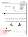
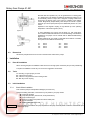
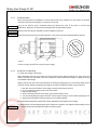
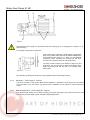
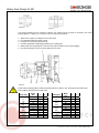
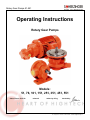
Rotary Gear Pumps 51-551
Operating Instructions
Rotary Gear Pumps
Models:
51, 76, 101, 151, 251, 351, 451, 551
date of issue: 04.07.00
Seite 1 / 1
release:2
written by: King
checked by:
Pumpenfabrik Ernst Scherzinger GmbH & Co. KG • Bregstr. 23-25 • 78120 Furtwangen/ Germany
Tel.: +49 (0) 77 23 – 65 06-0 • Fax: 65 06-40 • E-Mail: [email protected]
Rotary Gear Pumps 51-551
0.
Contents
0.
Contents ................................................................................................................................................................................. 2
1.
General ................................................................................................................................................................................... 3
1.1.
Usage ............................................................................................................................................................................. 3
1.2.
Pump Model Designation ................................................................................................................................................ 3
1.3.
Pump Data ...................................................................................................................................................................... 3
1.4.
Representatives .............................................................................................................................................................. 4
2.
Safety...................................................................................................................................................................................... 4
2.1.
Symbols Used In These Operating Instructions .............................................................................................................. 4
2.2.
Personnel Qualification ................................................................................................................................................... 5
2.3.
Possible Dangers If Safety Warnings Are Not Observed ................................................................................................ 5
2.4.
Local Safety Regulations ................................................................................................................................................ 5
2.5.
Safety Guidelines For The Operator ............................................................................................................................... 5
2.6.
Safety Guidelines For Maintenance, Assembly and Disassembly................................................................................... 5
2.7.
Technical Changes And Manufacturing Of Spare Parts.................................................................................................. 5
2.8.
Inadmissible Operation ................................................................................................................................................... 5
3.
Transportation And Storage .................................................................................................................................................... 6
3.1.
Shipping .......................................................................................................................................................................... 6
3.2.
Transportation................................................................................................................................................................. 6
3.3.
Storage ........................................................................................................................................................................... 6
3.4.
Preparation For Storage After Use.................................................................................................................................. 6
4.
The Pump ............................................................................................................................................................................... 6
4.1.
Principle Of A Gear Pump............................................................................................................................................... 6
4.2.
Design of the Lubrication Pumps .................................................................................................................................... 7
4.2.1.
General Design ....................................................................................................................................................... 7
4.2.2.
Directions of Flow.................................................................................................................................................... 9
4.2.3.
Internal Relief Valve ................................................................................................................................................ 9
4.2.4.
Shaft Seals And Bearings ....................................................................................................................................... 9
4.3.
Dimensions ................................................................................................................................................................... 10
5.
Installation............................................................................................................................................................................. 10
5.1.
Place Of Installation ...................................................................................................................................................... 10
5.2.
Tools ............................................................................................................................................................................. 10
5.3.
Initial Installation ........................................................................................................................................................... 10
5.3.1.
Check Before Installation ...................................................................................................................................... 10
5.3.2.
Pump With Motor .................................................................................................................................................. 11
5.3.3.
Pumps For Foot Mounting..................................................................................................................................... 11
5.3.4.
Mounting C - Face Pumps (F - Version)................................................................................................................ 12
5.3.5.
Motor Assembly Of C – Face Pumps (ZK - Version)............................................................................................. 12
5.3.6.
Electric Connection ............................................................................................................................................... 14
5.3.7.
Piping .................................................................................................................................................................... 14
6.
Start UP / Shut Down............................................................................................................................................................ 14
6.1.
Prepare For Operation .................................................................................................................................................. 14
6.2.
Start Up......................................................................................................................................................................... 15
6.3.
Relief Valve................................................................................................................................................................... 15
6.4.
Monitoring ..................................................................................................................................................................... 16
6.5.
Shut – Down ................................................................................................................................................................. 16
6.6.
Dismounting .................................................................................................................................................................. 16
7.
Maintenance ......................................................................................................................................................................... 17
7.1.
General Information ...................................................................................................................................................... 17
7.2.
Inspection...................................................................................................................................................................... 17
7.3.
Repair Work .................................................................................................................................................................. 17
7.4.
Tools ............................................................................................................................................................................. 17
Seite 2 / 2
Pumpenfabrik Ernst Scherzinger GmbH & Co. KG • Bregstr. 23-25 • 78120 Furtwangen/ Germany
Tel.: +49 (0) 77 23 – 65 06-0 • Fax: 65 06-40 • E-Mail: [email protected]
Rotary Gear Pumps 51-551
1.
General
This manual includes all necessary information required during installation, operation and maintenance. It Should
be read prior to commencing installation and operation. It is absolutely necessary to store the manual within reach
of the pump.
In additional to this manual, the operating instructions of the motor should be read and always be kept within reach
of the pump.
1.1.
Usage
Pumps described in these operating instructions are capable of pumping lubricating liquids. All liquids must be non
- corrosive for the used materials (see section 1.3).
Should you require any additional information regarding the pump, contact Scherzinger Pumpen GmbH & Co. KG,
Scherzinger Pump Technology Inc. or their local authorized distributor. Please state the pump model and the date
of manufacture in your correspondence.
1.2.
Pump Model Designation
This manual is valid for the lubrication pumps 51, 76 102, 151, 251, 351, 451 and 551 beginning with the year
1998, manufactured by Ernst Scherzinger GmbH & Co KG, 78120 Furtwangen, Germany.
The date of manufacture is stamped on the casing. The first letter marks the year of manufacturing, the following
number the month of manufacturing. To determine the year, we started in 1997 with the letter F was used (G:1998,
H:1999, I:2000, etc.).
The bottom line of this manual shows the issue and date of issue of this operating instruction.
All the described motor pumps in these operating instructions conform with valid EG - laws and are allowed to
carry the CE symbol.
1.3.
Pump Data
Max. Operating Pressure (outlet side)
Max. System Pressure (inlet side)
Max. Suction
Max. Pressure Rise
Flow Rate at 1400 RPM, 50mm²/s
and 2 Bar Pressure Rise
Storage Temperature
Operating Temperature
Viscosity Range
Speed Range
Seite 3 / 3
30 Bar (435 psi)
0,2 Bar (3 psi)
20 Bar (290 psi)
25 Bar (363 psi)
-0,4 Bar (-6 psi)
-0,8 Bar (-11,5 psi)
30 Bar (435 psi)
10 Bar (145 psi)
30 Bar (425 psi)
Size
51
Size
76
Size
101
Size
151
Size
251
Size
351
Size
451
Size
551
+10 to +50°C (50 to 122°F)
-20 to +80°C
(-8 to 176°F)
-10 to +160°C
(-8 to 320°F)
-20 to +100°C
(-8 to 212°F)
-20 to +60°C
(-8 to 140°F)
2 to 3000 mm2/s
100 to 1800 RPMn
(with Lip Seal Ring)
(with Magnetic Drive)
(with Packing)
(with Lip Seal Ring)
(with Magnetic Drive)
(with Lip Seal Ring)
(with Magnetic Drive)
(with Packing)
2,8 l/min (0,73 GPM)
3,7 l/min (0,96 GPM)
5,2 l/min (1,35 GPM)
7,6 l/min (1,97 GPM)
16 l/min (4,16 GPM)
26 l/min (6,75 GPM)
43 l/min (10,9 GPM)
69 l/min (17,9 GPM)
(Seals Buna N)
(Seals Viton)
(Seals PTFE)
(Seals EPDM)
Pumpenfabrik Ernst Scherzinger GmbH & Co. KG • Bregstr. 23-25 • 78120 Furtwangen/ Germany
Tel.: +49 (0) 77 23 – 65 06-0 • Fax: 65 06-40 • E-Mail: [email protected]
Rotary Gear Pumps 51-551
WARNING
1.4.
Noise
< 70 dB(A),
Ground Gears, speed 1400
RPMn Pressure Rise 20 Bar,
Operating Temperature 20°C,
Liquid 200 mm²/s, Lubricant
Dimensions
Materials in Contact With Liquid
see data sheets
Casing
Cover
Shafts
Gears
Seals
Liquids
Motors
See Quotation
C-Face or bare shaft pumps are delivered without electric motor.
For motor pumps see specification of drive manufacturer or
distributor
Cast Iron GG-25
Cast Iron GG-25
Case Hardened Steel
Case Hardened Steel
Buna N (standard)
PTFE (if requested)
Viton (if requested)
EPDM (if requested)
If you intend to operate the pump outside of the above given parameters, please consult the manufacturer of the
pump. Modifications may be necessary to ensure successful operation. Otherwise the pump or your system may
be damaged.
Representatives
Please contact Scherzinger Pump Technology Inc. for the representative in your area.
2.
Safety
Equipment that is incorrectly installed, operated in a dangerous manner, or poorly maintained, is a potential safety
hazard. If all reasonable precautions are not taken, the result may be personal injury or damage to equipment.
2.1.
Symbols Used In These Operating Instructions
These operating instructions contain safety regulations. If these regulations are ignored, the result may cause
injury or death. Warnings are noted with the following symbols:
danger symbol
high voltage symbol
symbol referred to DIN 4844 - W9
symbol referred to DIN 4844 – W8
Please pay close attention to items marked with the following symbol. Pump or system damage is possible if these
warnings are ignored.
WARNING
Information plates attached directly to the pump:
Sign with direction of rotation
Declaration of fluid connections
Date of manufacture
Name plate
This information must be observed and preserved.
Seite 4 / 4
Pumpenfabrik Ernst Scherzinger GmbH & Co. KG • Bregstr. 23-25 • 78120 Furtwangen/ Germany
Tel.: +49 (0) 77 23 – 65 06-0 • Fax: 65 06-40 • E-Mail: [email protected]
Rotary Gear Pumps 51-551
2.2.
Personnel Qualification
Individuals responsible for operation, maintenance and assembly of this equipment require proper training. It is
essential the operator is aware of proper operational methods. This operating manual must be read and
understood before installing and operating the pump.
2.3.
Possible Dangers If Safety Warnings Are Not Observed
Failure to observe safety warnings may cause danger to the personnel, environment and the pump. Liability claims
are also possible.
Examples of such dangers are:
Malfunction of the pump
Electrical shock
Mechanical failure
Danger to the environment by leakage
2.4.
Local Safety Regulations
The installation and operation of the pump must comply with national and local health, legislation, and safety
regulations.
2.5.
Safety Guidelines For The Operator
Protect hot or cold machine parts against touching.
Leaking dangerous liquids (e.g. explosive, poisonous, hot) must be drained, to ensure they do not cause
danger to personnel and the environment. Laws must be obeyed.
Electrical dangers must be avoided.
2.6.
Safety Guidelines For Maintenance, Assembly and Disassembly
Maintenance, assembly and disassembly must be performed by skilled technicians, who have read these
operating instructions.
Perform all work while the pump is not in operation.
If you are pumping noxious liquids, the pump must be decontaminated prior to performing maintenance.
After completion of maintenance, all safety devices must be reinstalled.
Prior to start up, all guidelines must be followed.
2.7.
Technical Changes And Manufacturing Of Spare Parts
It is necessary to consult the manufacturer prior to make modifications and technical changes to the pump. We
recommend the use of spare parts produced by the manufacturer. The use of other parts will void your warranty.
2.8.
Inadmissible Operation
The safe operation of the pump model is only possible if the pump is operated in a correct manner according to
section 1 - General – of this operating manual. The pump data in the data sheet must also be observed.
Seite 5 / 5
Pumpenfabrik Ernst Scherzinger GmbH & Co. KG • Bregstr. 23-25 • 78120 Furtwangen/ Germany
Tel.: +49 (0) 77 23 – 65 06-0 • Fax: 65 06-40 • E-Mail: [email protected]
Rotary Gear Pumps 51-551
3.
Transportation And Storage
3.1.
Shipping
The pumps are packaged to prevent corrosion (painted / if the pumps are not painted, they are oiled) and damage
during shipment. Additionally, the inlet and outlet ports are plugged to prevent leakage of retained test liquid,
protect the threads, and to prevent particles from reaching the internals of the pump.
3.2.
Transportation
To avoid shipping damage, protect the transportation box against impact.
We guarantee that the pump at time of delivery was working well. The pump was packaged in a suitable
transportation box. After receipt, inspect pump immediately for shipping damage. If you discover damage
immediately contact the forwarder agent and/or supplier.
3.3.
Storage
If the pump is stored and will be used later heed to following points:
Do not store the pump in wet or humid rooms
Do not put mechanical load on the shaft end
Let inlet and outlet ports plugged
Storage temperature to section 1.3.
If pumps should be stored than 6 months, metallic parts must be specially protected against corrosion.
3.4.
Preparation For Storage After Use
For shut-down and dismount see sections 6 and section 7.
Depending on the liquid pumped, there are different methods for preparing the pump for storage. If liquids without
poisonous or aggressive additives were pumped, flush the pump for one minute with at operating speed with new
lubricating oil.
If toxic or aggressive liquids were pumped, be sure to follow all safety precautions. First, flush the pump with a
neutralizing liquid at operating speed. Parts such as the relief valve (section 6.3), magnetic coupling (section 4.2.4)
and packing box (section 4.2.4), which cannot be cleaned completely by flushing the pump need to be
disassembled and cleaned by hand.
WARNING
If liquids that solidify have been pumped (e.g. paint), completely disassemble the pump (section 7.3). Clean all
parts by hand to guarantee a successful start up. Clean the pump with normal detergent (see resistance of pump
materials). After assembly the pump should be flushed with a preserving oil at operating speed.
When handling noxious liquids, adhere to all safety regulations!
4.
The Pump
4.1.
Principle Of A Gear Pump
Gear pumps are rotary displacement pumps in which two gears engage with each other. The transfer of fluid is
caused by counter rotation of two gears in a gear chamber. The gears are fixed on two shafts, which are running in
bearings in the casing and the cover. The shaft drives one gear. The other is driven by the first gear. The opening
teeth create a suction, which draws the liquid into the pump (figure 4.1). The liquid is transported between the teeth
and the gear chamber to the pressure side (figure 4.2, figure 4.3). When the gear teeth mesh, the liquid is
squeezed out and pressed into the discharge port (figure 4.4). In this way liquid can be pumped against pressure.
Seite 6 / 6
Pumpenfabrik Ernst Scherzinger GmbH & Co. KG • Bregstr. 23-25 • 78120 Furtwangen/ Germany
Tel.: +49 (0) 77 23 – 65 06-0 • Fax: 65 06-40 • E-Mail: [email protected]
Rotary Gear Pumps 51-551
→
→
→
4.2.
→
→
→
→
→
→
→
→
→
→
figure 4.1
figure 4.2
figure 4.3
figure 4.4
Design of the Lubrication Pumps
4.2.1.
General Design
The robust body consists of two parts: Casing 1 and cover 2. The pump design lends itself to easy, fast and
economic maintenance. The cover is screwed with either four or six screws to the casing. The two parts are sealed
an O - ring 3. The gears and the shafts are pressed together and run in sleeve bearings – the casing and the
cover itself are the bearings. The torque is transmitted from the drive shaft with drive gear 4 to the idler shaft with
idler gear 5. The standard shaft is a lip seal ring 6.
Scherzinger lubrication pumps are available in eight different pump sizes (size 50 to size 550, flow rates see Pump
Data, section 1.3) and four different mounting variations (
figure 4.5 to figure 4.8).
The shown cut away drawings are valid for the pump sizes 151 and 251 and may vary in details for the other sizes.
2
3
1
4
5
Å
6
figure 4.5 – foot mounted pump with lip seal ring – e.g. to screw to a base plate
Seite 7 / 7
Pumpenfabrik Ernst Scherzinger GmbH & Co. KG • Bregstr. 23-25 • 78120 Furtwangen/ Germany
Tel.: +49 (0) 77 23 – 65 06-0 • Fax: 65 06-40 • E-Mail: [email protected]
Rotary Gear Pumps 51-551
2
3
5
1
6
4
7
figure 4.6 – C-face pump with lip seal ring – to mount e.g. directly to a gear box
2
3
5
1
6
4
7
8
figure 4.7 – C-face pump with lip seal ring to mount directly to a DIN – motor
2
3
2
4
9
5
6
7
8
figure 4.8 – Pump with lip seal ring mounted to an electric motor
Seite 8 / 8
Pumpenfabrik Ernst Scherzinger GmbH & Co. KG • Bregstr. 23-25 • 78120 Furtwangen/ Germany
Tel.: +49 (0) 77 23 – 65 06-0 • Fax: 65 06-40 • E-Mail: [email protected]
Rotary Gear Pumps 51-551
4.2.2.
Directions of Flow
Additional to the basic models of the pumps described in section 4.2.1, each pump is available with different
directions of flow.
If you look at the shaft end:
Clockwise Rotation - Inlet Port to the Left
Counter Clockwise Rotation - Inlet Port to the Right
If direction of rotation changes and inlet port to the left
If direction of rotation changes and inlet port to the right
4.2.3.
þ discharge port to the right
þ discharge port to the left
þ discharge port to the right
þ discharge port to the left
Internal Relief Valve
The optional available internal relief valve protects your system
against inadmissible high pressures. Depending on the needed
cracking pressure, it can be set with different springs to
pressures between 0 to 30 Bar (figure 4.9).
While cracking, the valve relieves internally from pressure to
suction side to protect the system and pump from damage.
Refer to section 6.3 for Relief Valve adjustment.
figure 4.9
4.2.4.
Shaft Seals And Bearings
The drive shaft can be sealed in different ways. In standard design the
shaft is sealed by a lip seal ring (figure 4.10). This kind of sealing mostly
is used for pumps with a low inlet pressure (-0,4 to 0,2 bar) and low
viscous liquids (up to 700mm²/s).
figure 4.10
If suction height reaches more than 4m up to 7m (-0,7 bar), often two Lip
Seals are used. If the liquids to be pumped have poor lubrication qualities
or is a highly viscous liquid, two lip seal rings are recommended. In this
case the space between the two lip seals are filled with grease (figure
4.11).
figure 4.11
figure 4.12
Seite 9 / 9
A Packing Box (figure 4.12) should be selected when the pump has to
handle inlet pressure (up to 25 bar) or the liquids to be pumped are highly
viscous (more than 1000mm²/s). If using high viscous liquids, reduced
pump speeds are recommended.
Advantages of Packing: It is easy to maintain. If it wears out and starts
leaking, it easily can be tightened.
Pumpenfabrik Ernst Scherzinger GmbH & Co. KG • Bregstr. 23-25 • 78120 Furtwangen/ Germany
Tel.: +49 (0) 77 23 – 65 06-0 • Fax: 65 06-40 • E-Mail: [email protected]
Rotary Gear Pumps 51-551
Absolute leak free operation only can be guaranteed if no rotating parts
(e.g. shafts) have to be sealed. The Magnetic Coupled Pump (figure 4.13)
is hermetically sealed. Pumps with a magnetic coupling transmit the
torque from the driving motor to the pump by magnetic forces without
contact. Magnetically coupled Rotary Gear Pumps can handle a system
pressure up to 20 bar (inlet pressure) and a differential pressure of -0,8 to
10 bar.
Operation of the magnetic coupling is only allowed up to the operating
temperature of the used magnets (150°C).
figure 4.13
In some applications, the pumps must be driven e.g. with a belt drive.
This creates an additional radial force to the shaft bearings. For Belt Drive
applications, the pumps can be ordered with an additional Ball Bearing
(figure 4.14).
Allowed radial forces at a speed of 1450 RPM and a lifetime of 10.000h,
force points to the middle of the feather key:
figure 4.14
4.3.
51:
76:
101:
151:
250 N
250 N
400 N
400 N
251:
351:
451:
551:
400 N
450 N
450 N
500 N
Dimensions
All relevant pump dimensions can be seen in the dimension sheets of the pumps.
5.
Installation
5.1.
Place Of Installation
When choosing the place of installation make sure there is enough space around the pump for easy maintaining.
The place of installation must be dry. Do not mount in aggressive environment.
5.2.
Tools
For mounting our gear pumps you need:
A wrench for the piping
A wrench or ring wrench for the mounting screws
Allan key for the coupling
5.3.
Initial Installation
5.3.1.
Check Before Installation
First check the pump for transportation damages (se section 3.2).
Verify the following information, some items may not pertain to your pump model:
Liquid to be pumped
Pump data (flow rate, pressure rise, motor performance)
Pump model and type
Direction of rotation and position of inlet and outlet ports
Type of Shaft Seal
Additional Ball Bearing for shaft
WARNING
Seite 10 / 10
If there are differences between the pump required and the pump received please contact the manufacturer prior
to starting the pump.
Pumpenfabrik Ernst Scherzinger GmbH & Co. KG • Bregstr. 23-25 • 78120 Furtwangen/ Germany
Tel.: +49 (0) 77 23 – 65 06-0 • Fax: 65 06-40 • E-Mail: [email protected]
Rotary Gear Pumps 51-551
5.3.2.
Pump With Motor
When choosing a place for installation, be sure the motor-pump unit is mounted on an even surface. If necessary,
use spacers near the mounting bolts 1 to ensure the unit is level.
WARNING
If you do not level the pump, mechanical stress may damage the motor or the pump or at least cause
malfunctions. Tighten the mounting screws carefully 2 after having leveled the pump.
WARNING
Make sure the unit is proper ventilated to avoid overheating of the motor.
WARNING
Avoid mounting the pump with the pump head down. In this case the lip seal is bad lubricated and may fail.
1
2
figure 5.1
The four mounting screws 2 are not in the scope of supply.
5.3.3.
Pumps For Foot Mounting
a) Pump with coupling on base plate
While assembling pump and motor make sure pump shaft and motor shaft are aligned well. There must be no
radial or axial forces on both shafts. This can be avoided by using a flexible shaft coupling. Couplings of this type
are available at Scherzinger.
Aligning of pump and motor has to be done before connecting the piping (figure 5.2). The mounting bases of pump
and motor must be parallel. For adjusting the height of the shaft, see dimension sheets of pump and motor.
1.
2.
3.
4.
5.
6.
Bolt down the motor (usually the more weighty component) with all four screws 1.
Fix the coupling parts with the stud screws to the shafts.
Align the pump roughly.
Screw in the fixing screws 2 for the pump. Pump must be easily to move.
Turn drive shaft slowly (through fan shroud 3 or by turning the coupling on motor shaft 4) pump aligns now.
Tighten screws 2. Make sure the pump does not move while doing this.
The axial clearance between the shaft ends must be determined by the supplier of the coupling.
WARNING
Seite 11 / 11
To guarantee both units are aligned properly some experience is required. Is the alignment is done badly, the force
on the shaft ends and the wear will be increased. The pump may fail.
Pumpenfabrik Ernst Scherzinger GmbH & Co. KG • Bregstr. 23-25 • 78120 Furtwangen/ Germany
Tel.: +49 (0) 77 23 – 65 06-0 • Fax: 65 06-40 • E-Mail: [email protected]
Rotary Gear Pumps 51-551
5
4
2
3
1
figure 5.2
After assembly of the coupling, it is requested to protect the coupling e.g. by a coupling guard - see figure 5.2 - 5 against touching.
b) Mounting a pump driven by a belt drive
Driving pumps with a V-Belt Drive, Flat Belt Drive or multiple belt
drive is only possible with pumps with an additional Ball Bearing
for the shaft end (see section 4.2.4 - figure 4.14 and additional
explanation). When calculating and choosing the belt drive,
check the max. shaft end load of the used pump model.
The pulley must be centered on the feather key (figure 5.3) and
fixed safely. The more the pulley is shifted to the shaft end, the
higher the bearing load and the less is the possible radial
bearing load.
figure 5.3
After assembly, protecting the belt drive by a guard against touching is absolutely necessary.
5.3.4.
Mounting C - Face Pumps (F - Version)
The way of mounting of c-face pumps differs with the application. A description how this pump has to be installed
cannot be made. If you need help in your special case of installation, do not hesitate to contact Scherzinger
Pumps.
5.3.5.
Motor Assembly Of C – Face Pumps (ZK - Version)
The delivered shaft coupling can be either consisting of two parts (see figure 5.4) that will be fixed to the shaft
ends or three parts (see figure 5.5) with a flexible compensating element.
Seite 12 / 12
Pumpenfabrik Ernst Scherzinger GmbH & Co. KG • Bregstr. 23-25 • 78120 Furtwangen/ Germany
Tel.: +49 (0) 77 23 – 65 06-0 • Fax: 65 06-40 • E-Mail: [email protected]
Rotary Gear Pumps 51-551
figure 5.4
figure 5.5
The coupling including the set screws are included. The coupling part of the pump is mounted in the correct
position (figure 5.6 - length a). To mount the motor to the pump do as follows:
1.
2.
3.
4.
5.
6.
Attach motor coupling 1 in distance b to the drive shaft.
Fix coupling part with set screw 2 to shaft.
Put motor 3 on fan shroud (shaft side up).
If needed, put flexible compensating element to the coupling part.
Attach pump with c-face flange 4 to the motor 3 (It may be helpful to turn the pump slightly).
Fix pump with Screws 5 (not in scope of delivery) to the motor.
1
4
6
2
5
3
figure 5.6
Please use the following table to determine the dimensions of a and b in mm. All measures are valid for ISO
motors, IMB 34 (tolerances due to ISO 7168):
Pump Size
51
51
51
76
76
101
101
101
451
451
451
*) upon request
Seite 13 / 13
Motor
Size
63
71
0,25
63
71
63
71
80
80
90
100
a
b
Pump Size
*)
*)
*)
*)
*)
*)
6
5,5
2
3
*)
*)
*)
*)
*)
*)
*)
-4
-3,5
0
3
*)
151
151
251
251
251
351
351
351
551
551
551
Motor
Size
71
80
71
80
90
80
90
100
90
100
112
a
b
6
5,5
1
5
2
2
2
*)
*)
*)
*)
-4
-3,5
0
3
-2
3
3
*)
*)
*)
*)
Pumpenfabrik Ernst Scherzinger GmbH & Co. KG • Bregstr. 23-25 • 78120 Furtwangen/ Germany
Tel.: +49 (0) 77 23 – 65 06-0 • Fax: 65 06-40 • E-Mail: [email protected]
Rotary Gear Pumps 51-551
5.3.6.
Electric Connection
Motor connections should be done in accordance with local laws and legislation. Also pay attention to the
operating instructions of the motor.
To receive the maximum motor torque, always use a delta connection.
5.3.7.
Piping
It is very important to install correct fittings to the pump. All fittings should screw together easily, use force only for
final seat.
WARNING
Avoid pipe connections that place any external strains or loads on the pump.
The piping must have a suitable inner diameter. The minimum diameter is the nominal widthof the pump
connections. On the suction side of the pump, we recommend piping one size larger than the nominal width of the
pressure side. As directional quantity we recommend following maximum flow velocities in the piping.
Suction Piping
Discharge Piping
WARNING
Up to 200 mm²/s
1,5m/s
3,0m/s
Up to 600 mm²/s
1,0m/s
2,0m/s
Up to 2000 mm²/s
0,5m/s
1,0m/s
To protect the pump from damage caused by solids in the liquid, we recommend a 50-micron filter in the suction
piping. Be sure the filter does not cause a serious pressure drop.
Suction piping should be as straight and direct as possible to the pump with a minimum number of elbows. We
recommend using long radius elbow type.
The suction pipe should have a continuous rise to the pump. If it is necessary to install the piping rising and
descending, there must be a provision to purge air at the highest points of the piping.
WARNING
After installing the piping, be sure it is free of sediments and chips. Otherwise the pump may be damaged.
If the suction head will be greater than 4 meters, we recommend installing a check valve in the suction piping.
Please contact the manufacturer for suction strainers with an integrated check valve in various sizes.
Gear pumps must not operate against closed valves or a system closed to its discharge side. The pump can
create a hazardous pressure rise, which can system environmental damage. We recommend a pump with an
integrated relief valve, or a relief valve installed directly in the discharge pipe of the pump.
In situations where de-aerating is a critical process, the installation of isolating valves, located directly before the
inlet port and directly after discharge port is recommended. This allows for removal of the pump without draining
the complete system.
Pipes should be screwed together and not leak, otherwise air may penetrate into the pump, which will prevent the
pump from sucking, or on the discharge side the liquid could drop out.
It may be necessary to integrate silencers in the piping.
6.
Start Up / Shut Down
6.1.
Prepare For Operation
After complete installation, before start up check the pump and the environment by following questions:
Is it possible to turn the pump by hand (small pumps) or with a tool (big pump)?
Are suction and pressure piping connected correctly?
Do pump and drive have the same direction of rotation?
Is the time of dry running restricted to a minimum?
Are the pump internals wetted with the liquid to be pumped if the pump has to prime (max. dry running time 20
sec.)?
are check valves, valves in right position?
Seite 14 / 14
Pumpenfabrik Ernst Scherzinger GmbH & Co. KG • Bregstr. 23-25 • 78120 Furtwangen/ Germany
Tel.: +49 (0) 77 23 – 65 06-0 • Fax: 65 06-40 • E-Mail: [email protected]
Rotary Gear Pumps 51-551
Are the pipes checked for leakage?
Is it possible to stop the pump by an emergency switch in case of malfunction?
Is enough liquid in the reservoir?
If temperature of pumps and liquid differ more than 50°C the pump has to be adapted in temperature!
Are all rotating parts protected against touching?
6.2.
Start Up
Flush the system and the pump head with the liquid to be pumped.
Adjust relief valve to wanted pressure according to section 6.3.
Dry running time should not extend 20 seconds.
WARNING
6.3.
Relief Valve
With the integrated relief valve it is possible to determine the relative pressure rise to exact value (see section
4.2.3).
All relief valves are tested to ensure they are in good working condition. Relief valves are not set at a specific
value, unless requested by the customer.
The relief valve should be set while the pump is operating. Measure the pressure on the outlet side of the pump.
Pay attention to do the adjustment with the correct operating conditions:
Flow Rate
Temperature
System Pressure
Speed of Rotation
Correct Valve Spring
Two different valve types are available: (figure 6.1 and figure 6.2)
1
2
3
4
5
6
7
8
9
figure 6.1 – relief valves of pump types 101, 151 and 251
Adjusting Valves of the Types 101, 151 and 251
1. Unscrew plug screw 1 and remove seal 2
2. Adjust the relief valve by turning the adjusting screw 2 with an Allan key
• To the left (counter clockwise)
=> decreasing the crack pressure
• To the right (clockwise)
=> increasing the crack pressure
• Scherzinger recommends to set the crack pressure about 20% higher than the needed pressure rise
3. Replace plug screw 1 and seal 2 and tighten both
Seite 15 / 15
Pumpenfabrik Ernst Scherzinger GmbH & Co. KG • Bregstr. 23-25 • 78120 Furtwangen/ Germany
Tel.: +49 (0) 77 23 – 65 06-0 • Fax: 65 06-40 • E-Mail: [email protected]
Rotary Gear Pumps 51-551
1
2
3
4
5
6
7
8
9
figure 6.2 - relief valves of pump types 51, 76, 351, 451 and 551
Adjusting Valves of the Types 51, 76, 351, 451 and 551
1. Unscrew and remove cap screw 1 and open counter nut 5
2. Adjust the relief valve by turning the adjusting screw 2 with a screw driver
• To the left (counter clockwise)
=> decreasing the crack pressure
• To the right (clockwise)
=> increasing the crack pressure
• Scherzinger recommends to set the crack pressure about 20% higher than the needed pressure rise
3. Tighten counter nut 5 to fix the adjusting screw
4. Replace and tighten cap screw 1
5. Make sure all seals 4 are rearranged correctly
While cap screw (plug screw) 1 is opened, a small amount of leakage is possible.
WARNING
The relief valve is designed for a short-term overload protection. Pumping liquid through a relief valve will generate
heat in the liquid. For application at ambient operating temperatures, if the relief valve is opened more than 3
minutes, damage to the pump head could occur. The higher the operating temperature, the shorter the possible
relief valve opening time.
WARNING: do not remove adjusting screw while pump is in operation or the system is under pressure. Liquid can
spurt out and cause personal injuries!!
6.4.
Monitoring
WARNING
6.5.
We recommend installing a manometer on the outlet side of the pump to check the operating pressure. If the
operating temperature is greater than 80°C we recommend installing a temperature gauge. Temperatures greater
than 80°C (Buna N) or 160°C (Viton) may destroy the seals or damage the magnets (with magnetic coupling).
Shut – Down
Reduce the speed of rotation, if possible, to half operating speed.
Drain the pump head by reducing the outlet pressure to atmospheric pressure and remove the suction piping
out of the liquid tank so that the pump sucks air (not if the system is under pressure).
Be sure the pump does not run dry for more than 30 seconds.
If you are pumping noxious liquids, flush the pump with a neutralizing liquid.
Flush the pump with lubrication oil (e.g. Shell GF68).
6.6.
Dismounting
Switch off drive motor and remove electric connections. Make sure all steps in section 6.5 have been
completed.
Remove the pump
Seite 16 / 16
Pumpenfabrik Ernst Scherzinger GmbH & Co. KG • Bregstr. 23-25 • 78120 Furtwangen/ Germany
Tel.: +49 (0) 77 23 – 65 06-0 • Fax: 65 06-40 • E-Mail: [email protected]
Rotary Gear Pumps 51-551
7.
Maintenance
7.1.
General Information
Be sure that the pump head is cleaned with a non-toxic liquid. In the event the pump head was operating with
dangerous or noxious liquids, use necessary safety precautions.
7.2.
Inspection
All internal bushings are sleeve bearings, lubricated by the pumped liquid. Only one pump version (see section
4.2.4 - figure 4.14) is equipped with an additional ball bearing at the shaft end. Also for this type no maintenance is
necessary.
7.3.
Repair Work
WARNING
7.4.
If the pump head has been disassembled, it is necessary to replace all O–rings to ensure a proper seal.
An exact description of the maintenance steps can, due to the various pump types, not be supplied.
Please consult the matching spare part list.
Tools
For maintenance you will need:
Allan key 2 to 10mm
Wrench 8 to 40 mm
Dynamometric key (3 to 40 Nm)
pliers for retaining rings for shafts and bores (DIN471 / 472)
pincers to remove the feather keys
tool to press in the lip seal rings
Seite 17 / 17
Pumpenfabrik Ernst Scherzinger GmbH & Co. KG • Bregstr. 23-25 • 78120 Furtwangen/ Germany
Tel.: +49 (0) 77 23 – 65 06-0 • Fax: 65 06-40 • E-Mail: [email protected]
Rotary Gear Pumps 51-551
Ernst Scherzinger GmbH & Co. KG
Bregstrasse 23
78120 Furtwangen
PO Box 11 54
78113 Furtwangen
Telephone
Telefax
+49 / 0 77 23 / 65 06 –0
+49 / 0 77 23 / 65 06 – 40
Internet:
E-Mail:
http://www.scherzinger.de
[email protected]
Seite 18 / 18
Pumpenfabrik Ernst Scherzinger GmbH & Co. KG • Bregstr. 23-25 • 78120 Furtwangen/ Germany
Tel.: +49 (0) 77 23 – 65 06-0 • Fax: 65 06-40 • E-Mail: [email protected]