1
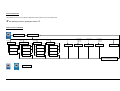
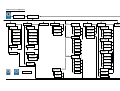
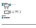
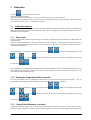
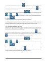
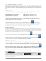
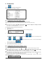
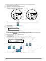
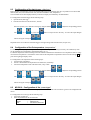
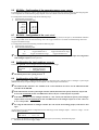
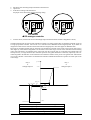
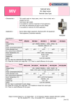
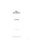
Edition 03/12
Draft
Operating Instructions
Manual
Intelligent Controller
for pH, redox (ORP), ISE, conductivity, oxygen, chlorine
MV 5010
MV 5020
MV 5025
MV 5030
MV 5060
MV 5010-F
MV 5020-F
MV 5025-F
MV 5030-F
MV 5060-F
MV 5010 CAN
MV 5020 CAN
MV 5025 CAN
MV 5030 CAN
MV 5060 CAN
Sensortechnik Meinsberg GmbH
Quality System certified to DIN EN ISO
Kurt-Schwabe-Straße 6
D-04720 Ziegra-Knobelsdorf/Germany
Internet: www.meinsberg.de
Tel.:
+49 34327 623-0
Fax:
+49 34327 623-79
1.
OVERVIEW ............................................................................................................................3
2.
SAFETY..................................................................................................................................3
3.
CONNECTION DIAGRAM, MEASURAND ........................................................................5
4.
SENSOR CONNECTION DIAGRAMS................................................................................7
4.1 Temperature Sensor.......................................................................................................................... 7
4.2 pH/redox (ORP) and Ion-Selective (ISE) Electrode ................................................................... 8
4.3 Conductivity Measuring Cell, Oxygen and Chlorine Sensor.................................................... 9
4.4 Cable Length Influence...................................................................................................................10
5.
BUTTON, DISPLAY, MENU STRUCTURE, PASSWORD PROTECTION...................11
6.
MV 50XX CAN .....................................................................................................................15
7.
CALIBRATION ....................................................................................................................17
7.1 Calibration methods ........................................................................................................................17
7.1.1 Data „input“....................................................................................................................................17
7.1.2 Setting the Temperature Offset „temp.offs. ................................................................................17
7.1.3 Single-Point Calibration „one point“...........................................................................................17
7.1.4 Two-Point Calibration „two point“..............................................................................................18
7.1.5 Automatic Calibration „automatic“ .............................................................................................19
7.2 Calibration error..............................................................................................................................19
8.
CONFIGURATION ..............................................................................................................20
8.1 Configuration of the relay outputs „limits“................................................................................20
8.2 Configuration of the current / voltage „outputs“ ......................................................................20
8.3 Configuration of the data logger „data logg.“............................................................................22
8.4 Configuration of the fix temperature „temperature“...............................................................22
8.5 MV 5010 – Configuration of the „sensortype“...........................................................................22
8.6 MV 502x – Configuration of the measuring range „meas. range“ ........................................23
8.7 MV 5030 – Configuration of the „main value“..........................................................................23
8.8 Configuration the basic settings „general“ ................................................................................23
8.9 Configuration of the PID „controller“.........................................................................................23
8.9.1 Configuration of a pulse length controller (PWM) ....................................................................25
8.9.2 Configuration of an analogue controller......................................................................................26
9.
DATA LOGGER ..................................................................................................................27
9.1 Interface MV 5000 USB..................................................................................................................27
10. CALIBRATION INFORMATION ........................................................................................29
11. MAINTENANCE, DISPOSAL.............................................................................................29
11.1 Sensor / Electrode Maintenance....................................................................................................29
11.2 Disposal...............................................................................................................................................29
12. SPECIFICATIONS...............................................................................................................29
13. ACCESSORY PARTS ........................................................................................................31
2/31
1. Overview
The intelligent controllers are excellent components for continuous measurement and controlling of several analytical parameters. They are separated self sufficient devices, which transform, display, save and provide for further processing the
signals of the connected electrochemical sensors. The series of the MV50xx and of the MV50xxCAN in an IP65 aluminium
case and the series MV50xx-F in a plastic case for front panel mounting have a big OLED-display and an intuitive pain text
menu structure. This warranted a comfortable handling. All data will be stored in the integrated data logger. Each controller
features measurement of the corresponding parameter and the temperature, if a sensor with integrated temperature probe or a
separated temperature sensor is used, two isolated outputs for current 0(4)…20 mA or voltage 0…5 V DC, two floating limit
or alarm relay output as well as a RS232/USB interface almost for documentation and configuration purposes.
pH, redox potential (ORP) and ISE (ion selective electrodes) controllers are suitable for direct connection with combination
electrodes and separated measuring chains. Conductivity cells and membrane covered amperometric oxygen sensors for
connection with the accompanying conductivity and oxygen controller should be equipped with an integrated temperature
sensor. The controllers accept temperature sensors Pt 1000. The chlorine controller is suitable for direct connection with
sensors for measurement of disinfectants (free and total chlorine, chlorine dioxide, ozone) if these sensors feature a 2-wire
analogue current output.
2. Safety
This Operating Instructions Manual contains fundamental information that should be observed in connection with the installation, start-up, operation and maintenance of the MV50xx Measuring System. Therefore, it is absolutely vital for the user to
read this Manual prior to working with it.
User qualification
The single-parameter controller and the entire measuring system have been designed for analytical-parameter measurements.
It is assumed that the user/operator and the maintenance personnel have the proper professionals skills and experience to
know the specific properties of analytical measuring systems, master the safe handling of chemicals, for example, in the
maintenance of electrodes/sensors, and can assess any dangers and risks resulting thereof. The user must ensure that the national legislation and procedures concerning the protection of labour, the prevention of accidents and the handling of chemicals are observed.
Electrical installation work
The single-parameter controller comes ready for operation together with a power supply cable. Do not insert the plug into
sockets other than shock-proof. Do not use an extension cable without any protective conductor, as this would eliminate the
protective function. Any interruption of the protective conductor inside or outside the unit may result in the latter becoming
dangerous if another fault occurs.
Opening the unit will expose live parts. The terminal box may only be opened for the connection of sensors and other peripheral units after the mains supply has been unplugged. Such work should be done by a skilled person who is familiar with the
hazards associated therewith. Intervention into the unit will result in expiration of the warranty.
Installation and getting started
Install the device so that the conditions specified under 'Specifications' will be kept under any circumstances. The enclosures
meet the IP 65 degree of protection requirements (MV5000-F only in connection with installed transparent front cover!). A
prerequisite to this, however, is the proper installation of the enclosure cover of the terminal box and of the seals (Important:
Distinguish between the inside and outside.). Also, properly install the cables in the glands and tightly seal all cable glands not
used. For outdoor application of the MV50xx controller the use of a stand and a weather-proof roof is recommended. Do not
use any sensor and bus cables other than recommended by the manufacturer. For the sensors and accessories, the instructions
and regulations in the respective operating instructions manuals and specification sheets shall apply.
Proper usage
The controllers are intended for measuring, controlling and regulating analysis parameters. Taking into consideration the
'Specifications' paragraph in Chapter 12 operating and using the unit for this application is the proper usage. Any application
beyond this and individual modifications or extensions are improper and will lead to loss of entitlement to the warranty.
When connecting the unit with electrochemical sensors, always take into account their life and natural wear as this may result
in malfunctioning of the measuring system and the regulation or control associated therewith. The user must take suitable
measures to limit harmful effects of such malfunctioning.
General safety instructions
The controllers have been manufactured and tested in accordance with the relevant guidelines and standards for electronic
measuring equipment. They have left the factory in technically unobjectionable condition.
The proper functioning and the operational reliability of the controllers will only be guaranteed if the generally usual safety
precautions and the specific safety instructions given in this operating instructions manual and in the operating instructions
manuals of the components are observed. If it is assumed that safe operation of the unit or of its components is no longer
3/31
possible, remove the unit and its components from service and protect it against unintentional operation. Safe operation will
no longer be possible if the unit or its components
• show any transport damage.
• has/have been stored under unsuitable conditions for a longer time.
• show any apparent damages.
• does/do no longer work as described in this Operating Instructions Manual.
If in doubt, please contact your supplier.
4/31
3. Connection Diagram, Measurand
X3.1
X3.2
X3.3
sensor
Pt 1000-1
Pt 1000-1
Pt 1000-2
Pt 1000-2
X4.1
X4.2
X4.3
X4.4
X4.5
X4.6
X4.7
X4.8
X4.9
X4.10
X4.11
HOLD
GND
O1 (0/4…20mA) (0…5 V)
O2 (0/4…20mA) (0…5 V)
Terminals Connection
MV50xx
MV 50xx CAN
GND
CAN H
CAN L
only in MV 50xx CAN
Terminal pH / redox(ORP) / ISE*
relays 1
X2.1
)X2.2
X2.3
X2.4
X2.5
X2.6
relays 2
(+) L
power
PE
110…240 V AC
(15..30 V DC) (-) N
X1.1
X1.2
X1.3
RS232/USB
CAN Bus
X5.1
X5.2
X5.3
conductivity
2-electrode-cell
screen
signal wire
screen
conductivity
4-electrode-cell
measuring electrode
supplying electrode
supplying electrode
measuring electrode
oxygen
chlorine
anode
cathode
anode
sensor sensor +
sensor -
X4.11
X4.10
X4.9
X4.8
guard
measuring electrode
guard
screen/reference electrode
X4.7
X4.6
X4.5
X4.4
temp. sensor Pt 1000-1
temp. sensor Pt 1000-1
temp. sensor Pt 1000-2
temp. sensor Pt 1000-2
Pt 1000-1
Pt 1000-1
Pt 1000-2
Pt 1000-2
Pt 1000-1
Pt 1000-1
Pt 1000-2
Pt 1000-2
Pt 1000-1
Pt 1000-1
Pt 1000-2
Pt 1000-2
Pt 1000-1
Pt 1000-1
Pt 1000-2
Pt 1000-2
X4.3
X4.2
X4.1
free
HOLD
HOLD
free
HOLD
HOLD
free
HOLD
HOLD
free
HOLD
HOLD
free
HOLD
HOLD
* ISE: ion concentration measurement with an ion-selective electrode
Terminal
X3.3
X3.2
X3.1
Description
output 2: 0/4…20mA or 0…5 V refer to GND
output 1: 0/4…20mA or 0…5 V refer to GND
GND
5/31
X2.6
X2.5
X2.4
X2.3
X2.2
X2.1
Relay 1 n. c. contact
Relay 1 changeover contact (max. 250 V AC / 5 A)
Relay 1 n. o. contact
Relay 2 n. c. contact
Relay 2 changeover contact (max. 250 V AC / 5 A)
Relay 2 n. o. contact
X1.3
X1.2
X1.1
Mains supply neutral conductor / GND (24V DC)
Mains supply PE-conductor
Mains supply L-conductor / + 24V DC
X2.6 X2.5 X2.4 X2.3 X2.2 X2.1 X4.2 X4.1
(15..30 V DC)
L (+)
110…240 V AC
PE
power
N (-)
HOLD
relays 2
relays 1
Only in MV50xxCAN:
Terminal Description
X5.1
GND
X2.2
CAN H
X5.3
CAN L
X1.3 X1.2 X1.1
MV50xx-F
6/31
X4.4 X 4 . 3 X3.3
X3.2
X3.1
O1 (0/4…20mA) (0…5 V)
GND
X4.5
O2 (0/4…20mA) (0…5 V)
X4.6
Pt 1000-1
X4.7
Pt 1000-1
X4.8
Pt 1000-2
sensor
X4.11 X4.10 X4.9
Pt 1000-2
RS232
Measurement categories
In addition to the main measurement category (i.e. pH, conductivity, etc.) each controller delivers several so-called secondary
measuring categories determined or calculated from the main measurement category and the temperature as measurement
category. The configuration menu makes possible to put the following measurement categories to the outputs of the relevant
controller.
main
measurement value
second
measurement value
temperature
pH value
electrode voltage in mV
temperature in °C
redox potential (ORP)
as absolute voltage in
mV
redox potential (ORP)
referred to the standard
hydrogen electrode
in mV
temperature in °C
ISE voltage in mV
ion concentration in
concentration units
temperature in °C
MV 5020
conductivity in mS/cm
or µS/cm
resistance in ohms
temperature in °C
MV 5025
conductivity in mS/cm
or µS/cm
salinity in g/kg
temperature in °C
oxygen saturation index
in %
oxygen concentration
in mg/l
temperature in °C
MV 5010
(pH)
MV 5010
(Redox)
MV 5010
(ISE)
MV 5030
MV 5060
or selective:
oxygen concentration
in mg/l
oxygen saturation index
in %
temperature in °C
concentration
in mg/l
sensor output current
in mA
temperature in °C
4. Sensor Connection Diagrams
Temperature Sensor
X4.4
X4.5
X4.6
X4.7
Four-wire circuit
measuring cable
K43-PT/...
X4.4
PT1000-1
X4.5
PT1000-1
X4.6
PT1000-2
X4.7
PT1000-2
cable core
cable core
shield
shield
Three-wire circuit
Two-wire circuit
X4.4
X4.5
X4.6
X4.7
Pt 1000
X4.4
X4.5
X4.6
X4.7
4.1
Pt 1000
Pt 1000
7/31
4.2
pH/redox (ORP) and Ion-Selective (ISE) Electrode
X4.8
X4.9
X4.10
X4.11
Combination electrode
measuring
cable K43/...
X4.8
reference
X4.9
guard
X4.10
pH-signal
X4.11
guard
shield
-
cable core
-
X4.8
X4.9
X4.10
X4.11
Separated measuring and reference electrode
pH-sensor
reference electrode
X4.8
reference
X4.9
guard
X4.10
pH-signal
X4.11
guard
shield
cable core
-
cable core
-
-
X4.4
X4.5
X4.6
X4.7
X4.8
X4.9
X4.10
X4.11
pH combination electrode with integrated temperature sensor
(K 19 multi wire measuring cable)
X4.4
X4.5
X4.6
X4.7
X4.8
X4.9
X4.10
X4.11
pH combination electrode with
integrated temperature sensor
(K 54 triaxial cable)
PE
X4.4
PT1000-1
X4.5
PT1000-1
X4.6
PT1000-2
X4.7
PT1000-2
X4.8
reference
X4.9
guard
X4.10
pH-signal
X4.11
guard
measuring
cable K54/...
bridge circuit
to X4.5
bridge circuit
to X4.4
bridge circuit
to X4.7
outer shield
(grey)
inner shield
(red)
-
cable core
(blue)
-
measuring
cable K19/...
green
brown
yellow
white
shield
-
cable core
-
8/31
4.3
Conductivity Measuring Cell, Oxygen and Chlorine Sensor
X4.8
X4.9
X4.10
X4.11
conductivity
2-electrode-cell
X4.4
PT1000-1
X4.5
PT1000-1
X4.6
PT1000-2
X4.7
PT1000-2
X4.8
-
X4.9
-
X4.10
measuring
electrode
X4.11
measuring
electrode
measuring
cable K43/...
-
-
-
-
-
-
cable core
shield
measuring
cable K18/...
grey
green
brown
pink
-
-
white
shield
measuring electrode
supplying electrode
supplying electrode
measuring electrode
X4.8
X4.9
X4.10
X4.11
conductivity
4-electrode-cell
measuring
cable K17/...
X4.4
PT1000-1
X4.5
PT1000-1
X4.6
PT1000-2
X4.7
PT1000-2
X4.8
measuring
electrode
X4.9
supplying
electrode
X4.10
supplying
electrode
X4.11
measuring
electrode
shield
white
yellow
blue
pink
brown
green
grey
9/31
X4.8
X4.9
X4.10
X4.11
Oxygen sensor
cathode
anode
measuring
cable K39/...
X4.4
PT1000-1
X4.5
PT1000-1
X4.6
PT1000-2
X4.7
PT1000-2
X4.8
-
X4.9
anode
X4.10
cathode
X4.11
anode
grey
brown
green
pink
-
-
white
shield
X4.8
X4.9
X4.10
X4.11
Sensor for disinfectants (chlorine,
chlorine dioxide, ozone)
+
-
An integrated or separated temperature sensor connected as per para. 4.1
4.4
Cable Length Influence
If no impedance converter is used, the wiring for potentiometric sensors should not exceed 10 m. For conductivity and amperometric sensors and measuring cells, limit the maximum wiring length to 20 m. For detailed information, please refer to
the specification sheets of the sensors and to the technical information thereto.
10/31
5. Button, Display, Menu structure, Password protection
Button
opens the menu:
Calibration
Configuration
24h-data recorder
Information
navigation in the menu
Cursor left
Cursor up
Cursor down
Cursor right
selection / ENTER
input / change values
Cursor left
position value +1
position value -1
Cursor right
confirm / save value
Display
The Display changes after 20 min automatically in the energy-save-modus / screen-saver-modus. By touching of
any button (key) the display will be switched on for the next 20 min.
hold active
fix temperature active
calibration value out of range
(out of limits)
main
measurement value
second
measurement value
temperature
status relay 1: active
actual value analog output 2
status relay 2: inactive
actual value analog output 1
11/31
Password-protection
The calibration menu (CAL) and the configuration menu (CONF) are password-protected.
The default password for opening these menus is 1.
Menu structure Calibration
pass word
MV5010
Calibration
MV502x
input
MV5030
input
MV5060
input
input
asymmetrie
cell const.
slope
slope
slope
temp.coef.
B < 20°C.
B < 20°C
back
cable offset
B > 20°C
B > 20°C
back
back
back
temp.offs.
only MV5020
MV5025
MV5030
MV5060
only MV5010
only MV5010
MV5020
MV5025
MV5030
one point
two point
automatic
back
CAL INFORMATION
+
=
back
12/31
Menu structure Configuration
pass word
Configuration
not in
MV 5010-CAN
data logg.
outputs
limits
output 1
relay 1
temperature
only in
MV5010
sensortype
general
fixed temp.
pH
device id
controller
back
outp. type
select value
outp. val.
temp.-value
mv/redox
pass word
PWM
limit
val. 0/4mA
back
ISE
clock
current 0..20
hysterese
val. 20mA
meas.range
back
current 4..20
Min / Max
type
back
back
relay 2
output 2
only in
MV5020
20 µS
200 µS
…
…
2000 µS
times
100 mS
only in
MV5025
current
derivative t.
20 µS
200 µS
2000 µS
main value
back
only in
MV5030
%
mg/l
cycle time
meas.range
back
=
2. value
temperature
voltage
+
Meas. value
20 mS
type u/i
back
cont.value
integral time
minimal time
back
20 mS
parameters
500 mS
release
back
13/31
Menu structure Data recorder
back to measurement
1 time
back
next
time
first value info
next value info
Menu structure Info
CAL INFORMATION
14/31
6. MV 50xx CAN
The version MV50xxCAN provides the possibility to integrate the controllers in a bus-network with the multiparameter system KM3000. In this case the KM3000 is the master. Each controller (slave) must get a separate free
ID-number. This slave ID-number is factory-pre-adjusted or can be changed in the KM3000 (see also manual
KM3000 / para. „Change the slave-number (ID)“). It is extremely important that this number is assigned on the bus
only once. Otherwise conflicts are possible and the correct function of the whole system cannot be guaranteed.
sensor
Pt 1000-1
Pt 1000-1
Pt 1000-2
Pt 1000-2
HOLD
GND
O1 (0/4…20mA) (0…5 V)
O2 (0/4…20mA) (0…5 V)
The layout of the bus system necessitates series connection of the slaves (external KM3000-modules or MV50xx), the bus
line (special CAN-bus-cable) being looped through the module.
CAN bus
X4.1
X4.2
X4.3
X4.4
X4.5
X4.6
X4.7
X4.8
X4.9
X4.10
X4.11
GND - X5.1
CAN H - X5.2
CAN L - X5.3
GND - X5.1
CAN H - X5.2
CAN L - X5.3
resistor 120 Ω in the last slave in the CAN-bus!
relays 1
CAN L - X5.3
CAN bus cable
15/31
120 Ω
GND - X5.1
CAN H - X5.2
CAN L - X5.3
CAN H - X5.2
relays 2
CAN bus
PE
X2.1
)X2.2
X2.3
X2.4
X2.5
X2.6
X1.1
X1.2
X1.3
RS232/USB
CAN bus
X5.1
X5.2
X5.3
CAN bus
PE
(+) L
power
PE
110…240 V AC
(15..30 V DC) (-) N
X3.1
X3.2
X3.3
PE
At powering on measuring system it is very important that all MV50xxCAN already started before or powering
on simultaneously with the KM3000. Never later! Only than an error-free CAN-bus-communication is guaranteed
Please note that the configuration of the controllers and the calibration of the measuring points can be done
directly at the MV50xxCAN as well as at the KM3000. See also manual KM3000!
The desired temperature compensation must be adjusted separately in the KM3000 and in the MV50xxCAN.
Booth adjustments can be different! In the KM3000 always the measured temperature is displayed (by enabled
temperature display)! In the MV50xxCAN always the temperature used for compensation (measured or fixed) is
displayed.
The PID-controller function is not available in the version MV50xxCAN. Please use the bidirectional PIDcontrollers in the KM3000.
16/31
7. Calibration
Open with
+ password the calibration menu.
Select the calibration method.
All possible calibration methods for the respective measuring point type will be displayed.
Open your desired calibration method by selecting the corresponding menu item. The individual calibration methods
are explained in the next para. (7.1 Calibration methods).
7.1
Calibration methods
Take account of temperature compensation for all calibration methods. This means, if measured values are compensated by
temperature measurement, the associated temperature sensor must also be dipped into the calibration medium to be able to
determine the exact temperature.
7.1.1 Data „input“
Data input stands for the input of the specific ratings of the sensor connected that have, for example, been determined at the
laboratory before.
Select the corresponding calibration value whose settings you wish to change by. An input dialogue will now enable you to
change the values within corresponding limits. If you exceed these you will get an error message to prompt you to enter a
value within the fixed limits.
Select the position you would like to change by using the buttons
(+1) or
the value press
(-1). Press the
+
or
. Adjust the corresponding position with
-button to accept and save the entry. To cancel the input dialogue without saving
.
By the conductivity controller MV5020 and MV5025 the cable offset calibration value is included. That allows the entry of a
value (offset) for the compensation of the cable resistance. For this purpose, enter the cable resistance in Ohms for the 20
mS/cm and 100 mS/cm measuring ranges.
7.1.2 Setting the Temperature Offset „temp.offs.
This menu item enables you to set a temperature value offset. For this purpose open the menu item “temp.offs.”. Now, an
input dialogue will be displayed which facilitates the setting. The offset can be positive or negative.
Select the position you would like to change by using the buttons
(+1) or
the value press
7.1.3
(-1). Press the
+
or
. Adjust the corresponding position with
-button to accept and save the entry. To cancel the input dialogue without saving
.
Single-Point Calibration „one point“
Calibrate the measuring signal at this one point using a defined calibration solution or a known set point value, e. g. determined by a separate method or by means of a laboratory/field instrument. At first, you will be prompted to dip the sensor into
17/31
the corresponding calibration medium. After this step press
to accept the dialogue. Now, the currently measured value
will be displayed. After the measured value has attained a stable state, accept the dialogue again by pressing
now be prompted to enter the set point value.
Select the position you would like to change by using the buttons
(+1) or
(-1). Press the
or
. You will
. Adjust the corresponding position with
-button to accept and save the entry. To cancel the input dialogue without saving
the value press
+
.
As a result, you will now be given the new calibration values that will be save in the device.
For calibration of Controller MV5060 (linear characteristic for measurement of free or total chlorine) in conjunction with
corresponding chlorine measuring sensors, a single-point calibration as comparison with a known set point value determined
by a means of a photometric laboratory method is recommended. Chlorine measuring sensors feature automatic temperature
compensation integrated in the sensor. The temperature value shown during calibration is not taken into account.
7.1.4 Two-Point Calibration „two point“
Calibrate the sensor at two separate points using two different defined calibration solutions or known set point values. The
calibration points are supposed to include the measuring range or the measured values to be expected, respectively. You can
choose any sequence of the calibration solutions or set point values.
At first, you will be prompted to dip the sensor into the first calibration medium. After this step press
to accept the
dialogue. Now, the currently measured value will be displayed. After the measured value has attained a stable state, press
to accept the dialogue. You will now be prompted to enter the associated set point value.
Select the position you would like to change by using the buttons
(+1) or
(-1). Press the
or
. Adjust the corresponding position with
-button to accept and save the entry. To cancel the input dialogue without saving
the value press
+
.
The next dialogue field will now prompt you to dip the sensor into the second calibration medium. After you have accepted
this, the currently measured value will, again, be displayed. Press
again to accept the stabilised measured value, before
you will be prompted to enter the associated set point value.
As a result, you will now be given the new calibration values that will be save in the device.
18/31
7.1.5 Automatic Calibration „automatic“
For this method of calibration, the unit automatically recognises the value of the calibration solution used, taking into account
the temperature of the calibration solutions. Automatic calibration may be single-point or two-point and is limited to the calibration solutions stored in the unit. This calibration method is applied to pH, conductivity and oxygen content measurements
only.
MV 5010 / pH-value
The automatic calibration of the pH measurement is of two-point type and requires knowledge of what buffer solutions you
wish to use. The KM 3000 multi-point controller offers the following buffer solutions for calibration:
NBS standard buffer solution as per DIN 19266:
Technical buffer solution as per DIN 19267:
Knick/Mettler-Toledo laboratory buffer solution:
Technical buffer solution:
pH value at 25 °C 1.68 / 4.01 / 6.86 / 9.18 / 12.45
pH value at 25 °C 1.09 / 3.06 / 4.65 / 6.79 / 9.23
pH value at 25 °C 2.00 / 4.01 / 7.00 / 9.21
pH value at 25 °C 2.00 / 4.01 / 6.98 / 8.95 / 11.88
You must take a choice in the first dialogue box. Again, you can choose any sequence of the buffer solutions. For further
conditions and tips, please refer to the sensor specifications.
A subsequent dialogue will prompt you to dip the sensor into the first buffer solution. Press
to confirm. Now, the
current measured value will be displayed. After the display reads a stabilised value, confirm this. Now, the same procedure as
for the first buffer solution will follow (dip sensor into buffer solution 2, wait for value stabilisation) for the second one.
As a result, you will now be given the new calibration values that will be save in the device.
MV 502x / Conductivity
The automatic calibration of the conductivity measurement is of single-point type and requires either a 0.01 molar (1.41
mS/cm at 25 °C) or a 0.1 molar (12.9 mS/cm at 25 °C) KCl solution. The temperature coefficients of these two calibration
solutions are stored in the unit. The unit will automatically recognise which calibration solution you are using (observe the
measuring range). For further conditions and tips, please refer to the sensor specifications.
At first, you will be prompted to dip the sensor into the calibration solution. Press
to accept this dialogue. Now,
an output window will appear reading the current measured value. After this value has stabilised, confirm with
As a result, you will now be given the new calibration values that will be save in the device.
.
MV 5030 / Oxygen Content
The automatic calibration of the oxygen content measurement is a single-point calibration in the ambient air. Take the sensor
out of the measuring medium and expose it to the ambient air. When doing so, make sure that neither considerable air flows
nor direct sun radiation onto the sensor will affect calibration. For further conditions and tips, please refer to the sensor speci-
fications. Now, the current measured value will be displayed. After the display reads a stabilised value, touch the
button. In this connection, temperature compensation calls for particular attention and may require a setting time of up to 30
minutes.
As a result, you will now be given the new calibration values that will be save in the device.
7.2
Calibration error
In each controller predefined ranges for the calibration values are stored. If the determined calibration value is out of the range
the message !Out of limit! appears in the calibration information CAL INFORMATION. Additional the message CAL will
be displayed in the right upper corner in the measuring display. The determined calibration value will be stored nevertheless,
so that the measuring and controlling is secured. As the case a new calibration or a replace of the sensor / sensor part (membrane head, electrolyte) is necessary.
19/31
8. Configuration
Open with
+ password the configuration menu.
Select the menu item you would like to configure.
limits
output
data logg.
temperatur
sensortype (MV 5010)
meas.range (MV 502x)
main value (MV 5030)
general
controller
back
8.1
relay outputs
analogue outputs
0/4…20 mA or 0…5 V
data logger
fix temperature
sensor type
measuring range
main value
general settings
PID-controller
back
Configuration of the relay outputs „limits“
Each controller of the MV50xx-serie has 2 floating relay outputs (changeover contact).
These can be configured either for 2 x limit- /alarm relays or for 1 x bidirectional PID-controller-relays.
If
the relays are used for limits the PID-controller must be either configured as analogue controller
(0/4…20mA) or switched off (Disable). (see also para 8.9)
For configuration of the relay outputs do the following steps:
1.
open the menu „limits“
2.
select the relay
3.
open the menu item „select value“ and select the measured value it shall assign to the limit
Measure value = main measurement value
2. value
= second measurement value
temperature
= temperature
4.
enter the limit value in the menu item „ limit“
Select the position you would like to change by using the buttons
with
5.
6.
8.2
(+1) or
(-1). Press the
or
. Adjust the corresponding position
-button to accept and save the entry. To cancel the input dialogue
without saving the value press
+
.
enter the limit hysteresis in the menu item „ hysterese“
select the limit type in the menu item „ Min / Max“
Configuration of the current / voltage „outputs“
Each controller of the MV50xx-serie has 2 analogue outputs.
These can be configured either for 2 x 2 x 0/4…20 mA or 2 x 0…5 V or for 1 x bidirectional PID-analogue-controller.
If the analogue outputs are used for 2 x 0/4…20 mA or 2 x 0…5 V the PID-controller must be either configured as PWM-controller (pulse length controller) or switched off (Disable). (see also para 8.9)
The configuration of the analogue output type „type u/i“ (described following) as 2 x 0/4…20 mA or 2 x 0…5 V
must always agree with the actual coding (jumper) in the device.
All necessary hard- and software configuration for the desired type of the analogue outputs – current or voltage – will be
made by factory-provided.
MV 50xx
= 2 x 0/4…20 mA
MV 50xx-U
= 2 x 0…5 V
20/31
X3.1
X3.2
X3.3
X3.1
X3.2
X3.3
If after delivery the alternation of the analogue output type (type u/i) is necessary, do the following steps:
1. disconnect the device from supply voltage
2. disconnect all at the analogue output terminals connected wires
3. open device
4. do the device coding on the main board
the jumper on the main board have the following coding:
0/4…20 mA
5.
0…5 V
close the device (reconnect the wires to the analogue output terminal not before the hole configuration is done!)
+ pass word
open the configuration menu with
open menu „output“
open menu „type u/i“
select the correct analogue output type
voltage
= 2 x 0/4…20 mA
current
= 2 x 0…5 V
10. configure the analogue outputs (described following)
6.
7.
8.
9.
In case of the PID-controller will be configured as analogue-controller (2 x 0/4…20 mA) the analogue outputs
will be configured automatically as current outputs (menu „type u/i“ = current)!
For configuration of the analogue outputs do the following steps:
1. open the menu „ output “
2. select the analogue output
only by current outputs: open menu item„type“ and select 0…20mA or 4…20mA
The type setting is always relevant for booth analogue outputs (2 x 0…20mA or 2 x 4…20mA).
3. open the menu item „outp. val.“ and select the measured value it shall assign to the analogue output
Measure value = main measurement value
2. value
= second measurement value
temperature
= temperature
4. enter the 0/4mA-start-value in the menu item „ val. 0/4mA“ (voltage output: „0 V“ = 0 V-star-value)
Select the position you would like to change by using the buttons
with
5.
(+1) or
(-1). Press the
or
. Adjust the corresponding position
-button to accept and save the entry. To cancel the input dialogue
without saving the value press
+
.
enter the 20mA-end-value in the menu item „ val. 20mA“(voltage output: „0 V“ = 0 V-end-value)
21/31
8.3
Configuration of the data logger „data logg.“
Each controller of the MV50xx-serie has an integrated data logger with real-time clock. So it is possible to save about 4.000
data sets (date, time, main measurement value, second measurement value, temperature).
The saved data can be either displayed directly in the device display or transferred by an USB-interface.
For configuration of the data logger do the following steps:
1. open the menu „data logg.“
2. enter the time interval in the menu item „ interval“
Select the position you would like to change by using the buttons
with
(+1) or
(-1). Press the
without saving the value press
+
or
. Adjust the corresponding position
-button to accept and save the entry. To cancel the input dialogue
.
Important for the correct function of the data logger is the right setting of the real-time clock (see para. 8.8)
8.4
Configuration of the fix temperature „temperature“
For calculating the analysis parameter pH und O2 a temperature compensation is always necessary. The conductivity value
can be displayed real or temperature compensated (refer to 25 °C).
For that the temperature of the measuring and of the calibration fluid must be measured or a fix temperature must be configured. If the fix temperature is activated this will be used for the temperature compensation. In this case the message Fix appears in the right upper display corner.
For configuration a fix temperature do the following steps:
1. open the menu „temperatur“
2. activate / deactivate the fix temperature in the menu item „fixed temp.“
3. enter the fix temperature value in the menu item „ temp.-value“
Select the position you would like to change by using the buttons
with
(+1) or
(-1). Press the
without saving the value press
8.5
+
or
. Adjust the corresponding position
-button to accept and save the entry. To cancel the input dialogue
.
MV 5010 – Configuration of the „sensortype“
The controller MV5010 can be connected with pH-, ORP- or ISE-electrodes. The used sensor type has to be configured in the
device.
For configuration of a sensor type do the following steps:
1. open menu „sensortype“
2. select the parameter for the used electrode
pH
= pH-electrode
Redox
= ORP-electrode
ISE
= IonenSelectiveElectrode
22/31
8.6
MV 502x – Configuration of the measuring range „meas. range“
For measuring the conductivity with the controller MV502x in a proper accuracy the actual conductivity measuring range has
to be configured. The useful measuring ranges depend on the cell constant and on the measuring cell used.
For configuration of the measuring range do the following steps:
1. open the menu „meas.range“
2. select the actual measuring range
MV 5020
MV 5025
20 µS
200 µS
2000 µS
20 mS
100 mS
8.7
200 µS
2000 µS
20 mS
500 mS
MV 5030 – Configuration of the „main value“
It is possible to replace the main measuring value and the second measuring value (see also para. 5). If not different ordered in
the factory-provided version the main measuring value is the oxygen saturation in % and the second measuring value is the
oxygen concentration in mg/l.
For configuration of the main measuring value do the following steps:
1. open the menu „main value“
2. select the main measuring value
main measuring value
second measuring value
%
mg/l
oxygen saturation in %
oxygen concentration in mg/l
oxygen concentration in mg/l
oxygen saturation in %
The scaling of the analogue outputs is dimensionless. Therefore it can be necessary to readjust the configuration
of the analogue outputs! (see also para. 8.2)
8.8
Configuration the basic settings „general“
In the menu „general“ you can configure the following basic device settings:
device id
pass word
clock
=
=
=
currently not available
changing pass word
setting date and time
The default password for opening menus is 1.
8.9
Configuration of the PID „controller“
For complex control tasks, a bidirectional PID controller is integrated. This controller works as analogue or pulse length
(PWM) controller by using the analogue current outputs or the relay outputs of the MV50xx.
The PID-controller function is not available in the version MV50xxCAN. Please use the bidirectional PIDcontrollers in the KM3000.
If the PID-controller is used as pulse length controller (PWM) this function has priority. Both relay outputs will
be reserved automatically for this. An additional use of the relays for 2 x limit output is not possible.
If the PID-controller is used as analogue-controller (2 x 0/4…20 mA) this function has priority. Both analogue
outputs will be reserved automatically for this. An additional use of the analogue outputs for 2 x 0/4…20 mA or
0…5 V is not possible.
For using the PID controller as analogue controller (0/4…20 mA) the actual coding (jumper) in the device must
agree.
All necessary hard- and software configuration for the desired type of the analogue outputs – current or voltage – will be
made by factory-provided.
MV 50xx
= 2 x 0/4…20 mA
MV 50xx-U
= 2 x 0…5 V
If after delivery the alternation of the analogue output type (type u/i) is necessary, do the following steps:
1. disconnect the device from supply voltage
23/31
disconnect all at the analogue output terminals connected wires
open device
do the device coding on the main board
the jumper on the main board have the following coding:
X3.1
X3.2
X3.3
X3.1
X3.2
X3.3
2.
3.
4.
0/4…20 mA
PID analogue controller
5.
0…5 V
close the device (reconnect the wires to the analogue output terminal not before the hole configuration is done!)
The PID-controller must be used as quasi-continuous controller. For simple control tasks, the integrated controller can be set
as single proportional controller. You can also set a controller with a differential and/or integral portion. If you define an
integral action time of 0 the controller will be used without an integral portion. The same applies to differential time.
Processes for controlling the pH value are non-linear. The transmission constant of the system in the set point value range is
often higher by some orders of magnitude as at the limits of the control range. The use of the controller with fixed setting
values will result either in an instability of the control loop near the set point value or in extremely long settling times (for
batch processes), or in high deviations (for continuous processes with greater disturbance variations), respectively. The controller integrated in the MV50xx can be matched to such distinctive features of the process. The general static characteristic
curve of the controller is shown below. It facilitates the realisation of different transmission responses for certain parts of the
control range.
y/ %
relay 2
or
analogue output 2
relay 1
or
analogue output 1
1 00% -
kpp_aus
rbu kpn_mw
tzn
sw
tzp
kpp_mw
rbo
kpn_aus
- -1 0 0 %
rbu
rbo
sw
tzp
tzn
lower range limit
upper range limit
set-point
dead band, positive range
dead band, negative range
24/31
upper limit
lower limit
target value
dead band +
dead band -
Xw
kpp_mw
kpn_mw
kpp_aus
kpn_aus
break point + x (input value)
break point – x (input value)
break point + y (output value)
break point – y (output value)
break point x+
break point xbreak point y+
break point y-
Relay
8.9.1
Configuration of a pulse length controller (PWM)
The pulse length controller is firmly linked with the two relay outputs (refer to the characteristic curve). Within the cycle time,
a switching pulse that intervenes into the control process is calculated, depending on the deviation from the set point. The
control value is re-calculated at the beginning of each cycle time. The minimum time - the shortest period of a control action can be set for adaptation to different active modules. It is to prevent switching processes that are too fast for the active module. If it is undercut, and if the controlled quantity is out of the dead band, the active module will be triggered with the minimum time. If the turn-off time is shorter than the minimum time the relay will continuously stay turned on.
PWM Controller
Control value
≥ Tmin
ON
OFF
Cycle time
Cycle time
Cycle time
Cycle time
For configuration of a pulse length controller do the following steps:
1. open menu „controller“
2. open menu item „outp. type “
3. select „PWM“
=
PWM
pulse length controller
current 0 . .20
=
analogue controller 0…20 mA
current 4 . .20
=
analogue controller 4…20 mA
4. open the menu item „cont. val.“ and select the measured value it shall assign to the controller
Measure value = main measurement value
2. value
= second measurement value
temperature
= temperature
5. open the menu item „times“ and enter the times response of the controller
cycle time
=
time for 1 period (on + off)
derivative time =
derivative time
integral time
=
integral time
minimal time
=
shortest time of 1 control action
Select the position you would like to change by using the buttons
with
(+1) or
out saving the value press
(-1). Press the
+
or
. Adjust the corresponding position
-button to accept and save the entry. To cancel the input dialogue with-
.
25/31
6.
7.
open the menu item „parameters“ and enter the parameter how the controller should work
lower limit
=
lower range limit
rbu
upper limit
=
upper range limit
rbo
target value
=
set-point
sw
dead band +
=
dead band, positive range
tzp
dead band =
dead band, negative range
tzn
break point x+
=
break point + x (input value)
kpp_mw
break point x=
break point – x (input value)
kpn_mw
break point y+
=
break point + y (output value)
kpp_aus
break point y=
break point – y (output value)
kpn_aus
open the menu item „release“ and activate the controller
Disable
=
blocked
Enable
=
active
8.9.2
Configuration of an analogue controller
The analogue controller is firmly linked with the two analogue outputs (refer to the static characteristic curve). After the sampling rate has elapsed, the controller is re-calculated and the resulting current provided at the output. This current will be kept
constant for the period of the sampling rate.
If the PID-controller is configured as analogue-controller the analogue outputs will be configured automatically
as current outputs (menu „type u/i“ = current)! Pay attention of the correct hardware coding (jumper) of the device! (see para. 8.2)
For configuration of an analogue controller do the following steps:
1. open the menu „controller“
2. open the menu item „outp. type“
3. select the desired type of the analogue controller
PWM
=
pulse length controller
analogue controller 0…20 mA
current 0 . .20 =
analogue controller 4…20 mA
current 4 . .20 =
4. open the menu item „cont. val.“ and select the measured value it shall assign to the controller
Measure value = main measurement value
2. value
= second measurement value
temperature
= temperature
5. open the menu item „times“ and enter the times response of the controller
cycle time
=
sampling rate (I = constant)
derivative time =
derivative time
integral time
=
integral time
minimal time
=
in case of analogue controller not used!
Select the position you would like to change by using the buttons
with
6.
7.
(+1) or
(-1). Press the
or
. Adjust the corresponding position
-button to accept and save the entry. To cancel the input dialogue with-
out saving the value press
+
.
open the menu item „parameters“ and enter the parameter how the controller should work
lower limit
=
lower range limit
rbu
upper limit
=
upper range limit
rbo
target value
=
set-point
sw
dead band +
=
dead band, positive range
tzp
dead band =
dead band, negative range
tzn
break point x+
=
break point + x (input value)
kpp_mw
break point x=
break point – x (input value)
kpn_mw
break point y+
=
break point + y (output value)
kpp_aus
break point y=
break point – y (output value)
kpn_aus
open the menu item „release“ and activate the controller
Disable
=
blocked
Enable
=
active
26/31
9. Data logger
Each controller of the MV50xx-serie has an integrated data logger with real-time clock. So it is possible to save about 4.000
data sets (date, time, main measurement value, second measurement value, temperature).
The saved data can be either displayed directly in the device display:
back to measurement
1 time
back
next
time
first value info
next value info
or transferred by an USB-interface (refer to manual: Software „DinModule“).
The interval will be adjusted in the MV50xx device in the menu item “Configuration” “data logg.” (see para. 8.3).
9.1
Interface MV 5000 USB
Adapter MV 5000
mit Schutzkappe
For comfortable reading out of the data logger, the internal interface can be connected to the outside of the enclosure by the
accessory „Adapter MV5000“.
Interface MV 5000 USB
For this it is required to replace the inner part of the free cable gland M20 (2. from the left) by the “Adapter MV5000 USB“.
27/31
28/31
10. Calibration information
In the menu „Info“ the up-to-date calibration data (last calibration) as well as sensor specifically configuration settings can be
recalled.
CAL INFORMATION
11. Maintenance, Disposal
The controllers of the series MV50xx are almost maintenance-free. In the case of dirtying it is only allowed to clean the outsides with a wet drapery. Cleaning with aggressive detergent witch contains solvents (e.g. acetone) is forbidden. Otherwise
damaging of the case and the plastic foil keyboard may occur.
11.1 Sensor / Electrode Maintenance
For maintenance and storage of the sensors / electrodes please observe the corresponding manuals of the sensors / electrodes.
11.2 Disposal
Please send us the old measuring instruments and sensors for disposal. Sensortechnik Meinsberg GmbH takes it back free of
charge and recycles/disposes the electronic scrap in a competent way.
Warning!
Do not dispose your old measuring instruments in household refuse, this is illegal. Please avoid the disposal at public collecting points.
12. Specifications
General specifications for the controller:
Configuration
Display
Output signals
Current output signal
Voltage output signal
Controller function
Interface
Relay output
Power supply
Ambient temperature
EMC
Electrical connections
Measuring ranges
directly in the device by 5 Keys and Display (plain text menu structure) or by means of the
PC interface and corresponding configuration program
graphic OLED display, 128 x 64 pixel, self-luminous, display for 3 values (value 1, value 2
and temperature value)
2 x 0(4) ... 20 mA or 2 x 0 ... 5 V, isolated
load ≤ 500 Ω, accuracy ≤ 0.2 %
input resistance ≥ 2 kΩ, accuracy ≤ 0.2 %
bidirectional PID controller with pulse length (PWM)- or analogue controller
(not in MV50xx-CAN)
RS232 (USB with “Interface MV USB”), isolated
2 x changeover contact max. 250 V AC, 5 A
100… 240 V AC, app. 4 VA or 18…36 V DC, app. 1.5 VA
-10 ... 55 °C
acc. EN 61326 class B, 2004/108/EC
screw-terminals for wires cross section 0.2…2.5 mm2
3 pins stereo jack socket for stereo jack
MV 5010
pH -2…16
-2000…2000 mV
MV 5025
MV 5030
0…9999 ppm
MV 5020
0…100 mS/cm
0…20µS/cm (C=0,1)
0…500 mS/cm
0…200 %
0…20 mg/l
MV 5060
0…2 (10) mg/l
Recommended electrodes/sensors suitable for connection to the controller in accordance with the individual detailed technical data sheets.
29/31
MV50xx, MV50xxCAN:
CAN-bus (only MV50xxCAN) networking of up to 16 devices (slaves) with KM3000 (master) via CAN-bus
Enclosure
extremely rugged aluminium case for wall mounting, protection IP 65 (NEMA 4X)
Dimensions
160 x 130 x 70 mm (L x W x H)
MV 5000
CAL
CONF
LOG
INFO
SENSORTECHNIK MEINSBERG GMBH
MV50xx-F:
Enclosure
Noryl (plastic) enclosure for front panel mounting
protection front side (mounted) IP 63 (IP65 with front cover MV5000-F)
protection rear side IP20
144 x 144 x 70 mm (L x W x H)
Dimensions
MV 5000-F
CAL
CONF
LOG
INFO
cut-out acc. DIN 43700
138
x
138
30/31
13. Accessory parts
Optional accessories and additional devices:
Interface MV USB
Interface cable 1.8 m for the USB connection (3 pins stereo jack / USB connector)
Adapter MV 5000
Adapter for Interface MV 5000 USB for internal installation
- only for MV50xx
Interface MV 5000 USB
Interface Cable 1.8 m for USB interface
- Adapter MV 5000 is required
- only for MV50xx
Interface MV
Interface Cable 1.8 m for RS-232 interface
Front cover MV5000-F
transparent cover for front side, gum, IP65
- only for MV50xx-F
DinModule
PC-software program DinModule (for configuration and data transmission; CD-ROM)
free download from http://download.meinsberg.de/en/
31/31