1
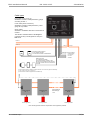
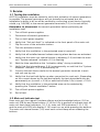
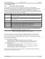
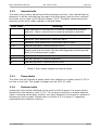
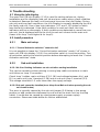
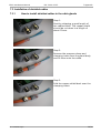
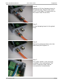
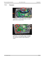
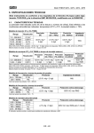
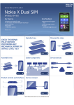
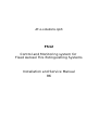
JK e-solutions ApS
FS12
Control and Monitoring system for
Fixed Aerosol Fire Extinguishing Systems
Installation and Service Manual
R6
FS12 Installation Manual
R6 - 2014-02-25
Table of Contents
1 Preface............................................................................................................................3
1.1 Purpose....................................................................................................................3
1.2 Abbreviations...........................................................................................................3
1.3 Terms.......................................................................................................................3
2 General Description........................................................................................................4
2.1 System description..................................................................................................4
2.1.1 System overview..............................................................................................4
3 Overview........................................................................................................................5
3.1 FS12 Main unit.........................................................................................................5
3.1.1 Front panel.......................................................................................................5
3.1.2 PCB...................................................................................................................7
3.2 FS12 Sub unit........................................................................................................10
4 Installation....................................................................................................................12
4.1 Warnings................................................................................................................12
4.2 Prerequisites .........................................................................................................12
4.2.1 Loop cable......................................................................................................12
4.2.2 Power supply..................................................................................................12
4.2.3 Aerosol generator...........................................................................................13
4.2.4 External release buttons / activation switches...............................................13
4.2.5 Detectors........................................................................................................13
4.3 Installation procedure............................................................................................15
5 Service..........................................................................................................................18
5.1 Testing the installation...........................................................................................18
5.2 Main unit indicator test..........................................................................................18
5.3 Localizing faults.....................................................................................................19
5.3.1 Loop faults / Sub units faults..........................................................................19
5.3.2 Internal faults.................................................................................................20
5.3.3 Power faults....................................................................................................20
5.3.4 Detector faults................................................................................................20
6 Trouble shooting...........................................................................................................21
6.1 Using the info display............................................................................................21
6.2 Install procedure....................................................................................................21
6.2.1 Main unit setup...............................................................................................21
6.2.2 Sub unit installation........................................................................................21
6.3 Fault scenarios.......................................................................................................22
6.3.1 The main unit enters fault condition state just after power-up.......................22
6.3.2 Periodic sub unit faults...................................................................................23
6.4 Performing a factory reset.....................................................................................23
6.4.1 Main unit factory reset....................................................................................23
6.4.2 Sub unit factory reset.....................................................................................23
6.5 Debug log..............................................................................................................23
6.5.1 Saving debug log to internal memory............................................................24
6.5.2 Retrieving the debug log................................................................................24
7 Appendix......................................................................................................................25
7.1 Technical data........................................................................................................25
7.2 Screw tightening torques.......................................................................................25
7.3 Installation of shielded cables...............................................................................26
7.3.1 How to install shielded cables in the cable glands.........................................26
7.3.2 Examples........................................................................................................28
8 References....................................................................................................................29
9 Revision history............................................................................................................30
JK e-solutions ApS
2/30
FS12 Installation Manual
R6 - 2014-02-25
1 Preface
1 Preface
This document is the installation manual for the FS12 – Control and Monitoring
System for Fixed Aerosol Fire Extinguishing Systems.
1.1 Purpose
The purpose of this document is to describe installation, service and trouble
shooting of the FS12 system.
Please note that only aspects regarding the FS12 system itself are covered by this
manual. Physical placement of aerosol generators and cables etc. is not handled
as these issues are typically to be specified specifically for each installation.
Daily use of the FS12 system is described in the FS12 User Manual [UM].
1.2 Abbreviations
The abbreviations are used in the Installation Manual:
CSA
Cross Sectional Area
IMO
International Maritime Organization
NC
Normally Closed
NO
Normally Open
PCB
Printed Circuit Board
PE
Protective Earth
1.3 Terms
The following terms are used in the Installation Manual:
Detector
JK e-solutions ApS
Device connected to the detector input. E.g. a smoke, fire or
flame detector, but could also be an electrical switch used as a
manual fire alarm.
3/30
FS12 Installation Manual
R6 - 2014-02-25
2 General Description
2 General Description
2.1 System description
2.1.1
System overview
The purpose of the FS12 system is to control and monitor a number of aerosol
generators mounted on a ship as part of a fire extinguishing systems.
The primary purpose of the FS12 system is to activate the aerosol generators in
event of fire.
The secondary purpose of the FS12 system is to monitor the system itself (e.g.
power supplies, cables and individual system components) and give an alarm if a
fault within the system is detected.
Furthermore, an input is provided for detectors.
To handle single-point power supply failures, the FS12 main unit provides 2 power
supply inputs.
The illustration below contains a schematic overview of the FS12 system:
Smoke detectors
Alarm devices for fire alarm
Power supplies
FS12 main
Alarm devices for system fault warning
Alarm devices for imminent aerosol release
FS12 sub
FS12 sub
FS12 sub
FS12 sub
Aerosol generators
Illustration 1: FS12 system overview
JK e-solutions ApS
4/30
FS12 Installation Manual
R6 - 2014-02-25
3 Overview
3 Overview
3.1 FS12 Main unit
3.1.1
Front panel
1.1 OK indicator
1.2 Release indicator
1.3 Fire alarm indicator
1.4 Fault indicators
1.5 Ventilation button
1.6 Fault handling buttons
1.7 Release button
1.8 Fire alarm buttons
1.1
OK indicator
When the FS12 system is powered on and no faults or fire alarm is
detected, the OK indicator will be lit.
1.2
Release indicator
The Release indicator will be flashing during the activation delay period
and will be permanently on after activation of aerosol generators.
1.3
Fire alarm indicator
The Fire alarm indicator will be on if devices connected to the detector
input (1.21) are active.
1.4
Fault indicators
- Power 1 fault: Power supply voltage is out of range
- Power 2 fault: Power supply voltage is out of range
- Loop 1 fault: Fault detected on Loop 1, e.g. communication errors or no
communication to sub units.
- Loop 2 fault: Fault detected on Loop 2, e.g. communication errors or no
JK e-solutions ApS
5/30
FS12 Installation Manual
R6 - 2014-02-25
3 Overview
communication to sub units.
- Sub unit fault: Fault reported by sub units, e.g. bad loop cable
connections, bad connection to aerosol generator or internal sub unit
faults
- Internal fault: Fault detected in main unit, e.g. internal hardware or
software error, activation switch connection fault
- Detector fault: Fault detected on detector input, e.g. broken cable.
Note that the Detector fault indicator will be lit shortly when
acknowledging a fire alarm. This is due to the detector power being
removed for at short period to reset the connected detectors.
1.5
Ventilation button
If connected to the FS12 Main unit, the ventilation system in the
protected area will be shut off if aerosol generators are activated. By
pressing the Ventilation button, the ventilation system can be restarted
after fire extinction.
1.6
Fault handling buttons
If a fault is detected, the corresponding indicator is lit and the internal
buzzer and external fault warning device is turned on (if connected). By
pressing the Fault Warning Silence button the internal buzzer and the
external fault warning device may be turned off. When the fault
condition has been remedied, the fault indicator may also be turned off
by pressing the Fault Warning Acknowledge button.
1.7
Release button
In event of fire lift the cover and turn the Release button clockwise to
activate the aerosol generators. Note that the aerosol generators will be
activated even if the Release button is turned back (counter clockwise).
1.8
Fire alarm buttons
If fire or smoke is detected by detector(s) connected to the FS12 system,
the Fire alarm indicator is lit and the internal buzzer and external fire
alarm device is turned on. By pressing the Fire Alarm Silence button the
internal buzzer and the external fire alarm device may be turned off.
When the fire or smoke is no longer present, the fire alarm may be reset
by pressing the Fire Alarm Acknowledge button.
JK e-solutions ApS
6/30
FS12 Installation Manual
3.1.2
R6 - 2014-02-25
3 Overview
PCB
1.9. Internal buzzer
1.24. Fire Alarm output
1.25. Smoke detector input
1.26. Fault warning output
1.27. Release warning output
1.28. Loop 1
1.29. Loop 2
JK e-solutions ApS
7/30
FS12 Installation Manual
R6 - 2014-02-25
3 Overview
1.9
Internal buzzer
The internal buzzer is a supplement to the external alarm and warning
devices. It also gives audible feedback to the user, e.g. during
installation. Generally successful operations are marked by a short bleep
(100ms) and failed operations are marked by a long bleep (400ms)
1.10
Info display
The info display is used for setting values during installation and for pin
pointing faults.
1.11
Loop 2 PCB indicator
When the Loop 2 PCB indicator is lit, the value shown in the Info display
(1.10) is related to loop 2.
1.12
Loop 1 PCB indicator
When the Loop 1 PCB indicator is lit, the value shown in the Info display
(1.10) is related to loop 1.
1.13
Install PCB indicator
The Install PCB indicator is used to indicate “system not installed” and
“install mode active”
1.14
Internal activation switch connector
Connector for the internal activation switch
1.15
Front panel connector
Connector for the front panel.
1.16
PCB buttons
The buttons on the main unit PCB are used for installation and fault
finding. During installation the Up and Down button are used for setting
values and the install button is used for stepping through the install
procedure. During fault conditions, pressing the Up button will make the
Info Display (1.10) display an error code related to the current fault
condition.
1.17
Loop2 power supply fuse. Type: 2.5A slow blow
1.18
Loop1 power supply fuse. Type: 2.5A slow blow
1.19
Power supply 2 fuse. Type: 5A Anti surge
1.20
Power supply 1 fuse. Type: 5A Anti surge
1.21
Power supply terminals. Connect PSU1 and PSU2 to independent power
supplies. The ground terminal may be connected to the ship hull or PE
connector. The ground terminal is connected to the main unit enclosure
metallization and the metal cable glands.
1.22
External activation switch terminal
Connect any external activation switch to this terminal. Each external
activation switch must be fitted with a 47KΩ (1%) resistor in parallel with
the contact set. FS12 release buttons are pre-mounted with this resistor.
1.23
Ventilation terminal
Potential free relay output for the ventilation system. The ventilation
system in the protected area should be interruptible by the FS12 system
to facilitate automatic shut down in case of activation of aerosol
JK e-solutions ApS
8/30
FS12 Installation Manual
R6 - 2014-02-25
3 Overview
generators. The NC/NO designations apply when the main unit is not
powered and during activation. During normal operation, the NO contact
set will be closed.
1.24
Fire alarm output
Potential free relay output for Fire alarm sirens and similar devices. The
relay contact set will be shorted in case of an active fire alarm.
1.25
Detector input
Connect up to 8 detector units1 (in parallel) to this input. Observe
detector characteristics given in section 4.2.5 . 24V (unregulated) is
supplied to the detectors on the terminals. The detector cable must be
terminated by a 10KΩ resistor at the last detector. If no detectors are
used, A 10KΩ resistor must be fitted directly at the terminal. The resistor
is fitted ex factory.
Please notice that an active detector input/fire alarm will not
automatically lead to activation of the aerosol generators. In all cases
this must be done by turning the activation switch.
1.26
Fault warning output
Potential free relay output for fault warning devices (e.g. sirens or
beacons). The relay contact set will be shorted if a fault condition is
detected by the main unit. Pressing the Fault warning silence button
(1.6) will open the relay contact set.
1.27
Release warning output
Potential free relay output for aerosol release warning devices (e.g.
sirens or beacons). Aerosol release warning devices must be mounted in
the protected area. The relay contact set will be shorted when during the
activation delay period (from turning a activation switch until all aerosol
generators have been activated that is).
1.28
Loop 1 terminal
Connect loop 1 cable to this terminal. The individual terminals (A1, B1,
C1, D1) must be connected to the corresponding terminals on the sub
unit(s) (2.2).
1.29
Loop 2 terminal
Connect loop 2 cable to this terminal. The individual terminals (A2, B2,
C2, D2) must be connected to the corresponding terminals on the sub
unit(s) (2.4).
If a heavy duty cable is used for the loops, it may be advantageous to
connect a small length (say shorter than 1m) of a smaller gauge cable to
the main unit loop terminal and the join the cables in a separate
junction box.
1 Switches used for manual fire alarm may also be connected to the detector input, as long as
characteristics given in section 4.2.5 are respected.
JK e-solutions ApS
9/30
FS12 Installation Manual
R6 - 2014-02-25
3 Overview
3.2 FS12 Sub unit
2.1. Aerosol generator terminal
2.2. Loop 1 terminal
2.3. Indicators
(Loop1, Loop2, Ok, activator)
2.4. Loop 2 terminal
2.5. Install button*
2.6. Install jumper
*Install jumper is not
used on PCB rev. E14
and newer.
2.1
Aerosol generator terminal
Connect the aerosol generator to this terminal. Observe characteristics
given in section 4.2.3 .
2.2
Loop 1 terminal
Connect loop 1 cable passing through or ending at this sub unit.
Tightening the terminal screws with the correct torque is important to
ensure solid electrical connections, please refer to section 7.2 on page
25.
2.3
Indicators
The indicators reflects the current state of the sub unit.
- OK indicator
- Permanently on: Sub unit installed and in no-fault state.
- Flashing fast (5Hz): Sub unit not installed.
- Flashing slowly (1.25Hz): Sub unit installation in progress.
- Loop 1 and Loop 2 indicators
- Permanently on: Power supply fault on the loop.
- Flashing slowly (1.25Hz): Communication error on the loop.
- Periodic short flash (7.5s): Communication with main unit OK.
- Activator indicator
- Flashing fast (5Hz): Bad connection to aerosol generator /
aerosol generator has too high resistance.
JK e-solutions ApS
10/30
FS12 Installation Manual
R6 - 2014-02-25
3 Overview
(If installation in progress: Install jumper (2.6) is not mounted)
- Flashing slowly (1.25Hz): Connection to aerosol generator
shorted / aerosol generator has too low resistance.
- Permanently on: Aerosol generated has been activated/released.
Internal sub unit faults are indicated by Loop1, Loop2 and activator
indicators flashing fast (5Hz). In this case, the OK indicator will be off.
2.4
Loop 2 terminal
Connect loop 2 cable passing through or ending at this sub unit.
Tightening the terminal screws with the correct torque is important to
ensure solid electrical connections, please refer to section 7.2 on page
25.
2.5
Install button
The Install button is only used during installation. Refer to section 4.3 for
further details.
2.6
Install jumper
The Install jumper is only used during installation. Refer to section 4.3 for
further details. Please note that the install jumper is not available on
sub-unit PCB revision E14 and newer (serial no. S1402-xxx and higher).
JK e-solutions ApS
11/30
FS12 Installation Manual
R6 - 2014-02-25
3 Overview
4 Installation
Please see overview drawing on page 14.
4.1 Warnings
Warning
Never work on the electrical
connections of the FS12 system
while power supplies are turned on.
Aerosol generators may be activated
unintentionally if doing so.
4.2 Prerequisites
4.2.1
Loop cable
The cable used for connections between the main unit and the sub unit(s) must
be 4-conductor shielded marine type fire proof cable according to IEC60331
[1270]. Local regulations or classification society requirements may also apply.
The total DC-resistance of each conductor in the loop cable must not be higher
than 3.5Ω at 25°C. Maximum loop cable lengths for typical cable gauges are
given in the table below:
Cable CSA
Max length
0.75mm2
145m
1.00mm2
195m
1.50mm2
300m
Table 1: Max loop cable length for typical cable gauges
(The loop cable length is measured from the main unit to the last sub unit on the
loop)
The capacitance of the cable must not exceed 100nF/km.
4.2.2
Power supply
The main unit must be powered by two independent 24V power supplies. The
power supply voltage must be 24V nominal -25%/+30%. Please observe local
regulations and classification society requirements regarding power sources.
The power supplies must be connected using shielded cable of the same CSA as
used for the loops. The power supply requirements apply at the terminals of the
main unit. (Observe voltage drop in the power supply cables). If the power supply
cables are longer than 10 meters, the length exceeding 10 meters must be
subtracted from the maximum loop cable length given in Table 1. For example, if
JK e-solutions ApS
12/30
FS12 Installation Manual
R6 - 2014-02-25
4 Installation
the longest power supply cable is 20 meters of 0.75mm2 gauge cable, the
maximum loop cable length must be reduced to 135 meters.
4.2.3
Aerosol generator
The electrical activation unit in the aerosol generator must have an electrical
resistance of 1.5Ω – 3.0Ω.
The FS12 system supports up to 50 aerosol generators (1 sub unit is needed for
each aerosol generator.)
4.2.4
External release buttons / activation switches
All external release buttons / activation switches must be fitted with a 47KΩ (1%)
resistor in parallel with the contact set. FS12 release buttons are pre-mounted
with this resistor.
4.2.5
Detectors
Smoke/fire/flame detectors or other devices with the following characteristics are
supported:
–
Alarm resistance: 250-1000Ω
–
No-alarm resistance: > 480kΩ (<50µA @ 24V)
Up to 8 detector devices may be connected to the FS12 Main unit.
Please note that the detector input is not designed to be shorted. If an output
with too low resistance is to be connected to the detector input, a series resistor
must be mounted in series with the output.
JK e-solutions ApS
13/30
FS12 Installation Manual
R6 - 2014-02-25
4 Installation
Cable types
Loop cable (Loop 1/Loop 2):
Shielded 4-conductor cable (IEC 60331), gauge
according to table 1.
Power cable (Power 1/Power 2):
Shielded 2-conductor cable (IEC 60331), same
gauge as loop cables.
Other cables:
Shielded or unshielded. Number of conductors as
needed.
The shield in shielded cables must always be
mounted securely in metal glands or clamps in
both ends.
Power 1
Power 2
Loop 1
External activation switches:
0 to 5 switches possible.
47K termination resistor on each switch.
Loop 2
Potential free relay outputs
Release Warning
Fault Warning
Fire Alarm
Ventilation
Detector devices:
0 to 8 detectors possible.
10K end-termination resistor on last
device. End-termination resistor must be
mounted on Main unit when no detectors
are used.
End-termination resistors (120R) mounted on last sub unit on each loop (B and C terminals).
(Loop 1: Sub unit N, Loop 2: Sub unit 1)
(End termination resistors supplied with FS12 Main unit)
FS12 Sub Unit
No. 1
FS12 Sub Unit
No. 2
Aerosol generator
Aerosol generator
Total number of
Sub units (N):
1-50
FS12 Sub Unit
No. N
Aerosol generator
Each aerosol generator and sub unit placed as close together as possible.
JK e-solutions ApS
14/30
FS12 Installation Manual
R6 - 2014-02-25
4 Installation
4.3 Installation procedure
The following is a general installation procedure. Variations may apply to specific
systems. Placement of all equipment should appear from construction drawings.
Please note that the FS12 install procedure described in step 13 below MUST be
performed after installing the system, cables etc. on the ship. This is because
cable connections and general basic performance of the system is checked as
part of the procedure.
1.
Mount the FS12 Main unit outside the protected area.
2.
Mount extra FS12 release button(s) if necessary.
3.
Mount FS12 sub unit(s) as close to aerosol generators as possible in the
protected area.
4.
Mount alarm/warning devices.
5.
Mount detector devices if applicable.
6.
Mount and connect loop cables between the main unit and the sub unit(s).
The two loops must be placed as far apart as possible to reduce the risk of
damage to both loops. The first sub unit connected to the main unit Loop 1
terminal (1.28) must be the last sub unit connected to the main unit Loop 2
terminal (1.29) and vice versa. Make sure that the cable connected to the
main unit Loop 1 terminal (1.28) is connected to the Loop 1 terminal (2.2)
on all sub units. The termination resistors mounted in the main unit's Loop
terminals (1.28/1.29) must be moved to the last sub unit on each loop,
between the B and C connectors of the Loop terminals (2.2/2.4). Note that
it is imperative that the shield conductors are connected securely to the
metal glands on the sub units(s) and the main unit. Otherwise noise from
other electrical installations may interfere with the system and cause
random fault.
7.
Mount and connect cables for additional FS12 release buttons,
alarm/warning devices, detector devices and ventilation in the protected
area. The detector termination resistor mounted in the main unit's detector
terminal (1.25) must be moved to the last detector on the detector cable
(farthest away from the main unit).
8.
Mount and connect power supply cables. The shield conductors of the
power supply cables must be connected to the metal glands on the mainunit; see notes about shielding above.
9.
Check all connections
10.
Turn on both power supplies
11.
All indicators on the main unit will be lit for at short time and the internal
buzzer bleeps shortly.
12.
“System not installed” is indicated by System OK (1.1) and sub Unit Fault
(1.4) indicators on the main unit front panel flashing alternately. Install
indicator (1.13) on main unit PCB will also be flashing. Sub units indicate
“not installed” by rapid flashing (5Hz) with OK indicator (2.3)
13.
Go through the FS12 install procedure. The main unit front panel must be
connected but not mounted on the main unit.
JK e-solutions ApS
15/30
FS12 Installation Manual
R6 - 2014-02-25
4 Installation
13.1.
Press the Install button (1.16) on the main unit PCB for 0.5s.
13.2.
Install procedure running indicated by main unit PCB Install
Indicator permanently lit.
13.3.
Set number of external release buttons/activation switches
a)
The main unit PCB Info Display (1.10) alternates between “EA”
(=External Activation”) and the set number of external
activation switches.
b)
Set the number of installed external activation switches by
pressing the Up and Down buttons (1.16) on the main unit PCB.
c)
When the correct number of installed external activation
switches has been set, proceed by pressing the Install button
(1.16) for 0.5s.
13.4.
Control correct function of activation switches.
a)
“cA” (=control Activation switches) is displayed in the main unit
PCB Info Display (1.10).
b)
Control correct function of each activation switch (external
activation switches as well as the internal activation switch) by
turning each of them on by turn. The System Released indicator
(1.2) on the main unit front panel must be lit when an activation
switch is turned on.
c)
When all activation switches have been found to function
correctly, proceed by pressing the Install button (1.16) for 0.5s.
13.5.
Set activation delay
a)
The main unit PCB Info Display (1.10) alternates between “Ad”
(= Activation delay”) and the set activation delay. The
activation delay is displayed in 10s units, e.g. 02=20s and
10=100s
b)
Set the activation delay by pressing the Up and Down buttons
(1.16) on the main unit PCB. The activation delay can be set
between 20s and 120s. The activation delay should be set
according to the time needed to evacuate the protected area.
c)
When the correct activation delay has been set, proceed by
pressing the Install button (1.16) for 0.5s.
13.6.
Setup sub unit IDs
a)
For the communication between the main unit and the sub
unit(s) to work, each sub unit must have a unique id, which will
be setup in this step. An automatic test of the loop cables is
also done at the same time by the system.
b)
The main unit PCB Info Display (1.10) displays the number of
installed sub units. Initially 0 sub units are installed.
c)
All connected sub units should indicate “Ready for install” by
slow flashing (1.25Hz) the OK indicator (2.3).
d)
The first sub unit on the Loop 1 cable must be installed first,
thereafter the next sub unit on the Loop 1 cable and so on until
JK e-solutions ApS
16/30
FS12 Installation Manual
R6 - 2014-02-25
4 Installation
the last sub unit has been installed. The last sub unit installed
will then be the sub unit that is first on the Loop 2 cable.
e)
Move the sub unit Jumper (2.6) to Install Mode. (This does NOT
apply to sub-units with PCB revision E14 and newer)
f)
Press the sub unit Install button (2.5) to install the sub unit.
g)
If both loop cables are connected correctly the main unit should
emit a short bleep (100ms) and the sub unit count in the main
unit PCB Info Display (1.10) is incremented. The sub unit OK
indicator (2.3) will be permanently on. If the sub unit for some
reason cannot be installed, the main unit emits a long bleep
(400ms) and the main unit PCB Info Display (1.10) is not
incremented. The indicators on the sub unit (2.3) should
provide information about the error reason. Please refer to
section 6.2.2 on page 21 for further details.
h)
Move the sub unit Install Jumper (2.6) to Normal mode. (This
does NOT apply to sub-units with PCB revision E14 and newer)
i)
Repeat steps e-h for all sub units.
13.7.
When all sub units have been installed verify that the sub unit
count in the main unit PCB Info Display (1.10) corresponds to the
total number of sub units in the system.
14.
End installation by pressing the main unit PCB Install button (1.16) for 0.5s.
15.
The system should now be functioning normally, except sub unit fault is
reported on the main unit front panel, because the aerosol generator(s) are
not connected to the sub unit(s).
16. Turn off both power supplies.
17.
Connect the aerosol generator(s) to the sub unit(s)'s Aerosol Generators
terminal (2.1).
18.
Turn on both power supplies.
19.
The system should now be functioning normally, System OK is reported on
the main unit front panel.
JK e-solutions ApS
17/30
FS12 Installation Manual
R6 - 2014-02-25
5 Service
5 Service
5.1 Testing the installation
All FS12 installation must be tested to verify that activation of aerosol generators
is possible. The aerosol generators will not actually be activated, but the
installation's ability to do so will be verified by connecting a test device (typically
a bulb, e.g. 24V/5W) to the aerosol generator terminals (2.1) in the sub unit(s).
Remember to disconnect the aerosol generators before performing an
installation test!
1.
Turn off both power supplies
2.
Disconnect all aerosol generators
3.
Turn on both power supplies
4.
Verify that “Sub unit fault” is indicated on the front panel of the main unit.
5.
Flip the cover of the activation button.
6.
Turn the activation button.
7.
Verify that the ventilation in the protected area is turned off.
8.
Verify that all installed aerosol release warning alarm devices are activated.
9.
Verify that the main unit internal buzzer is bleeping (1.9) and that the main
unit ”System released” indicator (1.2) is flashing.
10.
Wait the time specified as the “activation delay” during installation.
11.
Verify that the internal buzzer (1.9) is permanently on and that the ”System
released” indicator (1.2) is permanently on.
12.
Connect the test device (bulb) to the aerosol generator terminals in each
sub unit one by one.
13.
Verify that the test bulb lights up when connected to a sub unit. (Depending
on the current drawn by the test device/bulb, the test device/bulb may be
permanently on (current < 0.5A) or switched off after 0.5s (current > 0.5A)
14.
Verify that the ventilation in the protected area can be restarted by
pressing the “Restart ventilation” button.
15.
Turn off both power supplies.
16.
End of test.
5.2 Main unit indicator test
Press main unit front panel Fire alarm silence and acknowledge buttons (1.8) or
main unit PCB Up and Down buttons (1.16) for 0.5s to perform a indicator test. All
main unit front panel indicators (1.1-1.4), main unit PCB indicators (1.11-1.13)
and the main unit PCB info display (1.10) must turn on while pressing the buttons.
The main unit internal buzzer (1.9) must emit a short bleep when releasing the
buttons.
JK e-solutions ApS
18/30
FS12 Installation Manual
R6 - 2014-02-25
5 Service
5.3 Localizing faults
5.3.1
Loop faults / Sub units faults
If a loop fault or sub unit fault is indicated on the main unit front panel,
information about the fault can be obtained from the main unit PCB Info Display
(1.10). The Info Display will be showing the id of the affected sub unit. By
pressing the main Unit PCB Up button (1.16) just below the Info Display, an error
code can be obtained if available. The table below shows the meaning of the error
codes related to loop faults and sub unit faults:
Error code
Meaning
61
Connection to aerosol generator shorted / aerosol generator has
too low resistance.
62
Bad connection to aerosol generator / aerosol generator has too
high resistance.
63
Loop 1 negative power supply bad (Conductor Dx)
64
Loop 1 positive power supply bad (Conductor Ax)
65
Loop 2 negative power supply bad (Conductor Dx)
66
Loop 2 positive power supply bad (Conductor Ax)
67
Sub unit is in install mode
70-7A
Sub unit internal hardware fault. Power cycling the FS12 system
may solve the problem. If this is not the case, the sub unit PCB
must be replaced. Also see section 6.3.2.
Table 2: Error codes related to sub unit faults.
If an error code is not shown, the fault is probably related to the loop cables.
Check all loop cable connections between the fault sub unit and the main unit.
If the fault condition was initially detected by a sub unit, it will also be reflected
by the sub unit indicators:
Loop 1 and Loop 2 indicators
- Permanently on: Power supply fault on loop in question.
- Flashing slowly (1.25Hz): Communication error on loop in question.
- Periodic short flash (7.5s): Communication with main unit OK.
- Activator indicator
- Flashing fast (5Hz): Bad connection to aerosol generator / aerosol
generator has too high resistance.
- Flashing slowly (1.25Hz): Connection to aerosol generator shorted /
aerosol generator has too low resistance.
Internal sub unit faults are indicated by Loop1, Loop2 and activator indicators
flashing fast (5Hz) simultaneously.
JK e-solutions ApS
19/30
FS12 Installation Manual
5.3.2
R6 - 2014-02-25
5 Service
Internal faults
The main unit contains advanced self-monitoring functions. If an internal fault is
detected, it will be indicated on the main unit front panel, and an error code will
be shown on the main unit PCB Info Display (1.10). The table below shows the
meaning of the error codes related to internal faults:
Error code
Meaning
A
Fault detected on connection to internal or external activation
switches. Check connections to external activation switches.
81
One of the internal processors has restarted during operation.
82
Hardware fault detected on detector input.
84
Hardware fault detected on activation switch input.
85-87
Internal processor communication error.
88
Hardware fault detected on power supply monitoring circuit.
Please note that this fault can also be triggered by earth/ground
fault in the ships power supply.
89
Internal memory checksum failure.
8A
Internal memory contents mismatch
8b
Internal processor communication error.
8c
Internal software error.
Table 3: Error codes related to internal faults.
5.3.3
Power faults
The main unit will indicate a power fault if the voltage on a power input (1.21) is
too low or too high. The supply voltage must be 18 to 31 volts.
5.3.4
Detector faults
A detector fault will be indicated on the main unit front panel, if a wrong load is
detected on the detector input (1.25). This may be caused by a broken detector
cable, a missing termination resistor, too many detectors connected or detectors
drawing too much power. Please refer to section 4.2.5 on page 13 regarding
requirements for detector devices.
JK e-solutions ApS
20/30
FS12 Installation Manual
R6 - 2014-02-25
6 Trouble shooting
6 Trouble shooting
6.1 Using the info display
The main unit PCB Info Display (1.10) is used for setting values etc. during
installation and for displaying sub unit ids and error codes when a fault condition
is detected. Remove the main unit front panel to access the Info Display. During
sub unit and Loop fault conditions, the Info Display is normally displaying the id of
the faulty sub unit. One of two loop indicators (1.11 and 1.12) shows on which
loop the fault is detected. If the fault condition is a sub unit fault, the loop
indicators will be on alternately. If fault conditions are detected on more than one
sub unit, the id displayed will be the id of the sub unit closest to the main unit
(lower id for loop 1 and higher id for loop 2).
6.2 Install procedure
6.2.1
Main unit setup
6.2.1.1 “Control Activation switches” cannot be left
It is not possible to leave the “Control Activation switches” mode (“cA” shown in
main unit PCB info display (1.10)) if an activation switch is in active position. Turn
all activation switches to inactive position before attempting to leave the “Control
Activation switches” state.
6.2.2
Sub unit installation
6.2.2.1 No lit or flashing indicators on sub unit after starting installation
This can be caused by either missing or wrong loop cable connections or main
unit failure on Loop 1 connection.
Check Loop 1 cables, main unit fuse (F2 (1.18)) and voltage between A(+) and
D(-) on main unit Loop 1 terminal (1.28) and on sub unit Loop 1 terminal (2.2).
The voltage should be 1-2 volts lower than the supply voltage.
6.2.2.2 Sub unit cannot be installed (error bleep from Main unit when pressing the sub
unit install button)
This error is typically caused by the sub unit jumper (2.6) being in the wrong
position or bad connections between the sub unit at the main unit (on the loop
cable). It could also be caused by a bad power supply or power supply
connection. Please see table below for further elaboration.
JK e-solutions ApS
21/30
FS12 Installation Manual
Error indication
R6 - 2014-02-25
Probable causes
6 Trouble shooting
Solutions
Main unit front panel
- Sub unit fault
Sub unit
- No error indication
Bad data communication
between main unit and
sub unit.
Main unit front panel
- Sub unit fault
Sub unit
- Loop 1 or Loop 2
indicator on
Voltage drop in loop cable Check loop cables and
too high.
connections.
Check loop cable Ax and
Too low supply voltage at Dx conductor
sub unit when supplied by connections.
indicated loop cable.
Check length and gauge
of loop cable (please refer
Typically caused by bad
to section 4.2.1 regarding
loop cable connections
loop cable requirements.
(Ax or Dx conductor), too
long loop cables or
undersized loop cables.
Blown loop fuse in main
unit (1.17 and 1.18).
Check loop cables and
connections:
Loop 1 main unit terminal
(1.28) must be connected
to loop 1 terminals on all
sub units (2.2) and vice
versa for the loop 2 cable.
Check Bx, Cx and Dx
conductor connections.
Check fuses and replace if
necessary.
Main unit front panel
- Sub unit fault
Sub unit
- Activator indicator
flashing rapidly (5Hz)
Sub unit install jumper
Move sub unit install
(2.6) not in “Install mode” jumper (2.6) to “Install
position.
mode”.
Main unit front panel
- Power supply fault
One or both power
supplies or power supply
connection(s) are bad.
Check power supplies,
connections and fuses.
Main unit front panel
- Internal fault
Internal fault in the main
unit.
Try installing sub unit
again (Press sub unit
install button (2.5)).
Contact dealer if problem
persists.
Press the sub unit install button (2.5) again after resolving the error.
6.3 Fault scenarios
6.3.1
The main unit enters fault condition state just after power-up
If the main unit enters a fault condition immediately after power-up (before the
normal indicator test), it may be caused by corruption of the internal memory.
The Internal fault indicator and the loop 1 and/or loop 2 fault indicators will be
flashing rapidly. This fault condition may be caused by unstable power supplies or
turning the power on and off rapidly.
JK e-solutions ApS
22/30
FS12 Installation Manual
R6 - 2014-02-25
6 Trouble shooting
The fault may be remedied by performing a factory reset of the main unit (see
section 6.4 ). The FS12 installation procedure needs to be performed again after
doing a factory reset.
6.3.2
Periodic sub unit faults
Periodic sub unit fault (fault codes 70-7A) may occur due to bad cabling,
especially if the shields are not terminated correctly. Check that all cable shields
are terminated securely in the cable glands. This applies to both loop cables and
power supply cables.
6.4 Performing a factory reset
It is possible to reset the internal memory of the main unit and the sub unit(s).
This means resetting values set during the installation procedure to factory
defaults. After performing a factory reset, the installation procedure must be
performed again.
6.4.1
Main unit factory reset
Notice: All sub unit connected to the main unit will also do a factory reset if the
main unit is operating normally. Disconnect both loop cables if this is not required.
If the main unit is fault condition as described in section 6.3.1 , sub unit may not
be reset.
1. Turn off power
2. Remove the front panel
3. Press and hold the main unit PCB Install button (1.16)
4. Turn on power
5. Wait for bleep from internal buzzer (1.9)
6. Release the main unit PCB Install button.
6.4.2
Sub unit factory reset
1. Turn off power
2. Remove the sub unit lid
3. Press and hold the sub unit Install button (2.5)
4. Turn on power
5. Wait for light in all sub unit indicators
6. Release the sub unit Install button.
6.5 Debug log
The main unit continuously outputs a debug log from the internal processors. The
debug log may be viewed by connecting the main unit to a pc using a USB-TTL
cable (“FTDI TTL-232R-3V3“). A terminal program (e.g. HyperTerminal og
JK e-solutions ApS
23/30
FS12 Installation Manual
R6 - 2014-02-25
6 Trouble shooting
TeraTerm) is needed on the pc. The debug log may contain useful information for
debugging faults etc. The latest information in the debug log may be saved to
internal memory thereby saving it for future reference. This may be useful when
debugging periodic faults that may be hard to find when the ship is in harbour. In
this case the debug log should be saved just after occurrence of a fault.
6.5.1
Saving debug log to internal memory2
1. Press and hold both Silence buttons on front panel (1.6 and 1.8, Fault
warning silence and Fire alarm silence).
2. Wait for buzzer beep.
3. Release Silence buttons.
4. Wait for short beep from buzzer.
5. The debug log is now saved in internal memory.
Please note that any previously saved debug log will be overwritten when saving
a new debug log.
6.5.2
Retrieving the debug log
If there is a saved debug log in internal memory, it will be output by the main unit
at power-up. Alternatively output of a saved debug log may be started by
pressing “p” in the terminal program (e.g. TeraTerm) when connected to the main
unit.
2 This applies only to main unit SW V1.01.00 and newer. On older SW versions all three PCB
buttons must be pressed to start saving the debug log.
JK e-solutions ApS
24/30
FS12 Installation Manual
R6 - 2014-02-25
7 Appendix
7 Appendix
7.1 Technical data
Supply voltage:
2x 24VDC nominal (-25% / +30%)
Relay outputs:
24VDC nominal, Max 8A
Nominal current, Main unit:
Nominal current, Sub unit:
During activation, total system:
< 500mA
< 15mA
< 3.5A
Weight, Main unit:
Weight, Sub unit:
1.25kg
0.60kg
Dimensions, Main unit (HxWxD),
excluding cable glands:
Dimensions, Sub unit (HxWxD),
excluding cable glands:
179.2mm x 199mm x 109.5mm
80mm x 125mm x 57mm
7.2 Screw tightening torques
Ensuring correct screw tightening torques is important to have solid electrical
connections and vibration-proof joints.
Terminal / joint
Minimum torque
Maximum torque
Main unit front panel to enclosure
0.55Nm
0.65Nm
Main unit PCB to enclosure
0.65Nm
0.75Nm
Sub unit loop terminals
0.5Nm
0.6Nm
Sub unit PCB to enclosure
0.9Nm
1.1Nm
Sub unit enclosure lid to enclosure
1.4Nm
1.5Nm
JK e-solutions ApS
25/30
FS12 Installation Manual
R6 - 2014-02-25
7 Appendix
7.3 Installation of shielded cables
7.3.1
How to install shielded cables in the cable glands
Step 1:
Start by stripping a good length of
the cable sheath. The copper shield
should be cut down to a length of
about 15mm.
Step 2:
Remove the pressure dome and
clamping insert from the gland body
and fit them onto the cable.
Step 3:
Fold the copper shield back over the
clamping insert.
JK e-solutions ApS
26/30
FS12 Installation Manual
R6 - 2014-02-25
7 Appendix
Step 4:
Prepare to fit the clamping insert in
the gland body. Observe the small
notch in the body. The protrusion on
the insert must fit into this.
Step 5:
Fit the clamping insert in the gland
body.
Step 6:
Mount the pressure dome onto the
gland body and tighten it.
Step 7:
The cable shield is now correctly
installed in the cable gland. The
inner conductors may now be
connected to the terminals.
JK e-solutions ApS
27/30
FS12 Installation Manual
7.3.2
R6 - 2014-02-25
7 Appendix
Examples
Illustration 2: Good connection, the shield
conductor is connected inside the cable
gland, all the way round.
Illustration 3: Bad connection, the shield
conductor is connected using a "pig-tail".
Due to this, the shield provides virtually
no protection against high-frequency
noise.
JK e-solutions ApS
28/30
FS12 Installation Manual
R6 - 2014-02-25
8 References
8 References
The following documents are referenced in the Installation manual:
Ref.
Document
Date / Revision
1270
IMO MSC.1/Circ.1270
4 June 2008
UM
FS12 User Manual
R1 2011-08-24
JK e-solutions ApS
29/30