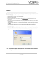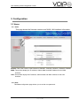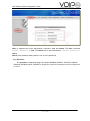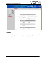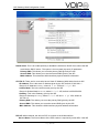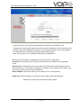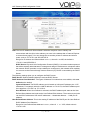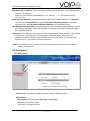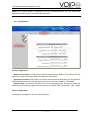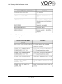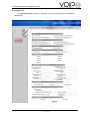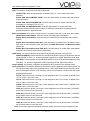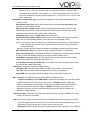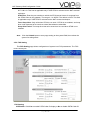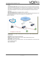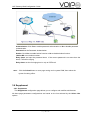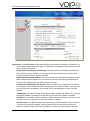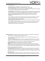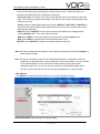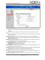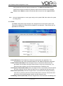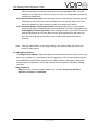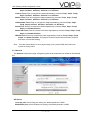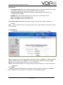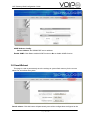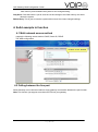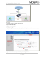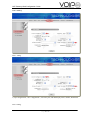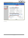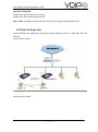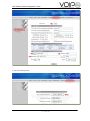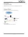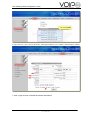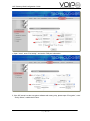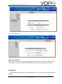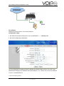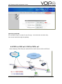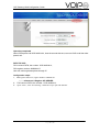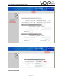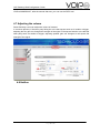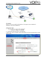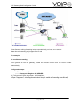
1
VoIP Gateway Web Configuration Guide for
GW0227,
GW0320, GW0321,
GW0429,
GW0620
VoIP Gateway Web Configuration Guide
Content
1. Introduction ........................................................................................................................................... 4
1.1 Scope ............................................................................................................................................ 4
1.2 Audience ...................................................................................................................................... 4
1.3 Document structure .................................................................................................................. 4
1.4 Key features ................................................................................................................................ 4
2. Login........................................................................................................................................................ 6
3. Configuration ........................................................................................................................................ 7
3.1 Home ............................................................................................................................................. 7
3.1.1 Index................................................................................................................................... 7
3.1.2 User .................................................................................................................................... 7
3.1.2 Provision ........................................................................................................................... 8
3.2 WAN ............................................................................................................................................... 9
3.2.1 Wan-configure ................................................................................................................. 9
3.2.2 Virtual-server .................................................................................................................. 11
3.3 LAN .............................................................................................................................................. 13
3.4 Encryption ................................................................................................................................. 15
3.4.1 Policy Select .................................................................................................................. 15
3.4.1 Configuration ................................................................................................................. 16
3.5 Voice............................................................................................................................................ 17
3.5.1 FXS Setting..................................................................................................................... 17
3.5.2 Advanced ........................................................................................................................ 19
3.5.3 FXO Setting .................................................................................................................... 22
3.6 Supplement ............................................................................................................................... 24
3.6.1 Supplement .................................................................................................................... 24
3.6.2 Affixture........................................................................................................................... 27
3.7 Service ........................................................................................................................................ 28
3.7.1 Service Provider............................................................................................................ 28
3.7.2 Login Account ............................................................................................................... 30
3.7.3 Timer ................................................................................................................................ 32
3.7.4 Ring&Tone Setting ....................................................................................................... 33
3.7.5 General ............................................................................................................................ 35
3.7.6 Password ........................................................................................................................ 36
3.7.7 AVMP ............................................................................................................................... 36
3.8 Save&Reboot ............................................................................................................................ 37
4. Solid example in function ................................................................................................................ 38
4.1 Multi-network access method............................................................................................... 38
4.2 Calling between the line port ................................................................................................ 38
Page 2of 60
VoIP Gateway Web Configuration Guide
4.3 Point-To-Point Call .................................................................................................................. 43
4.4 Register SIP server .................................................................................................................. 46
4.5 Router ......................................................................................................................................... 49
4.6 PSTN to VOIP call / VOIP to PSTN call ............................................................................... 51
4.7 Adjusting the volume .............................................................................................................. 55
4.8 Hotline ......................................................................................................................................... 55
4.9 Call forwarding ......................................................................................................................... 57
4.10 Factory reset function .......................................................................................................... 60
Page 3of 60
VoIP Gateway Web Configuration Guide
1. Introduction
The GW0227, GW0320, GW0321, GW0429, GW0620 serial products are based on Public Switched Telephone
Network (PSTN) handset-to-Ethernet adaptor that enables traditional telephone devices to operate as Internet
Protocol (IP) devices. They typically act as a residential gateway, eventually providing Internet Telephony
capability.
They have a high data processing capability, support the standard SIP Protocol, supports popular voice-codec
including G.729 and G.711 (A-law and U-law), and are interoperable with various third party SIP end user
devices. Also supply the easy flexible supplement business. All setup and provisioning are accomplished via a
simple Web interface.
This document provides the descriptions and operation for the gateway serial’s Web configuration. Both basic and
advanced configurations of network and telephony are described.
1.1 Scope
This manual describes the web configuration and operation of the family products. The FXO port is connected to
PSTN network. The FXS port can directly connects the terminal phone with the internet over a wide area network
(WAN) connection and with a host or a HUB over a local area network (LAN) connection. To help the reader
understand more about the gateway serial, some useful materials are appended at the end of manual.
1.2 Audience
The target audiences of this document are the gateway serial’s customers who use the family of products with
VoIP capability. It assumes the reader has a basic knowledge of VoIP networking and telephony.
1.3 Document structure
Chapter 1, Introduction, provides a brief introduction to the user.
Chapter 2, Login, Provides how to login.
Chapter 3, Configuration, Describes some web pages of the configuration menu and allows user to view
update and save the current configuration.
1.4 Key features
Supports SIP 3261 (RADVISION SIP stack), TCP/UDP/IP, RTP/RTCP, HTTP, ICMP, ARP, DNS, and DHCP
Interoperable with various third party SIP end user devices, e.g., Proxy / Registrar/ Server, and gateway
products
Supports popular voice-coders including G.729 and G.711(A-law and U-law).
Supports standard voice features such as Caller ID, Consultation Hold, Call Waiting,
Page 4of 60
VoIP Gateway Web Configuration Guide
Blind Call Transfer, Attended Call Transfer, Call Forwarding, Mid-Call DTMF (only using RTP) and
three-way conference.
Supports Silence Suppression, VAD (Voice Activity Detection), CNG (Comfort Noise Generation), and Line
Echo Cancellation
Supports DIGEST authentication (MD5 only)
Provide easy configuration through a web interface and limited configuration through the handset dial-pad.
Configuration can also be done using update reg.
PSTN Backup support through Hardware Relay—applicable when power is down or when WAN interface is
down.
FXO Support which enables the user to make PSTN calls while registered with a VoIP service provider
STUN support for NAT traversal.
Distinctive dial tones (PSTN, IP Dialing, and Normal) are played according to the PSTN/WAN/ Registration
status
Special stutter dial tone (VMI Dial Tone) is provided to indicate voice mail received.
Page 5of 60
VoIP Gateway Web Configuration Guide
2. Login
The gateway serial is configured using the web pages. The following steps will enable you to log
into the setting page.
1. Change your PC to obtain an IP automatically.
2. Open your web browser.
3. Connect your pc to the LAN interface, type http://172.16.0.1 (default gateway) in the
address bar.
4. Entry of the username and password will be prompted. Enter the default login User Name
and Password:
The default login User Name of the administrator is admin, and the default login Password
is admin.
The default login User Name for the non-administrator is user, and the default login
Password is user
5. Remember my password checkbox: Be default, this box is not checked. Users can check
this box so that Internet Explorer will remember the User name and Password for future
logins. It is recommended to leave this box unchecked for security purposes.
Note:
The passwords can be changed after login. Refer to Section 3.6.6 for password
configuration for further instruction.
Page 6of 60
VoIP Gateway Web Configuration Guide
3. Configuration
3.1 Home
3.1.1 Index
This page shows the firmware versions and WAN, LAN interface information.
Version: This is the version of the firmware of GW0227, GW0320, GW0321, GW0429, GW0620
WAN: These fields display the IP address, Subnet Mask and MAC address for the WAN
Interface.
LAN: These fields display the IP address, Subnet Mask and MAC address for the LAN
Interface.
3.1.2 User
This User configuration page allows you to set the new password.
Page 7of 60
VoIP Gateway Web Configuration Guide
Note 1: supports two levels authorization username, user and admin. The User username
Default Password is user. The admin user is the administrator. Default Password is
admin.
Note 2: User password setting doesn’t use '&' in the password.
3.1.2 Provision
The provision configuration page can register SW0006 (GW0227, GW0320, GW0321,
GW0429, GW0620) server. SW0006 is designed to make the management and configuration
of easier.
Page 8of 60
VoIP Gateway Web Configuration Guide
3.2 WAN
3.2.1 Wan-configure
The Wan-configure configuration page allows you to set the configuration for the WAN.
There supply three access methods, DHCP (default), Static ip, PPPoE.
Page 9of 60
VoIP Gateway Web Configuration Guide
DHCP Client: This is to enable (default) or disable the WAN as a DHCP client, where the ISP
would be the DHCP server. This option is for non-static (dynamic) IP addresses.
Primary DNS: This allows you to set the primary DNS given by the ISP.
Second DNS: This allows you to set the second DNS given by the ISP
MAC Address: This shows the WAN interface physical address information.
STATIC IP: There are for users who have a Static IP Address (WAN side) from their ISP.
IP Address: This is the static IP Address given by the ISP, default is 192.168.1.1
Range for IP Address is x.x.x.y, where 0 ≤ x≤ 255 and 1 ≤ y≤ 254.
Subnet Mask: This is the subnet mask given by the ISP.
Range for Subnet Mask is x.x.x.x, where 0 ≤ x≤ 255, default is 255.255.255.0
Gateway: This is the Gateway given by the ISP.
Range for Gateway is x.x.x.y, where 0 ≤ x≤ 255 and 1 ≤ y≤ 254, default is
192.168.1.2.
Primary DNS: This allows you to set the primary DNS given by the ISP.
Second DNS: This allows you to set the second DNS given by the ISP.
MAC Address: This shows the WAN interface physical address information.
PPPoE: When checked, the will use PPP to connect to the WAN interface.
Service Name: The Service Name of the PPP session is required by some ISPs. If the ISP
Page 10of 60
VoIP Gateway Web Configuration Guide
does not provide the Service Name, please leave it blank.
User Name: Enter the PPP user name (provided by the ISP). The User Name can be up to
127 characters.
Note: You cannot have two different user accounts with the same account name. If a
different User name with an already existing Account ID is submitted, it will replace the
previous account with that Account ID. You can have the same User Name and Password
for two different accounts (Account ID).
Password: Enter the PPP password (provided by the ISP). The Password is not needed to
delete or modify the account. The Password can be up to 127 characters.
MAX Idle Time: The selection allows you to set the specific period of time, in minutes, to
disconnect from the ISP. The default is 0, which means never disconnect from the ISP.
Range for Disconnect Timeout field is 0-32767, default value is 0.
MRU: The MRU (Maximum Receive Unit) field indicates the maximum size IP packet that
the peer of PPP connection (this device) can receive. During the PPP negotiation, the peer
of the PPP connection will indicate its MRU and will accept any value up to that size. The
actual MTU of the PPP connection will be set to the smaller of the two (MTU and the peer’s
MRU). In the normal negotiation, the peer will accept this MRU and will not send packet
with information field larger than this value.
Range for MRU field is 0-32767, default value is 1492.
MTU: Maximum Transmission Unit (MTU) is the largest size packet that can be sent by the
modem. If the network stack of any packet is larger than the MTU value, then the packet
will be fragmented before the transmission. During the PPP negotiation, the peer of the
PPP connection will indicate its MRU and will accept any value up to that size. The actual
MTU of the PPP connection will be set to the smaller of the two (MTU and the peer’s MRU).
Range for MTU field is 0-32767, default value is 1492.
MSS: Maximum Segment Size is the largest size of data that TCP will send in a single,
fragment IP packet. The LAN client and the WAN host will indicate their MSS during the
TCP connection handshake.
Range for MTU field is 0-32767, default value is 1432.
MAC spoofing: This setting can change the WAN interface physical address information.
WAN HTTP Access Control: it can choose enable or disable HTTP access.
3.2.2 Virtual-server
This page allows you to set the configuration of the Virtual-server.
Page 11of 60
VoIP Gateway Web Configuration Guide
Virtual Servers are used for port forwarding from the WAN to LAN networks. The
Virtual-Server Configuration page allows you to set the configuration of the Virtual Server. All
UDP/TCP ports are protected from intrusion. If any specific local PCs need to be mapped to
the UDP/TCP port on WAN side, please input the mappings here.
Note: There can be up to 20 different Virtual Server Configurations.
ID: This is the ID number corresponding to the Virtual Server configuration.
Private IP: This field allows you to enter the private network IP address for the particular
server.
Private Port: This field allows you to enter the port number of the Private Network (LAN or
internal network). In most cases, the private port number is same as public port number. This
port number cannot be seen from the WAN side.
Protocol Model: This section allows you to select the TCP or UDP protocol.
Public port: This field allows you to enter the port number of the Public Network
Well-known TCP/IP ports are listed in following Table
Page 12of 60
VoIP Gateway Web Configuration Guide
3.3 LAN
This page allows you to set the LAN interface and DHCP configuration information.
Page 13of 60
VoIP Gateway Web Configuration Guide
LAN: The LAN IP Address & Subnet Mask is what the computer uses to identify and
communicate with the (this is the address you enter in the address bar of Internet Explorer
to access these pages). You can change this to another private IP address and subnet
mask, such as 172.16.0.1 and 255.255.255.0.
Range for IP Address and Subnet Mask is x.x.x.x, where 0 ≤ x≤ 255; the default is
172.16.0.1 and 255.255.0.0,
DHCP Server: Dynamic Host Configuration Protocol (DHCP) is a communications protocol
that allows network administrators to manage and assign IP addresses to computers within
the network. DHCP provides a unique address to a computer in the network which enables
it to connect to the Internet through Internet Protocol (IP). DHCP is controlled by the DHCP
Server.
The following settings allow you to configure the DHCP server.
DHCP Server: Select Enabled (default) to activate DHCP Server.
DHCP Address Pool Selection: Two types of Address Pool selections are available, with user
defined as the default.
System Allocated: The DHCP address pool is based on LAN port IP address plus 12 IP
addresses. For example, when the LAN IP address is 172.16.0.2; the DHCP address pool
the range from 172.16.0.3 to 172.16.0.14.
User Defined: When User Defined is selected, the DHCP address pool starts at the User
Defined Start Address and ends at the User Defined End Address. The maximum pool size
can be 253 IP addresses: 255 total IP addresses – 1broadcast address – 1 LAN port IP
address.
User Defined Start Address: This is the starting IP address of the DHCP pool for User Defined
DHCP Address Pool Selection.
Range for User Defined Start Address is x.x.x.x, where 0 ≤ x≤ 255, default value is
172.16.0.100
Page 14of 60
VoIP Gateway Web Configuration Guide
User Defined End Address: This is the last IP address in the DHCP pool. User Defined DHCP
Address Pool Selection.
Range for User Defined End Address is x.x.x.x, where 0 ≤ x≤ 255, default value is
172.16.0.150
DHCP Gateway Selection: The default setting for the DHCP Gateway Selection is automatic.
You can select User Defined and specify User Defined Gateway Address. The DHCP
server will issue the User Defined Gateway Address to the LAN DHCP client
User Defined Gateway Address: The purpose for the User Defined Gateway Address is to have
two gateway addresses, as the LAN IP Address at the top of the LAN Configuration page is
also a gateway address.
Lease time: The Lease time is the amount of time a network user will be allowed to connect with
DHCP server. If all fields are 0, the allocated IP addresses will be effective forever.
Ranges for Lease Time fields: Days 0-36500, Hours 0-23, Minutes 0-59, Seconds 0-59,
default value is 1 day 0 hours 0 minutes 0 seconds.
Note: Certain Settings need to be saved to Flash and the system needs to be rebooted for
changes to take effect.
3.4 Encryption
3.4.1 Policy Select
Function Set: Click Yes to enable encryption or No to disable encryption
Policy Select:
Policy Type: select policy type. SIP policy or RTP policy.
SIP policy is encrypt for signal.
RTP policy is encrypt for media.
Page 15of 60
VoIP Gateway Web Configuration Guide
NOTE : The system default is application and raw message protocol, the well known and
application protocol can not be used at the same time.
3.4.1 Configuration
Policy configuration:
Well known protocol: You can choose the well known protocol, DNS or TFTP, Sport mean SIP
signal source port, the default: 5800, set it between 1024-65535
Application protocol: This protocol can set the source port and destination port. the default is
7005,destination port mean that sip signal reach server port. Set it between: 1024-65535
Raw message: This protocol can set source port and destination port, the default is 8000, the
destination port means sip signal reach the server port. Default 7000, set between: 1024-65535
Server configuration:
According to your agents to fill in the SIP information
Page 16of 60
VoIP Gateway Web Configuration Guide
3.5 Voice
3.5.1 FXS Setting
All these page parameters configurations are based on the line selected by the Line to
Configure options.
Line to Configure: Select 0 (default) to configure Line 1 or select 1 to configure Line 2.
When a line is selected, the other fields in this section are refreshed with the current
configured values. For example, if 0 (Line 1) is selected, the web page is refreshed to
reflect the current value for Service Provider, Login Account , and the Registration
Status.
Transport Type: Select the transport to use for SIP signaling, UDP or TCP.
Enable SIP Registration: Select the line enable/disable sip registration.
Additional Mic Gain: Select the number can change mic voice.
Additional speaker Gain: Select the number can change speaker voice.
Service Provider: Select the service provider to work with the gateway for the selected line.
Different service provider-specific details can be configured by clicking the Service link to
display the Service Provider configuration page and by following the instructions in Section
3.6.1
Login account: Select the login account to work with the gateway for the selected line. Different
login account-specific details can be configured by clicking the Service link to display the
Login account configuration page and by following the instructions in Section 3.6.2. This
permits multiple logins to be created for each service provider.
Registration status: This field displays the current registration status of the selected line as
defined in the following table.
Note:
Click the Submit button to save page setting to the system RAM, then reboot the system
for taking effect.
Page 17of 60
VoIP Gateway Web Configuration Guide
Call status: This field displays the current voice call status of the selected line as defined in the
following table:
Page 18of 60
VoIP Gateway Web Configuration Guide
3.5.2 Advanced
The Advanced pages allows configuration of the various endpoint level telephony
parameters.
Page 19of 60
VoIP Gateway Web Configuration Guide
VAD: This section configures Voice Activity Detection.
Disable VAD: Click this option button to disable VAD, i.e., voice activity will not be
detected.
Enable VAD with COMFORT NOISE: Click this option button to enable VAD with comfort
noise generation.
Enable VAD with STANDARD SID: Click this option button to enable VAD with SID
according to G.729 and PT13 of G.711.
Enable VAD and SUPPRESS SID: Click this option button to enable VAD with
discontinuous transmission. When silence is detected, transmission of packets will be
paused until voice is again detected.
Echo Cancellation: This section configures Echo Cancellation with NLP or with CNG_NLP options.
Disable Echo Cancellation: Click this button to disable Echo Cancellation.
Enable Echo Cancellation: Click this button to enable Echo Cancellation with no other
options.
Enable Echo Cancellation with NLP: Click this button to enable Echo Cancellation using
NLP (Non Linear Processor). With this option, the Start Attenuation and Max Attenuation
can be set.
Enable Echo Cancellation with CNG_NLP: Click this button to enable Echo Cancellation
using NLP and CNG (Comfort Noise Generation).
DTMF Relay: This section selects how packets containing Mid-Call DTMF tones are sent.
NONE (IN AUDIO): Click this button to send Mid-Call DTMF tones in RTP packets with the
same payload as voice, i.e., dynamic payload negotiation for DTMF digits will not be done.
RFC 2833: Click this button to send Mid-Call DTMF tones in RTP packets separately using
RFC2833, i.e., dynamic negotiation of RTP payload for DTMF digits will be done.
Codec Setting: This section configures the frames per RTP packet for the selected Code
Code preference: This section determines the order in which supported codec will be placed in a
call setup message sent to any destination line. It also helps determine the selected codec
when a message indication for an incoming call is received from the remote end with codec
preference information.
G711U: Select the priority 1 through 7 to be assigned to the G711U codec, or NONE if the
G711U codec is not to be used.
G711A: Select the priority 1 through 7 to be assigned to the G711A codec, or NONE if the
G711A codec is not to be used.
G729A: Select the priority 1 through 7 to be assigned to the G729A codec, or NONE if the
G729A codec is not to be used.
G726-16: Select the priority 1 through 7 to be assigned to the G726-16 codec, or NONE if
the G726-16 codec is not to be used.
G726-24: Select the priority 1 through 7 to be assigned to the G726-24 codec, or NONE if
the G726-24 codec is not to be used.
G726-32: Select the priority 1 through 7 to be assigned to the G726-32 codec, or NONE if
the G726-32 codec is not to be used.
G726-40: Select the priority 1 through 7 to be assigned to the G726-40 codec, or NONE if
the G726-40 codec is not to be used.
Note: If two codec types are assigned the same priority, then the priority is assigned in the
Page 20of 60
VoIP Gateway Web Configuration Guide
order as G711U > G711A > G729> G726-16> G726-24>G726-32> G726-40 in the
decreasing order of priority. For example, if 1, 2, and 2 is selected for G711U, G711A,
and G729, respectively, priority will be assigned as 1, 2, and 3 for G711U, G711A, and
G729, respectively.
Jitter Buffer Configuration (ms): This section configures the jitter buffer information for the
selected codec.
Max Reorder delay (ms): When the Reorder buffer reaches max reorder delay value
specified, it will be rapidly emptied.
Max accept late sequence num: If the new packet sequence number is low by ―Max
Accept late sequence num‖ from the reorder buffer tail sequence number, then a new
sequence has started and the reorder buffer is initialized.
Initial delay (ms): Sets the initial delay for the jitter buffer.
Excessive frame deletion mode (0/1): Once the reorder buffer grows past Peak transit
delay, the ATA limits further growth in one of the two user selectable modes:
Soft (1): Every time a frame is read from the reorder buffer for decoding, a second frame is
read, decoded and deleted. This is continued until the reorder buffer is below the
deletion threshold.
Hard (0): Frames past the deletion threshold are immediately deleted, before decoding.
Max Transit delay (ms): The maximum delay in the delay buffer, in milliseconds.
Peak Transit delay (ms): The deletion threshold, in milliseconds. When the delay exceeds
this limit, frames are deleted according to excessive frame deletion mode.
Delay Buffer Increment (ms): This field specifies the value by which the size of delay
buffer is increased when the delay buffer under-run.
Transit delay decrease threshold (ms): The minimum interval of decreased jitter before
the delay buffer adapts downwards.
Call ID Info: This section configures Caller ID (CID).
CID_BELL 202: Click this option button to enable CID use BELL 202 modulation.
CID_V23: Click this option button to enable CID use CID_23 modulation.
CID_DTMF: Click this option button to enable CID use CID_DTMF modulation.
NAT Traversal: The section configures for the NAT Traversal technique.
Traversal Technique: Select USE STUN to enable STUN (default) if the is behind a NAT
enabled router and the router has no ALG for SIP, or NONE to disable STUN. also
supports a proprietary implementation of NAT traversal where the Service provider is
expected to provide some relay support. If NONE is selected, then based on the
responses received, the will dynamically determine if the SIP Server supports the
proprietary implementation.
Reverse Polarity: The select can choice reverse polarity status enable or disable. The main
function of the use of the billing.
Note: Even when STUN is enabled, the does an automatic detection of the presence of SIP
ALG and disables the use of STUN. This is to avoid some media problems arising out of
the behavior of some ALGs when STUN is used at the user end.
STUN Server: Enter the IP address or Domain Name of the STUN Server. The default is
Page 21of 60
VoIP Gateway Web Configuration Guide
66.7.238.210. This field is applicable only if USE STUN is selected as the NAT traversal
technique.
STUN Port: Enter the port number on which the STUN server listens for requests from
the STUN Client on the gateway. The range is 1 to 65535. The default is 3478. This field
is applicable only if USE STUN is selected as the NAT traversal technique.
Force Keep Alive: Only valid when STUN is not used. If STUN is not enabled, and keep
alive is still expected to be sent then select Yes otherwise select No.
Keep Alive Period: The keep alive interval in seconds to be used when STUN is not
enabled.
Note:
Click the Submit button to save page setting to the system RAM, then reboot the
system for taking effect.
3.5.3 FXO Setting
This FXO Setting page allows configuration of system level FXO parameters. The FXO
must connect pstn
FXO Setting:
CID Enable: Click Yes to enable PSTN Caller ID display or No to disable PSTN Caller ID
Page 22of 60
VoIP Gateway Web Configuration Guide
display.
Tone Detection Wait Timer: Enter the length of time in seconds the will wait for the PSTN
dial tone to be detected (to make sure CO supports call on hold) after the user has pressed
hook flash in a connected PSTN call. In case of tone not being detected or a timeout, a fast
busy tone will be played. The user can press hook flash again to come back to the first
PSTN call.
Use PSTN on Reg. Fail: On registration failure, use PSTN.
Relay Hook Flash To CO: Click Yes if when Hook flash is pressed it will be relayed to CO if
it is connected to PSTN or Dial Tone is played if it is connected to VoIP.
PSTN To Voip Call:
Authentication: Click Yes to enable password authentication or No to disable password
authentication.
Password: set the Password Authentication.
Hotline: Click Yes to enable hotline function or No to disable hotline function.
Hotline NO: set a hotline number.
Retry times: set input the password times. If the correct password is not more than the
times, FXS will be ringing.
Voip To PSTN Call:
Page 23of 60
VoIP Gateway Web Configuration Guide
Authentication: Click Yes to enable password authentication or No to disable password
authentication.
Password:set the Password Authentication.
Hotline: Click Yes to enable hotline function or No to disable hotline function.
Hotline NO: set a hotline number.
Retry times: set input the password times. If the correct password is not more than the
times, FXS will be ringing.
Delay timer: set the fxs ringing time in voip to PSTN call.
Note:
Click the Submit button to save page setting to the system RAM, then reboot the
system for taking effect.
3.6 Supplement
3.6.1 Supplement
This Supplement configuration page allows you to configure and modifies call features.
All these page parameters configurations are based on the line selected by the Select Line
options.
Page 24of 60
VoIP Gateway Web Configuration Guide
Call Feature: The Call Feature configuration displays and modifies call features. Enabling any of
these options allows the user to apply the appropriate configuration as specified in the dial
plan by using the dial-pad.
Enable Call Forwarding Unconditionally: Click this check box to enable Unconditional
Call Forwarding. When enabled, an incoming call will be forwarded to the entered Call
Forwarding Number when using the dial-pad.
Enable Call Forwarding On Busy: Click this check box to enable Call Forwarding on Busy.
When enabled and the telephone is connected, an incoming call will be forwarded to the
entered Call Forwarding Number when using the dial-pad
Enable Call Forwarding On No Answer: Click this check box to enable Call Forwarding
on No Answer. When enabled and the incoming call is not answered within a time limit, the
incoming call will be forwarded to the entered Call Forwarding Number when using the
dial-pad.
Call Waiting: Click Yes to enable Call Waiting or No to disable Call Waiting. The user can
temporarily disable Call Waiting from the dial-pad only when this feature is enabled.
Call Return: Click Yes to enable Call Return or No to disable Call Return. The user can do
Call Return from the dial-pad only when this feature is enabled.
Conferencing: Click Yes to enable 3-way conferencing or No to disable 3-way conference.
The user can temporarily disable 3-way conference from the dial-pad only when this
feature is enabled. When the feature is disabled, the user can switch between the calls
Page 25of 60
VoIP Gateway Web Configuration Guide
using hook flash.
Note: Currently only support the codec G.711A and G.711U.
IVR Auto Response: Click Yes to enable IVR or No to disable IVR.
Note: IVR Auto Response is to using the voice recorded by user through IVR to answer the
incoming call if he subscribed the service and enabled it.
Do Not Disturb: When enabled, the incoming VoIP call is rejected without ringing the FXS
line. The will send a 480 Temporary Unavailable when the VoIP call is rejected. The user
will hear the stutter dial tone to indicate that the Do Not Disturb feature is enabled.
Enable Incoming Call Screening: Click this check box to enable Incoming Call
Screening.
When enabled, incoming calls will be screened. If the incoming call matches a number in
the Incoming Call Screen list, the call will be blocked. Numbers can be added to the
Incoming Call Screen list using the dial pad.
Enable Outgoing Call Screening: Click this check box to enable Outgoing Call Screening.
When enabled, outgoing calls will be screened. If the outgoing call matches a number in
the Outgoing Call Screen list, the call will be blocked. Numbers can be added to the
Outgoing Call Screen list using the dial pad.
Address Boot list: The Address Book Configuration allows for configuration of address book
entries which can be used for ed dial execution of calls.
The top half of the Address Book List displays the current address book table for the
selected Endpoint.
The bottom Address Book List can be used for editing the address book. This includes
adding new entries, deleting existing entries, modifying existing entries and displaying the
values corresponding to an entry index or ed dial index in the address book.
Display Name: Enter the Display Name for this address book entry.
Number: The user phone number or name for this entry. This field is optional, if the IP
Address is specified. A phone number that can be reached through the current configured
proxy server can also be added as an entry in which case the IP address/Domain name and
the Port number fields are not necessary.
IP Address/Domain Name: Enter the IP address or the domain name that corresponds to
this address book entry. If this field is left empty, then the User number or name must be
specified, in which case the current configured proxy server for this endpoint will be used as
the domain name.
Port Number: specify the SIP port number on which the remote end will receive our call.
This is useful when you want to specify a non-phone number entry, where the call can be
Page 26of 60
VoIP Gateway Web Configuration Guide
made directly without going through the configured proxy server. When this field is not
specified, the default SIP port of 5060 will be assumed.
speed dial code: This refers to the index in the address book as well as the ed dial entry
code. This needs to be specified following *78 to dial out the number corresponding to this
address book entry.
Action: Select the appropriate radio button option (DISPLAY, ADD, EDIT, or DELETE) to
manipulate the various address book parameters for the entry index selected from the ed
dial code drop down box.
DISPLAY: Select DISPLAY for the selected ed dial code details to be displayed after
clicking Submit button. This is the default selection.
ADD: Select ADD to add a new address book entry after clicking Submit button.
EDIT: Select EDIT to overwrite the selected address book entry.
DELETE: Select DELETE to delete the selected address book entry
Note: The above parameters are specific to the endpoint selected by the Line to configure in
Line section this page.
Note: The above call features such as Call Forwarding Call Return, Call Waiting, IVR Auto
Response, Do Not Disturb etc. these enabled her are just subscribed. Functions of them
are not total enabled yet. User should final enable them through dial pad with
appropriate dial rules. To do this, user can each times easily enable/disable these
function only through dial pad with not connect the gateway to a computer again.
3.6.2 Affixture
This Affixture configuration page allows you to configure dial plan features.
Affixture Booklist: this list shows the dial plan status.
Page 27of 60
VoIP Gateway Web Configuration Guide
Affixture Book Edit:
Dial Plan:
Dial Plan
!
For example
represent a numeric string.
8! represents 8111, 832312431 and
so on..
Call to the beginning of the 8
telephone numbers, press ―#‖ will
be send the call number.
*
represent a number
5*** represent 5111, 5121 and so
on.
Call to the beginning of the 5
telephone numbers, don’t press
―#‖ will be send the call number.
Affixture:
Affixture Number
-
Subtract the call number median
+
Add number before the call number
/
Add numder behind the call number
For example:
The call number: 9005002107,if you set : –3 +88 /55
The First:
- 3 the call number change to 5002107
The Second: + 88 the number change to 885002107
The Third:
/ 55 the number change to 88500210755 sent out.
3.7 Service
3.7.1 Service Provider
The Service Provider configuration page sets the configuration related to the SIP service
provider.
Page 28of 60
VoIP Gateway Web Configuration Guide
Service Provider List: Enter the name of the service provider to be configured. When a service
provider is selected from this drop-down list, the respective parameters are automatically
displayed.
A DEFAULT service provider is provided with a default set of parameters. This can be
edited.
New service providers can be manually defined and added. An existing service provider can
be edited or deleted.
New Service Provider: Enter the name of the service provider to be added if the Service
Provider List field is blank, or a new string to rename the service provider displayed in the
Service Provider List field.
Registration Interval (in seconds): Enter the re-registration interval in seconds. The range is 0
to 2147483347 seconds. The default is 3600 seconds.
Authentication Method: Select the authentication method. Only MD5 is supported.
AUTH_NONE: Disable any authentication method.
AUTH_MD5: Use MD5 authentication method.
Registrar Address: Enter the IP address or Domain Name of the registrar with which the must
register in order to receive or send calls.
Registrar Port: Enter the port number of the registrar on which it will listen for Register requests
from the gateway. The range is 1 to 65535. The default port is 5060.
Proxy Address: Enter the IP address or Domain Name of the SIP proxy server.
Proxy Port: Enter the port number on which the SIP proxy server will listen for messages. The
range is 1 to 65535. The default port is 5060.
Outbound Proxy Address: Enter the IP address or Domain Name of the Out bound proxy server.
Page 29of 60
VoIP Gateway Web Configuration Guide
This is useful in cases where the gateway is behind a NAT.
Outbound Proxy Port: Enter the port number on which the Out bound proxy server listens for
messages from the gateway. The range is 1 to 65535. The default port is 5060.
BackUp Registrar Address: enter backup SIP server address. The gateway requested SIP
information from the same of server configuration. If the main SIP server was down, the gateway
will be register backup server.
Dial Plan String: This parameter provides the dial plan string as required by the service provider.
Modifying this field while adding a new service provider will not take effect after
ADD has been selected and Submit has been clicked. While adding a new service provider, the
dial plan string takes the value from the default dial plan string specified in the Basic
Setting web page only, To modify this field, complete adding the service provider, and
then edit it, select EDIT in the radio button of Service Provider Action and click Submit.
Please refer to Chapter 4 for more details on how to build the dial plan string.
Note: Dial Plan String of the current selected service provider does not require a Save &Reboot
to take effect.
Action: Select the radio button option (Display, Add, Edit, Delete ) to display and manipulate the
SIP and dial plan parameters for the service provider selected in the Service Providers
List.
Display: Select Display to enable display of the selected service provider parameters
when a service provider is selected in the Service Provider List field. This is the default
selection.
Add: Select Add to add a new service provider after clicking Submit according to the value
that appears in the New Service Provider field. This field must not be empty.
Delete: Select Delete to delete the selected service provider from the Service Provider
List.
Edit: Select Edit to overwrite the selected service provider’s (in the Service Provider List
field) parameters with the current parameters displayed on the web page. The New Service
Provider field is optional and needs to be filled only when the service provider name also
has to be changed.
Note:
Click the Submit button to save page setting to the system RAM, then reboot the system
for taking effect.
3.7.2 Login Account
The Login Account configuration page sets and configures login accounts for the service
provider chosen in the Voice web page, i.e., for the currently selected service provider in the
Voice web page.
Page 30of 60
VoIP Gateway Web Configuration Guide
Service Provider List: This field displays the service provider for which the login information is
being configured. The service provider is selected on the Voice Configuration page.
Login Account List: Select the login account to be configured. When a login account is selected
from this drop-down list, the respective parameters are automatically displayed. A default
set of parameters is provided for every new login account added. These parameters can be
edited. New login accounts can be defined and added. An existing login account can also
be edited or deleted.
New Account Name: Enter the name of the new login account to be added, or a new string to
rename an existing login account. The login account edited will be the one selected from the
Login Account List field.
User ID: Enter the registration ID of the user with the registrar.
Password: Enter the password used for authentication with the registrar.
Auth User ID: Enter the Authorization User ID for authentication with the registrar. If not specified
explicitly by the service provider, this is same as the User ID.
Display Name: Enter the Display Name as it should appear on Caller ID.
Note: Display Name of the current selected login does not require a Save & Reboot to take
effect.
Action: Select a radio button option (Display Add Edit Delete) to manipulate the various login
parameters for the login account selected in the Login Account List.
Display: Select Display for the selected login account details to be displayed after
clicking Submit .This is the default selection.
Add: Select Add to add a new login account after clicking Submit according to the
value that appears in the New Account Name field. This field must not be empty.
Edit: Select Edit to overwrite the selected login account (in the Login Account List
Page 31of 60
VoIP Gateway Web Configuration Guide
field) parameters with the displayed parameters. The New Account Name field is
optional and needs to be filled only when the login account name is to be changed.
Delete: Select Delete to delete the selected login account from the Login Account
List.
Note: Click the Submit button to save page setting to the system RAM, then reboot the system
for taking effect.
3.7.3 Timer
The Timer configuration page displays and configures timers used at the system level.
This section explains the various timers available for configuration. These timers are not
applicable for PSTN calls.
Selected Endpoint: The endpoints for these timer parameters are applicable. This
corresponds to the current selected endpoint on the voice Configuration web page.
Predial Timeout (Seconds): Enter the length of time in seconds the dial tone will be
generated once the phone has been lifted off hook. At the end of this period, if no
digits have been pressed, the ATA will start playing the Fast-Busy tone.
Call Progress Timeout (Seconds): Enter the length of time in seconds the ATA will wait for
the initial response from the other end point once an outgoing call has been made.
Alert Timeout (Seconds): Enter the length of time in seconds the ATA will play the Ring
tone when an incoming call has arrived and the phone is on-hook. At the end of this
period, the ATA will automatically stop the ring and reject the call.
Call Waiting Timeout (Seconds): Enter the length of time in seconds the Call Waiting tone
Page 32of 60
VoIP Gateway Web Configuration Guide
will be played when an incoming call arrives in the connected/held state. The Call
Waiting tone is played at an interval of 10 sec. for USA. It is configurable using the Call
Waiting tone parameters.
Disconnect Timeout (Seconds): Enter the length of time in seconds the Fast-Busy tone will
be played once a call has been disconnected by the remote-end. At the end of this
period, the Warble tone will be played until the user hangs up the phone.
Call Forward No Answer Timeout (Seconds): Enter the length of time in seconds after
which the call will be forwarded when it is not answered. This timer is applicable when
Call RingBack Timeout (Seconds): Enter the length of time in seconds ATA will wait
while the Ring-Back tone is being played for the final response from the other end
point once an outgoing call has been made and the initial response has been
received.
Note: Click the Submit button to save page setting to the system RAM, then reboot the
system for taking effect.
3.7.4 Ring&Tone Setting
The Ring &Tones Setting configuration page defines parameters for the various tones (ring,
dial, busy, ring-back, etc.) generated by the ATA application. ATA provides default ring and
tone parameters configured for operation in the USA Flexibility is provided to change the
existing ring-tone parameters, and to add new countries as well as to edit/delete existing
countries.
Ring Parameters
Ring: Enter five consecutive fields separated by commas: Frequency, OnTime1,
OffTime1, OnTime2, and OffTime2.
Page 33of 60
VoIP Gateway Web Configuration Guide
Tone Parameters
PSTN Dial Tone: Enter six consecutive fields separated by commas: Freq1, Amp1, Freq2,
Amp2, OnTime1, OffTime1, OnTime2, and OffTime2. The PSTN is used when WAN
is disconnected or not-operative.
Peer2Peer (IP Dialing) Dial Tone: Enter six consecutive fields separated by commas:
Freq1, Amp1, Freq2, Amp2, OnTime1, OffTime1, OnTime2, and OffTime2. These
parameters are used when Registration is disabled.
Normal Dial Tone: Enter six consecutive fields separated by commas: Freq1, Amp1, Freq2,
Amp2, OnTime1, OffTime1, OnTime2, and OffTime2. These parameters are used
when Registration is enabled and up.
Busy Tone: Enter six consecutive fields separated by commas: Freq1, Amp1, Freq2, Amp2,
OnTime1, OffTime1, OnTime2, and OffTime2.
RingBack Tone: Enter six consecutive fields separated by commas: Freq1, Amp1, Freq2,
Amp2, OnTime1, OffTime1, OnTime2, and OffTime2.
Call Waiting Tone: Enter six consecutive fields separated by commas: Freq1, Amp1, Freq2,
Amp2, OnTime1, OffTime1, OnTime2, and OffTime2.
Alerting Tone: Enter six consecutive fields separated by commas: Freq1, Amp1, Freq2,
Amp2, OnTime1, OffTime1, OnTime2, and OffTime2.
Congestion Tone: Enter six consecutive fields separated by commas: Freq1, Amp1, Freq2,
Amp2, OnTime1, OffTime1, OnTime2, and OffTime2.
Fast Busy Tone: Enter six consecutive fields separated by commas: Freq1, Amp1, Freq2,
Page 34of 60
VoIP Gateway Web Configuration Guide
Amp2, OnTime1, OffTime1, OnTime2, and OffTime2.
Confirm Tone: Enter six consecutive fields separated by commas: Freq1, Amp1, Freq2,
Amp2, OnTime1, OffTime1, OnTime2, and OffTime2.
Warble Tone: Enter six consecutive fields separated by commas: Freq1, Amp1, Freq2,
Amp2, OnTime1, OffTime1, OnTime2, and OffTime2.
Unobtainable Tone: Enter six consecutive fields separated by commas: Freq1, Amp1,
Freq2, Amp2, OnTime1, OffTime1, OnTime2, and OffTime2.
Recall Tone: Enter five consecutive fields separated by commas: Freq1, Amp1, Freq2,
Amp2, and Stutter Duration.
Stutter Dial Tone: Enter five consecutive fields separated by commas: Freq1, Amp1, Freq2,
Amp2, and Stutter Duration.
VMI Dial Tone: Enter five consecutive fields separated by commas: Freq1, Amp1, Freq2,
Amp2, and Stutter Duration. This plays a distinctive stutter dial tone when Off Hook
and there is Voice Mail waiting.
Note: Click the Submit button to save page setting to the system RAM, then reboot the
system for taking effect.
3.7.5 General
The General configuration page configures system-level parameters not related to the selected
line.
SIP Device
Local sip port: the local sip port setting, the default parament is 5060.
Media Base port: the media base port setting, the default parament is 5000.
Page 35of 60
VoIP Gateway Web Configuration Guide
VoIP General
User Agent string: Enter the User Agent string to be sent in the User Agent/Server Header
of the SIP requests. Usually customer software version is provided.
Default Dial Plan String: This field provides the default dial plan string that can be
configured for the system.
BLAM Server: This section allows the user to start and stop the BLAM server.
Start: Click Start to enable the BLAM Server.
Stop: Click Stop to disable the BLAM Server.
Close Factory Reset Function: Click Yes to disable reset function or No to enable reset
function.
Note: Click the Submit button to save page setting to the system RAM, then reboot the system
for taking effect.
3.7.6 Password
This Password configuration page allows you to set the password for user Admin.
Note 1: supports two levels authorization username, user and admin. The User username
Default Password is user. The admin user is the administrator. Default Password is admin.
Note 2: User password setting doesn’t use '&' in the password.
Note 3: Click the Submit button to save page setting to the system RAM, then reboot the system for
taking effect.
3.7.7 AVMP
Gateway supports AVMP Network management. When Gateway is registered at SW0005
softswitch platform, the management is authorized to the SW0005 softswitch.
Page 36of 60
VoIP Gateway Web Configuration Guide
AVMP Address Config:
Server Address: the SW0005 SIP server address.
Enable AVMP: Click Yes to enable AVMP function or No to disable AVMP function.
3.8 Save&Reboot
This page is used to permanently save the settings to system flash memory for the current
select line and reboot the system.
Save & reboot: Click this button will permanently save all the configurations configured to the
Page 37of 60
VoIP Gateway Web Configuration Guide
flash memory and reinitialize the system for the changed setting.
Only Save: Click this button is just to save the current settings to the flash memory and won’t
reboot the system.
Reboot Only: This is just to reset the system without save the current changed settings.
4. Solid example in function
4.1 Multi-network access method
Support the following access method: DHCP, Static IP, PPPoE.
The WEB configuration:
4.2 Calling between the line port
Series Gateway can be achieved within a single gateway conversation between the port function.
Note: This function just support more than two FXS line port gateway.
Page 38of 60
VoIP Gateway Web Configuration Guide
For example:
2.1 gateway, gateway IP address: 192.168.0.100
A office phone number: 801
B office phone number: 802
Configuration steps:
1. Login Web operating system, open ―service‖, enter ‖Login Account‖, add new account name,
user ID, display name and choose ―add‖ and ―Submit‖
2, Open “Voice”, enter “Fxs Setting”. Select line port and login account
Page 39of 60
VoIP Gateway Web Configuration Guide
Line 0 setting:
Line 1 setting:
3, Open “Supplement”, enter “Supplement”, select line port, and add display name, number, IP/Domain.
Line 0 setting:
Page 40of 60
VoIP Gateway Web Configuration Guide
Line 1 setting:
Page 41of 60
VoIP Gateway Web Configuration Guide
4, Save and reboot gateway
Page 42of 60
VoIP Gateway Web Configuration Guide
Operation completed
A Office call *780, B office phone will ring
B Office call *780. A office phone will ring
Note: *78X is the dial plan of and *78 is the fixed number. X represent speed dial code.
4.3 Point-To-Point Call
Series Gateway can realize the point-to-point calling between the Lan or Wan with other SIP
terminal.
Point-To-Point in LAN
Point-To-Point in WAN
Page 43of 60
VoIP Gateway Web Configuration Guide
Network atmosphere: the terminal should be in the same Lan and confirm inter-visit
A gateway: 192.168.0.176, called number: 9005002146
B gateway: 192.168.0.200, called number: 8000
Configuration steps:
1、 Login Web operating system, open ―Supplement‖, enter ‖Supplement‖, select line port, and add
display name , number , IP/Domain.
The line 0 setting:
Page 44of 60
VoIP Gateway Web Configuration Guide
2, Save and reboot gateway
Page 45of 60
VoIP Gateway Web Configuration Guide
Operation completed
call *780, A gateway phone will ring
call *781. B gateway phone will ring.
Note: *78X is the dial plan of and *78 is the fixed number. X represent ed dial code.
4.4 Register SIP server
Series Gateway can register SIP server and VOIP communication.
Configuration steps:
1, Set IP and DNS information, ensure visit SIP server.
Page 46of 60
VoIP Gateway Web Configuration Guide
2, Open “Service”, enter “Service Provider”, add registrar address, proxy address, outbound proxy address
3, enter ―Login Account‖ and add the number information
Page 47of 60
VoIP Gateway Web Configuration Guide
4, Open ―Voice‖, enter ―Fxs setting‖, and set the FXS port information
5, If the SIP server has the encryption software with strong voip, please open ―Encryption‖, enter
―Policy Select‖, enable the function.
Page 48of 60
VoIP Gateway Web Configuration Guide
6, Save and reboot gateway
Operation completed
After 30 second when reboot, the phone 0 Status lights be green, and login the WEB, open the
―voice‖ option, can see the status: REGISTERED. Now you can use VOIP communications
4.5 Router
Series Gateway can be used route function expect for using voip, the other terminal can share
through.
Page 49of 60
VoIP Gateway Web Configuration Guide
For example:
WAN port connect Internet, PC connect LAN port.
Configuration steps:
1, Set WAN Configuration parameters, can visit INTERNET, -------reference 4.1
2, Set LAN Configuration parameters:
You can change this to another private IP address and subnet mask, such as 172.16.0.1 and
255.255.255.0.Range for IP Address and Subnet Mask is x.x.x.x, where 0 ≤ x≤ 255; the default is
172.16.0.1 and 255.255.0.0,
3, Save and reboot gateway
Page 50of 60
VoIP Gateway Web Configuration Guide
Operation completed
PC use DHCP to get IP or static IP ( the IP range : 192.168.2.100~192.168.2.150)
Can connect Internet through the gateway.
4.6 PSTN to VOIP call / VOIP to PSTN call
Series Gateway (FXS+FXO) can realize PSTN to VOIP call and VOIP to PSTN call
Page 51of 60
VoIP Gateway Web Configuration Guide
For example:
PSTN TO VOIP
FXO connect PSTN, the number: 0755-26054414,
FXS register number: 9005002107
User can call long distant phone through IP
Configuration steps:
1、 FXS register SIP server, register number: 9005002107.
---------reference 4.4 Register SIP SERVER
2、 FXO connect PSTN, the number : 0755-26054414,
3、 Open “Voice”, entrt “Fxo Setting”, enable the pstn to voip call function.
4, Save and reboot gateway
Page 52of 60
VoIP Gateway Web Configuration Guide
Operation completed
When PSTN phone call 0755-26054414, hear the second dial tone, can use VOIP to call the other
place’s call.
PSTN TO VOIP
FXO connect PSTN, the number: 0755-26054414,
FXS register number: 9005002107
User can call long distant phone through IP
Configuration steps:
1, FXS register SIP server, register number: 9005002107.
---------reference 4.4 Register SIP SERVER
2、 FXO connect PSTN, the number : 0755-26054414,
3、 Open “Voice”, enter “Fxo Setting”, enable the voip to pstn call function.
Page 53of 60
VoIP Gateway Web Configuration Guide
4, Save and reboot gateway
Operation completed
Page 54of 60
VoIP Gateway Web Configuration Guide
VOIP call 9005002107, after the second dial tone, you can use the PSTN call.
4.7 Adjusting the volume
Series Gateway users can adjust the volume of demand.
In converse process, if the other party felling the voice that square send out is smaller or bigger,
adjusting the mic gain can changes the strength of the signal. If the square feels the voice that the
other party send out smaller or bigger, adjusting speaker gain can changes to call square the
strength of the signal.
4.8 Hotline
Page 55of 60
VoIP Gateway Web Configuration Guide
For example:
gateway A, FXO connect PSTN, 0755-26054414, FXS register number: 9005002107;
Gateway B, FXS number: 9005002110;
Configuration steps:
1、 FXS register SIP server, register number: 9005002107.
---------reference 4.4 Register SIP SERVER
2、 FXO connect PSTN, the number : 0755-26054414,
3, Open ―Voice‖, enter ―Fxo Setting‖, select enable PSTN to VoIP call and enable hotline. add the
hotline number.
Page 56of 60
VoIP Gateway Web Configuration Guide
4, Save and reboot gateway
Operation completed
When PSTN call 075526054414,can dial automatically 9005002110
Gateway B will be ringing.
VOIP TO PSTN can use hotline function, reference PSTN TO VOIP call method
4.9 Call forwarding
Page 57of 60
VoIP Gateway Web Configuration Guide
Series Gateway calling forwarding include unconditionally, on busy, on no answer.
Note: the call forwarding only support IP to IP call
For example:
No condition forwarding
When gateway B call the gateway, enable the forward function and call PSTN number
automatically.
Configuration steps:
1、 FXS register SIP server, register number: 9005002107.
---------reference 4.4 Register SIP SERVER
2、 FXO connect PSTN, the number : 0755-26054414,
3, Open “Supplement”, enter “Supplement”, select line port. enable call forwarding unconditionally.
Page 58of 60
VoIP Gateway Web Configuration Guide
Save and reboot gateway
Operation completed
phone B call to A, can forward PSTN number 07558888888 automatically.
On busy forwarding, phone A is in the status of communication, phone B call phone A, can
forward to office place automatically.
NO answer forwarding, phone B dial phone A, phone A ring, after a while, A will forward users’
mobile
Page 59of 60
VoIP Gateway Web Configuration Guide
4.10 Factory reset function
Reset Key
User can press the reboot key for 5-8 seconds, will reset factory status.
yes: no allow using reset function
no: allow using reset function
Page 60of 60