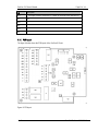
1
Page 1 of 12
SeaCom 210 User's Manual
SeaCom 210 User's Manual
Abstract:
This document is a user manual for the SeaCom 210 Command Group Unit
Revision history
Date
D.Rev.
S.Rev.
Init.
Comment
2004-08-20
01.00
-
CJJ
Document created...
2005-01-10
01.01
CJJ
Ringing hold DIP added
2006-05-19
01.02
LAF
Minor updates to context & rename of document
SeaCom
Rev. 01.02 Date: 2006-05-19
SeaCom 210 User's Manual
Page 2 of 12
SeaCom 210 User's Manual
SeaCom
Rev. 01.02 Date: 2006-05-19
SeaCom 210 User's Manual
Page 3 of 12
Contents
SeaCom 210 general description ..................................................................................... 4
1.
Technical specification................................................................................................. 5
1.1
Installation ....................................................................................................................... 6
2.
Installation principals.................................................................................................... 6
2.1
2.2
Electrical connection.................................................................................................... 7
2.2.1
PCB layout ......................................................................................................... 8
2.2.2
Grounding and shielding considerations............................................................... 9
2.2.3
Cable length considerations ................................................................................ 9
2.3
Volume adjustments ................................................................................................ 10
2.4
Jumper settings......................................................................................................... 10
2.5
Programming the SeaCom 2000 for command group units ........................................ 11
Using the SeaCom 210 .................................................................................................. 12
3.
3.1
Making calls .............................................................................................................. 12
3.2
Receiving calls........................................................................................................... 12
3.3
Conducting calls ........................................................................................................ 12
3.4
Receiving paging calls ............................................................................................... 12
3.5
Command group conference...................................................................................... 12
SeaCom
Rev. 01.02 Date: 2006-05-19
Page 4 of 12
SeaCom 210 User's Manual
1. SeaCom 210 general description
The SeaCom 210 is an industrial environment communication station to be used in engine room,
steering gear room, truster room, lifeboat stations etc. where noisy wet or dirty environment
requires a mechanical robust and simple to use communication station.
The SeaCom 210 connects a loudhailer, which is used both as speaker and as microphone, or
communication can be carried out using a headset with microphone. Optionally a handset can be
connected to the unit. A bell and a rotating light beacon can be connected via normal open relay
outputs. The beacon and the bell are activated during ringing to the unit, and the beacon alone is
activated when the unit receives a paging call.
The SeaCom 210 is controlled by the system via the analogue extension unit and is powered by
24V DC.
The figure 1 below shows a picture and the mechanical outline of the SeaCom 210, and figure 2
shows a full featured communication station using the SeaCom 210.
Figure 1 SeaCom 210 in picture and mechanical dimensions
Beacon
Bell
Headset
SeaCom 210
Loudhailer
Figure 2 A full featured communication station can be build using the SeaCom 210 as the principal
part.
SeaCom
Rev. 01.02 Date: 2006-05-19
SeaCom 210 User's Manual
Page 5 of 12
1.1 Technical specification
•
•
•
•
•
•
•
•
•
•
•
•
•
Output power 10W
Loudhailer impedance 4 or 8 ohms
Supply voltage 18-36V
Standby 280 mW
Operating max. 20W
Bell relay contacts 250V AC 1A
Rotary light relay contacts 250V AC 1A
Temperature -25 to 55C
Size 110x190x90mm
Weight 600g
Compass safe distance > 3m
Environment Exposed
Encapsulation IP66
SeaCom
Rev. 01.02 Date: 2006-05-19
Page 6 of 12
SeaCom 210 User's Manual
2. Installation
The SeaCom 210 is installed on the bulkhead by 4 screws located below the top cover.
Wiring to the unit is taken via cable glands in the bottom of the cabinet where holes are easily can
be drilled to suit the cable dimensions and the mounting actually used.
2.1 Installation principals
The figure 3 below shows a typical system installation including command group units, telephone
sets and PA speakers.
SeaCom2000
Cabins and offices
SeaCom 110
24V DC
SeaCom 110
SeaCom 120
Public area
speakers
SeaCom 210
communication
station
B
B
B
B
H
H
L
L
SeaCom 210
communication
stations
Figure 3. Typical system installation including SeaCom 210 command group units.
The red lines are 24V DC power lines. The black lines are extension lines. More than one SeaCom
110 & 120 can be driven by one extension line whereas the SeaCom 210 units must be
connected to its own extension line.
SeaCom
Rev. 01.02 Date: 2006-05-19
SeaCom 210 User's Manual
Page 7 of 12
2.2 Electrical connection
The tables below shows the connections to the SeaCom 210 unit.
J3
Description
LH +
Loudhailer (speaker as well as microphone)
LH -
Loudhailer (speaker as well as microphone)
HSSP +
Headset loudspeakers +
HSSP -
Headset loudspeakers -
HDMIC +
Headset microphone +
HDMIC -
Headset microphone -
HDPTT +
Headset PTT button + (must be a dry contact)
HDPTT -
Headset PTT button - (must be a dry contact)
24V -
This is the 24V DC negative supply
24V +
This is the 24V DC positive supply
Lb
Extension line b
La
Extension line a
J4
Description
Bell +
Bell relay contact +
Bell .
Bell relay contact -
Bea +
Rotating light beacon +
Bea -
Rotating light beacon -
J1
Description
HSSP +
Handset loudspeakers +
HSSP -
Handset loudspeakers -
HDMIC +
Handset microphone +
HDMIC -
Handset microphone -
HDPTT +
Handset PTT button + (must be a dry contact)
HDPTT -
Handset PTT button - (must be a dry contact)
SeaCom
Rev. 01.02 Date: 2006-05-19
SeaCom 210 User's Manual
Page 8 of 12
J6
Description
B1 +
+ This input is used to sense the PTT button of the front of the SeaCom210
B1 -
- do
B2 +
B2 B3 +
B3 -
2.2.1 PCB layout
The figure 4 below shows the PCB layout of the SeaCom210 unit.
Figure 4 PCB layout
SeaCom
Rev. 01.02 Date: 2006-05-19
SeaCom 210 User's Manual
Page 9 of 12
2.2.2 Grounding and shielding considerations
The SeaCom210 should be powered from a 24V DC distribution point located at the system main
unit. Although local power feeding is possible, this is not recommended.
It is recommended, that cables from the main unit to the SeaCom210 are shielded.
The shield is connected to ground at the main unit and at the SeaCom210 end the shield is
connected to the protective ground terminal found at the aluminium carrier plate.
2.2.3 Cable length considerations
Voltages below 18V DC will make the power amplifier of the SeaCom 210 turn off. When the
SeaCom 210 is powered from the main unit it is important to avoid voltage drops below 18V at
1A.
A rule of thumb is that the square area of the power wires must be 1mm2 / 100m distance.
SeaCom
Rev. 01.02 Date: 2006-05-19
Page 10 of 12
SeaCom 210 User's Manual
2.3 Volume adjustments
4 gain settings are to be set during installation. Volume adjustment is necessary to adapt to the
noise situation found where the SeaCom210 is installed. High noise levels will typically lead to
increased loudhailer and headset speaker volume together with a reduced microphone gain
setting, whereas mounting the SeaCom210 in a quiet room will lead to reduced speaker volume
setting together with a higher microphone gain level.
The settings for each installation are to be tested in place on installation and delivery.
The table below shows the adjustments available
VR
Description
VR1
Loudhailer speaker volume
VR2
Loudhailer microphone sensitivity
VR3
Headset microphone sensitivity
VR4
Headset earcup speakers volume
2.4 Jumper settings
3 jumpers are found out of which only one is currently in use:
Pin
Description
J5,1
When set, full duplex operation is selected for the headset and handset
J5,2
When set, the BELL relay will hold during ringing,
When not set, the BELL relay will close following the ringing signal
J5,3
SeaCom
Rev. 01.02 Date: 2006-05-19
Page 11 of 12
SeaCom 210 User's Manual
2.5 Programming the SeaCom 2000 for command group units
When configuring the maim unit using the Windows base configuration tool, the equipment type
must be selected in the extension board set up form to be a SeaCom 210 Command Group Unit.
Refer to the configuration manual for the main unit e.g. ‘SeaCom2000 Configuration Manual’
When programming the SeaCom210 set up, the telephone number to call when the PTT button on
the front is pressed must be set. If more PTT buttons are used, if a headset or a handset is used,
a number for each PTT must be set. In most applications the same number is used and typically
this will be the bridge telephone number or a ringing group calling more than one extension.
A semi duplex conference group needs to defined to be able to call one ore more SeaCom210
units. As the SeaCom210 is a half duplex unit, only speech in one direction at a time, some
control mechanism is needed. More SeaCom210 units may be defined as a part of the same
group.
SeaCom
Rev. 01.02 Date: 2006-05-19
SeaCom 210 User's Manual
Page 12 of 12
3. Using the SeaCom 210
Using the SeaCOm210 Command Group Unit is straightforward, and will be described in the
following
3.1 Making calls
Press the PTT button of the SeaCom210, the headset or the handset. This will cause the
SeaCom210 to call the programmed telephone number (typically the bridge).
The calling tone will be heard. When the call is answered, the answer will be heard in the loudhailer
and headset and handset.
If the call is not answered, press the PTT button again, and the call will be terminated.
3.2 Receiving calls
When anyone calls the SeaCom210 station, the loudhailer will sound the ringing tone, the rotating
light beacon relay will be activated, and the bell relay will be activated according to the type of
ringing signal received. The ringing tone will be heard in the headset and handset too.
Answering the call is done by pressing the PTT button of the SeaCom210 then speaking into the
loudhailer, which is then used as microphone, or by pressing the PTT button of the headset or
handset then speaking into the microphone of the headset or handset.
3.3 Conducting calls
The SeaCom210 can be used in 3 modes. Mode is selected by the PTT switches. When the
Call/Speak (PTT) button of the front of the SeaCom210 is pressed the ‘loudhailer mode’ is
entered. When the PTT button of the headset is pressed the ‘Headset mode’ is entered, and when
the PTT button of the handset is pressed, ‘Handset mode’ is entered.
In loudhailer mode the loudhailer is used as speaker and when PTT button is pressed, as a
microphone. In Loudhailer mode the microphones of the headset and handset are disabled.
If the PTT button of the headset is pressed, headset mode is entered. In this mode the
microphone of the headset is turned on whenever the PTT button of the headset in held activated.
At any time, pressing the Call/Speak button on the front of the SeaCom210, will return it to
loudhailer mode. During conversation, the headset and handset speakers are always enabled.
3.4 Receiving paging calls
Public address calls are received by the SeaCom210. The loudhailer and the headset and handset
speakers will be activated. The rotating light beacon relay is activated during the paging call. No
user action has to be taken.
3.5 Command group conference
The SeaCom210 is to be used in a command group semi duplex conference. A command group
conference call is a call typically initiated from the bridge telephone. Up till 10 members can be
included in the conference. Initially the speaking part is the bridge telephone, sending an order to
a number of SeaCom210 units. All units are listening to the current speaker. If any of the
participants have something to report back, they will press one of the PTT buttons at their station.
This will turn their station into the speaking part of the conference. All other stations will listen to
the speaking part. The bridge telephone can regain the right to speak by pressing the PTT of the
phone (R button). Refer to the ‘SeaCom2000 Configuration Manual’ for information on how to
configure and set up a semi duplex conference call.
SeaCom
Rev. 01.02 Date: 2006-05-19