1
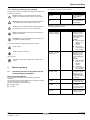
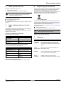
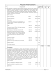
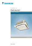
USER MANUAL
Fan coil units
FWC06B7TV1B
FWC07B7TV1B
FWC08B7TV1B
FWC09B7TV1B
FWC06B7FV1B
FWC07B7FV1B
FWC08B7FV1B
FWC09B7FV1B
Cover
Cover
Type numbers
Introduction
Table of contents
1.2.
leofcn
ab
tsT
You have purchased the FWC model fan coil unit. The model
identification code means:
1
Introduction
FW
C
1
FW
Water fan coil unit
1
C
Subclass:
Cassette
C: 3x3
2
06
Total cooling capacity (kW)
2.1. Check that you have all equipment and
the corresponding documentation
2
B
Major model change
7
Minor model change
2.2. Read the safety precautions
3
T
Coil type:
T: 2-pipe
F: 4-pipe
V1
1 phase / 50 Hz / 220-240 V
B
Produced in Europe
1.1. About fan coil units
1
1.2. About your fan coil unit
1.3. About this document
1.3.1. Meaning of warnings and
symbols
2
3
4
5
6
7
1
About your fan coil unit
Before operating
2
Tips for optimal operation
Clean your fan coil unit
Solve problems with your fan coil unit
Dispose of your fan coil unit
Glossary
3
4
4
4
4
Annex: Handover of the installation to
the user
5
06
B
7
T
V1
B
The following models are available:
■
FWC06-07-08-09B7TV1B
2-pipe fan coil units have a single-circuit heat exchanger. The
device can be used for either cooling or heating.
■
FWC06-07-08-09B7FV1B
4-pipe fan coil units have a double-circuit heat exchanger. The
units can be connected to both cooling and heating systems. Use
this type if you have a separate source for cooling and for
heating.
Introduction
Introduction
1
Introduction
Thank you for purchasing this DAIKIN fan coil unit.
Introduction
1.1.
About fan coil units
A fan coil unit provides heating and/or cooling to individual spaces. It
creates a comfortable environment in both commercial and residential
applications. Fan coil units are widely used for the air conditioning of
offices, hotels and houses.
The main components of fan coil units are:
■
a fan,
■
a heat exchanger.
The heat exchanger receives hot or cold water from a heating or
cooling source.
DAIKIN offers a wide range of fan coil units for both concealed and
exposed applications. Contact your installer for a list of related
products.
1.3.
About this document
This document is a user manual. It is written for the person who owns
or operates this fan coil unit. It provides information on:
■
the product itself (“Introduction” on page 1),
■
what you should do before you operating the fan coil unit (“Before
operating” on page 2),
■
what you should do for optimal operation of your fan coil unit
(“Tips for optimal operation” on page 3),
■
how you should clean your fan coil unit (“Clean your fan coil
unit” on page 4),
■
what you should do when there is a problem with your fan coil unit
(“Solve problems with your fan coil unit” on page 4),
■
how you should dispose of your fan coil unit (“Dispose of your fan
coil unit” on page 4),
■
terms that have been used in this user manual that may need
clarification (“Glossary” on page 4).
Introduction
Important
This user manual does not explain how to operate your fan
coil unit. You can only operate your fan coil unit by means
of a controller. Therefore, the operating instructions are
included in the controller box.
Keep this user manual close to hand. It may come in handy later.
The original documentation is written in English. All other languages
are translations of the original documentation.
Introduction
User manual
1
FWC
Fan coil units
4PW65029-1A – 05.2011
Before operating
1.3.1. Meaning of warnings and symbols
Warnings in this manual are classified according to their severity and
probability of happening.
Danger: Indicates an imminently hazardous situation
which, if not avoided, will result in death or serious injury.
Warning: Indicates a potentially hazardous situation which,
if not avoided, could result in death or serious injury.
Caution: Indicates a potentially hazardous situation which,
if not avoided, may result in minor or moderate injury.
An overview of the types that are available:
Decoration panel
Description
Decoration panel standard
BYCQ140CW1
Decoration panel for
the fan coil unit with
normal sealing
colour.
Decoration panel white
BYCQ140CW1W
Decoration panel for
the fan coil unit with
white sealings.
Mandatory equipment: Each fan coil unit must be connected to at
least one of the listed controllers.
Controllers
Notice: Indicates situations that may result in damage to
equipment or property.
Identification code
Identification code
Electronic remote
BRC7F532F
controller - wireless
(cooling and heating)
Information: This symbol identifies useful information, but
no hazardous situation warnings.
Description
Wireless remote
controller to control
each fan coil unit
independently with
cooling and heating
functionality.
Remark:
■
Refer to the VRV
system in the
operation
manual.
■
The function
“auto fan speed”
is not available.
Some types of danger are represented by special symbols:
Electric current
Danger of burning or scalding
Electronic remote
controller - wireless
(cooling only)
BRC7F533F
Other symbols:
This part of the manual is intended for the installer of this
product.
Wireless remote
controller to control
each fan coil unit
independently with
cooling functionality
only.
Remark:
■
Refer to the VRV
system in the
operation
manual.
■
The function
“auto fan speed”
is not available.
Before operating
2
Before operating
Before operating
2.1.
Check that you have all equipment and the
corresponding documentation
Electronic remote
controller - wired
BRC315D7
Wired remote
controller to control
each fan coil unit
independently with
cooling and heating
functionality.
Central remote
controller
DCS302CA51
Remote controller for
centralized control of
all connected units.
Intelligent touch
controller
DCS601C51C
Advanced remote
controller for
centralized control of
all connected units.
Unified ON/OFF
controller
DCS301BA51
Remote controller to
switch all connected
units ON or OFF.
Extra required equipment
The fan coil unit must be used in combination with additional
equipment.
This equipment must be bought separately and is required to operate
the fan coil unit safely and comfortably.
Overview of additional equipment required:
■
decoration panel,
■
controller.
FWC
Fan coil units
4PW65029-1A – 05.2011
User manual
2
Before operating
Extra optional equipment
2.2.
Optionally, you can buy additional equipment for your fan coil unit to
extend the life of your product, increase the level of automation and
improve its ease of use.
Overview of the optional additional equipment for your fan coil unit:
An overview of the types that are available:
■
air handling options,
■
sensor,
■
timer,
■
valves,
■
electronic circuits (PCB).
Air handling
options
Sealing member of
air discharge outlet
Identification code
KDBHQ55C140
Description
Blocking parts to
close one or more air
outlets of the fan coil
unit.
Long-life
replacement filter
KAFP551K160
High quality filter.
Fresh air intake kit
KDDQ55C140
Kit which can be
connected to the
ventilation system in
order to supply fresh
air to the fan coil unit.
Sensor
Remote temperature
sensor
Identification code
KRCS01-4
Description
Replacement sensor
to measure
temperature remotely
from a location other
than that in which the
controller is installed.
Read the safety precautions
Your fan coil unit is built to meet all recognized technical requirements.
Operate your fan coil unit according to the instructions in the included
documentation and the manuals of the additional equipment (e.g.
controller). Any other usage is considered as improper and may result
in property damage, serious physical injuries or death. Resulting
damage caused by improper use is the sole responsibility of the user
and the user alone.
To prevent any risk:
■
carefully read the safety precautions,
■
operate your fan coil unit according to the documentation.
Precautions for installation
The installer should install and connect your fan coil unit as described
in the installation manual. Please note that the installer can only install
your fan coil unit:
■
in a concealed ceiling,
■
in perfect condition.
Precautions before operating
Only operate your fan coil unit after it has been installed by a licensed
installer. Verify that the installation has been completed by checking
that the “Annex: Handover of the installation to the user” on page 5
has been filled in completely.
Precautions for operating
Only operate a fan coil unit if you are fully alert and aware.
Fan coil units are not intended for use by persons with reduced
physical, sensory or mental capabilities or those who have not used
the fan coil unit before, including children. When these persons want
to use the fan coil unit, the person responsible for their safety must
supervise them or instruct them in the use of the fan coil unit.
Supervise children to ensure that they do not play with the fan coil unit.
If you feel unsure about operating the fan coil unit, contact your
installer for advice and information.
Tips for optimal operation
Timer
Schedule timer
Valves
2-way valve
(ON/OFF type)
3-way valve
(ON/OFF type)
Electronic circuits
Identification code
DST301BA51
Identification code
EKMV2C09B7
EKMV3C09B7
Identification code
Description
Controller with
schedule timing
functionality.
Description
Electronic 2-way
valve to control the
water supply
(+EKRP1C11).
Electronic 3-way
valve to control the
water supply
(+EKRP1C11).
3
■
Adjust the room temperature properly for a comfortable
environment. Avoid excessive heating or cooling. Notice that it
may take some time for the room temperature to reach the set
temperature. Consider using the timer setting options.
■
Prevent direct sunlight from entering a room during cooling
operation by using curtains or blinds.
■
Ventilate the room regularly. Using the unit for long periods of
time requires attentive ventilation of the room.
■
Keep doors and windows closed when the unit is in operation. If
the doors and windows remain open, air will flow out and
decrease the effect of cooling and heating.
■
Never place objects near the air inlet and the air outlet of the unit.
It may reduce the effectiveness or cause the unit to stop.
■
Turn off the main power supply switch when not using the fan coil
unit for long periods of time. Electricity is consumed so long as
the switch is on. Turn off the main power supply switch in order to
save energy.
■
Fully use the function of air flow direction adjustment if available.
As cold air gathers on the floor and warm air gathers against the
ceiling, it is recommended to set the air flow direction during
cooling operation parallel to the ceiling and to set it downwards
during heating operation. Be sure that you do not direct air flow
on to the inhabitants of the room.
Description
Valve control PCB
EKRP1C11
Mandatory electronic
circuit when 2-way or
3-way valve is used.
Optional PCB for
Modbus connection
EKFCMBCB7
Electronic circuit with
Modbus interface
connections.
Tips for optimal operation
Clean your fan coil unit
Wiring adaptor for
KRP4A(A)53
electrical appendices KRP2A52
Electronic circuit with
additional
connections for
external input/output
signals.
Before operating
User manual
3
FWC
Fan coil units
4PW65029-1A – 05.2011
Clean your fan coil unit
4
Clean your fan coil unit
Clean your fan coil unit
To clean the outside of your fan coil unit:
1
Switch off the fan coil unit.
2
Clean the outside of the fan coil unit with a soft cloth.
Notice
Do not pour any liquid on the fan coil unit. This could
damage the components inside it.
6
Dispose of your fan coil unit
Your fan coil unit was designed to be environment friendly. DAIKIN has
complied with the standards for environmentally-friendly disposal.
This means that you have to dispose of your fan coil unit in
accordance with the applicable legislation. By ensuring this product is
disposed of correctly, you help to prevent potential negative
consequences for the environment and human health.
Never clean your fan coil unit with:
■
any aggressive chemical solvent,
■ water hotter than 50°C.
For maintenance of your fan coil unit, contact your installer or service
company.
Solve problems with your fan coil unit
5
Solve problems with your fan coil
unit
When your fan coil unit does not function well, you can try to solve any
problem with the corrective actions in this chapter.
If the problem persists or is not addressed in this chapter, contact your
installer or service company.
Fig. 6.1: WEEE symbol
Your fan coil unit is categorized as an electrical and electronic product.
It is marked with the symbol illustrated in figure “WEEE symbol” on
page 4. This symbol means that your fan coil unit should be recycled
and not disposed of in unsorted municipal waste.
To dispose of your fan coil unit, contact your installer. The installer and
qualified instances will:
■
dismantle the fan coil unit,
■
re-use, recycle and recover parts of the fan coil unit.
Warning
Never dismantle the fan coil unit yourself.
Your fan coil unit does not function
If your fan coil unit does not function:
DAIKIN and the environment thank you!
Glossary
Check:
If yes,
Has the fan coil unit been
switched OFF?
Switch the fan coil unit ON.
Is there a power failure?
Restore the power supply.
Has the circuit breaker (fuse)
been tripped?
Contact your installer or service
company.
7
Glossary
Term
Applicable
legislation:
Your fan coil unit does not cool or heat well
If your fan coil unit does not cool or heat well:
Check:
If yes,
Is there an obstacle near the air
inlet or air outlet?
Remove the obstacle.
Are any doors and windows
open?
Close doors and windows.
Contact your installer or service
company.
Your fan coil unit leaks water
All international, European, national and local
directives, laws, regulations and/or codes which
are relevant and applicable for a certain product or
domain
Circuit
Safety device used in electrical installations to
breaker (fuse): prevent electric shock
Installer:
Technical skilled person who is qualified to install
fan coil units and other DAIKIN products
Service
company:
Qualified company which can perform or
coordinate the required service to the fan coil unit
Is the fan coil unit running at low Select medium speed or high
speed?
speed.
Are the air filters dirty?
Meaning
Annex: Handover of the installation to the user
Shut down the unit and contact your installer or service company.
Dispose of your fan coil unit
FWC
Fan coil units
4PW65029-1A – 05.2011
User manual
4
Annex: Handover of the installation to the user
Annex: Handover of the installation to the
user
Tick
Ensure that the user has a printed version of the user
manual and the installation manual and ask him/her to
keep it for future reference.
To be filled in by the installer once the test run is finished and the fan
coil unit(s) operate(s) properly.
Tick
when checked
Explain the user how to properly operate the system, and
what he/she has to do in case of problems.
Explain to the user what system is installed on site.
Complete the ID cards below for each installed fan coil unit.
This information may be useful for the user in future
servicing. Fill in the place of installation (room), the model
name (see nameplate of the fan coil unit) and list the
optional equipment which is installed.
Fan coil unit 1
Place of
installation:
Place of
installation:
Model name:
Model name:
Optional equipment:
Optional equipment:
Fan coil unit 3
Place of
installation:
Model name:
Model name:
Optional equipment:
Optional equipment:
Place of
installation:
Model name:
Model name:
Optional equipment:
Optional equipment:
p
Your DAIKIN product was installed by:
Fan coil unit 8
Place of
installation:
Place of
installation:
Model name:
Model name:
Optional equipment:
Optional equipment:
User manual
Date:
Signature:
Fan coil unit 6
Place of
installation:
Fan coil unit 7
Show the user what maintenance jobs he/she has to do in
relation to cleaning the unit.
Fan coil unit 4
Place of
installation:
Fan coil unit 5
5
Fan coil unit 2
when checked
FWC
Fan coil units
4PW65029-1A – 05.2011
Cover Rear
Copyright 2010 Daikin
Cover Rear
4PW65029-1A 05.2011