1
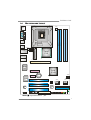
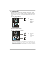
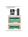
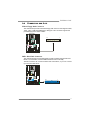
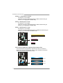
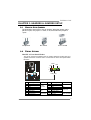
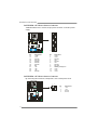
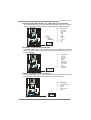
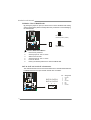
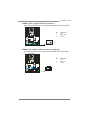
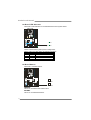
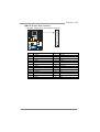
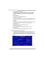
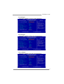
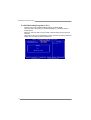
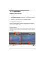
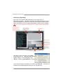
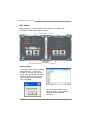
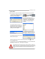
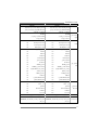
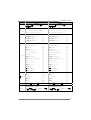
TP35D2-A7 SE Setup Manual FCC Information and Copyright This equipment has been tested and found to comply with the limits of a Class B digital device, pursuant to Part 15 of the FCC Rules. These limits are designed to provide reasonable protection against harmful interference in a residential installation. This equipment generates, uses, and can radiate radio frequency energy and, if not installed and used in accordance with the instructions, may cause harmful interference to radio communications. There is no guarantee that interference will not occur in a particular installation. The vendor makes no representations or warranties with respect to the contents here and specially disclaims any implied warranties of merchantability or fitness for any purpose. Further the vendor reserves the right to revise this publication and to make changes to the contents here without obligation to notify any party beforehand. Duplication of this publication, in part or in whole, is not allowed without first obtaining the vendor’s approval in writing. The content of this user’s manual is subject to be changed without notice and we will not be responsible for any mistakes found in this user’s manual. All the brand and product names are trademarks of their respective companies. Table of Contents Chapter 1: Introduction ............................................................ 1 1.1 Before You Start......................................................................................... 1 1.2 Package Checklist ..................................................................................... 1 1.3 Motherboard Features.............................................................................. 2 1.4 Rear Panel Connectors (for Ver 5.x)....................................................... 4 1.5 Rear Panel Connectors (for Ver 6.x)....................................................... 4 1.6 Motherboard Layout................................................................................. 5 Chapter 2: Hardware Installation ............................................. 6 2.1 Installing Central Processing Unit (CPU) ............................................... 6 2.2 FAN Headers.............................................................................................. 8 2.3 Installing System Memory ........................................................................ 9 2.4 Connectors and Slots................................................................................ 11 Chapter 3: Headers & Jumpers Setup ..................................... 13 3.1 How to Setup Jumpers............................................................................. 13 3.2 Detail Settings .......................................................................................... 13 Chapter 4: T-Series BIOS & Software ..................................... 20 4.1 T-Series BIOS............................................................................................. 20 4.2 T-Series Software...................................................................................... 29 Chapter 5: Useful Help ............................................................ 34 5.1 Driver Installation Note.......................................................................... 34 5.2 Award BIOS Beep Code .......................................................................... 35 5.3 Extra Information.................................................................................... 35 5.4 Troubleshooting ....................................................................................... 36 Appendencies: SPEC In Other Language ................................ 38 German.................................................................................................................. 38 France .................................................................................................................... 40 Italian..................................................................................................................... 42 Spanish ................................................................................................................... 44 Portuguese ............................................................................................................ 46 Polish...................................................................................................................... 48 Russian ................................................................................................................... 50 Arabic..................................................................................................................... 52 Japanese ................................................................................................................ 54 TP35D2-A7 SE CHAPTER 1: INTRODUCTION 1.1 BEFORE YOU START Thank you for choosing our product. Before you start installing the motherboard, please make sure you follow the instructions below: 1.2 Prepare a dry and stable working environment with sufficient lighting. Always disconnect the computer from power outlet before operation. Before you take the motherboard out from anti-static bag, ground yourself properly by touching any safely grounded appliance, or use grounded wrist strap to remove the static charge. Avoid touching the components on motherboard or the rear side of the board unless necessary. Hold the board on the edge, do not try to bend or flex the board. Do not leave any unfastened small parts inside the case after installation. Loose parts will cause short circuits which may damage the equipment. Keep the computer from dangerous area, such as heat source, humid air and water. PACKAGE CHECKLIST HDD Cable X 1 Serial ATA Cable X 2 Rear I/O Panel for ATX Case X 1 User’s Manual X 1 Fully Setup Driver CD X 1 FDD Cable X 1 (optional) USB 2.0 Cable X1 (optional) S/PDIF out Cable X 1 (optional) Serial ATA Power Cable X 1 (optional) Note: The package contents may differ by area or your motherboard version. 1 Motherboard Manual 1.3 MOTHERBOARD FEATURES Ver 5.x CPU FSB Chipset Ver 6.x LGA 775 LGA 775 Intel Core2Duo / Core2Quad / Celeron 4xx / Intel Core2Duo / Core2Quad / Celeron 4xx / Pentium D / Pentium 4 / Celeron D processor Pentium D / Pentium 4 / Celeron D processor Supports Hyper-Threading / Execute Disable Bit / Supports Hyper-Threading / Execute Disable Bit / Enhanced Intel SpeedStep® / Intel Enhanced Intel SpeedStep® / Intel Architecture-64 / Extended Memory 64 Architecture-64 / Extended Memory 64 Technology / Virtualization Technology Technology / Virtualization Technology Support 533 / 800 / 1066 / 1333 MHz Support 533 / 800 / 1066 / 1333 MHz Support 1600 MHz (with DDR2 800) Support 1600 MHz (with DDR2 800) Intel P35 Intel P35 Intel ICH9 Intel ICH9 ITE 8718F ITE 8718F Provides the most commonly used legacy Super Provides the most commonly used legacy Super Super I/O Main Memory IDE SATA 2 2 I/O functionality. I/O functionality. Low Pin Count Interface Low Pin Count Interface Environment Control initiatives, Environment Control initiatives, Hardware Monitor Controller Hardware Monitor Controller Fan Speed Controller Fan Speed Controller ITE's "Smart Guardian" function ITE's "Smart Guardian" function DIMM Slots x 4 DIMM Slots x 4 Each DIMM supports 256MB / 512MB / 1GB / Each DIMM supports 256MB / 512MB / 1GB / 2GB DDR2 2GB DDR2 Max Memory Capicity 8GB Max Memory Capicity 8GB Dual Channel Mode DDR2 memory module Dual Channel Mode DDR2 memory module Supports DDR2 800 / 667 Supports DDR2 800 / 667 Supports DDR2 533 (with FSB 533/1066 CPU) Supports DDR2 533 (with FSB 533/1066 CPU) Registered DIMM and ECC DIMM is not Registered DIMM and ECC DIMM is not supported supported JMicro JMB368 JMicro JMB368 Ultra DMA 33 / 66 / 100 / 133 Bus Master Mode Ultra DMA 33 / 66 / 100 / 133 Bus Master Mode supports PIO Mode 0~4 supports PIO Mode 0~4 Integrated Serial ATA Controller Integrated Serial ATA Controller Data transfer rates up to 3.0 Gb/s. Data transfer rates up to 3.0 Gb/s. SATA Version 2.0 specification compliant SATA Version 2.0 specification compliant TP35D2-A7 SE Ver 5.x Ver 6.x Realtek RTL 8110SC / 8100C (optional) LAN Sound Codec Slots On Board Connector Realtek RTL 8110SC / 8100C (optional) 10 / 100 Mb/s / 1Gb/s auto negotiation (Gigabit 10 / 100 Mb/s / 1Gb/s auto negotiation (Gigabit bandwidth is for RTL 8110SC only) bandwidth is for RTL 8110SC only) Half / Full duplex capability Half / Full duplex capability ALC888 ALC662 7.1 channels audio out 5.1 channels audio out High Definition Audio High Definition Audio PCI slot x3 PCI slot x3 PCI Express x 16 slot x1 PCI Express x 16 slot x1 PCI Express x 4 slot x1 PCI Express x 4 slot x1 PCI Express x 1 slot x1 PCI Express x 1 slot x1 Floppy connector x1 Floppy connector x1 Printer Port Connector x1 Printer Port Connector x1 IDE Connector x1 IDE Connector x1 SATA Connector x4 SATA Connector x4 Front Panel Connector x1 Front Panel Connector x1 Front Audio Connector x1 Front Audio Connector x1 CD-in Connector x1 CD-in Connector x1 S/PDIF out connector x1 S/PDIF out connector x1 S/PDIF in connector(optional) x1 S/PDIF in connector(optional) x1 CPU Fan header x1 CPU Fan header x1 System Fan header x2 System Fan header x2 Clear CMOS header x1 Clear CMOS header x1 USB connector x3 USB connector x3 Power Connector (24pin) x1 Power Connector (24pin) x1 Power Connector (4pin) x1 Power Connector (4pin) x1 PS/2 Keyboard x1 PS/2 Keyboard x1 x1 PS/2 Mouse x1 Back Panel Serial Port x1 Serial Port x1 I/O LAN port x1 LAN port x1 USB Port x6 USB Port x6 Audio Jack x6 Audio Jack x3 PS/2 Mouse Board Size 220 (W) x 305 (L) mm 220 (W) x 305 (L) mm Windows 2000 / XP / VISTA Windows 2000 / XP / VISTA OS Support Biostar Reserves the right to add or remove support for any OS with or without notice Biostar Reserves the right to add or remove support for any OS with or without notice 3 Motherboard Manual 1.4 REAR PANEL CONNECTORS (FOR VER 5.X) PS/2 Mouse PS/ 2 Keyboard LAN COM1 USBX2 USBX2 Center 1.5 Audio Jack USBX2 Line In Rear Line Out Side Mic In REAR PANEL CONNECTORS (FOR VER 6.X) PS/2 Mouse LAN Line In/ Surround Line Out Mic I n 1/ Bass/ Center PS/ 2 Keyboard 4 COM1 USBX2 USBX2 USBX2 TP35D2-A7 SE 1.6 MOTHERBOARD LAYOUT JCFAN1 JKBMS1 LGA775 JPRNT1 JCOM1 CPU1 DDR2_B2 DDR2_B1 JUSB1 DDR2_A2 DDR2_A1 JUSB2 JNFAN1 JRJ45USB1 JATXPWR1 Intel P35 JAUDIO1 (for Ver 5.x) JAUDIO2 (for Ver 6.x) JATXPWR2 PEX16_1 Super I/O Intel ICH9 PEX4_1 BAT1 PEX1_1 JCMOS1 LAN JSFAN1 PCI1 SATA3 SATA1 SATA4 SATA2 BIOS PCI2 IDE CODEC IDE1 PCI3 LED2 RSTSW2 JSPDIF_OUT1 LED1 FDD1 JAUDIOF1 JCDIN1 JSPDIF_IN1(optional) JUSB5 JUSB4 JUSB3 J PANEL1 PWRSW1 Note: ■ represents the 1st pin. 5 Motherboard Manual CHAPTER 2: HARDWARE INSTALLATION 2.1 INSTALLING CENTRAL PROCESSING UNIT (CPU) Special Notice: Remove Pin Cap before installation, and make good preservation for future use. When the CPU is removed, cover the Pin Cap on the empty socket to ensure pin legs won’t be damaged. Pin Cap Step 1: Pull the socket locking lever out from the socket and then raise the lever up to a 90-degree angle. 6 TP35D2-A7 SE Step 2: Look for the triangular cut edge on socket, and the golden dot on CPU should point forwards this triangular cut edge. The CPU will fit only in the correct orientation. Step 2-1: Step 2-2: Step 3: Hold the CPU down firmly, and then lower the lever to locked position to complete the installation. Step 4: Put the CPU Fan and heatsink assembly on the CPU and buckle it on the retention frame. Connect the CPU FAN power cable into the JCFAN1. This completes the installation. 7 Motherboard Manual 2.2 FAN HEADERS These fan headers support cooling-fans built in the computer. The fan cable and connector may be different according to the fan manufacturer. Connect the fan cable to the connector while matching the black wire to pin#1. JCFAN1: CPU Fan Header 4 Pin 1 2 3 1 4 Assignment Ground +12V FAN RPM rate sense Smart Fan Control JSFAN1: System Fan Header JNFAN1: Northbridge Fan Header 1 3 Pin JNFAN1 1 2 3 Assignment Ground +12V FAN RPM rate sense 1 3 JSFAN1 Note: The JNFAN1/JSFAN1 support 3-pin head connectors, and the JCFAN1 supports 4-pin head connector. When connecting with wires onto connectors, please note that the red wire is the positive and should be connected to pin#2, and the black wire is Ground and should be connected to GND. 8 TP35D2-A7 SE 2.3 INSTALLING SYSTEM MEMORY DDR2_B1 DDR2_B2 DDR2_A1 DDR2_A2 A. Memory Modules 1. Unlock a DIMM slot by pressing the retaining clips outward. Align a DIMM on the slot such that the notch on the DIMM matches the break on the Slot. 2. Insert the DIMM vertically and firmly into the slot until the retaining chip snap back in place and the DIMM is properly seated. 9 Motherboard Manual B. Memory Capacity DIMM Socket Location DDR Module DDR2_A1 256MB/512MB/1GB/2GB DDR2_A2 256MB/512MB/1GB/2GB DDR2_B1 256MB/512MB/1GB/2GB DDR2_B2 256MB/512MB/1GB/2GB Total Memory Size Max is 8GB. C. Dual Channel Memory installation To trigger the Dual Channel function of the motherboard, the memory module must meet the following requirements: Install memory module of the same density in pairs, shown in the following table. Dual Channel Status DDR2_A1 DDR2_A2 DDR2_B1 DDR2_B2 Enabled O X O X Enabled X O X O Enabled O O O O (O means memory installed, X means memory not installed.) The DRAM bus width of the memory module must be the same (x8 or x16) 10 TP35D2-A7 SE 2.4 CONNECTORS AND SLOTS FDD1: Floppy Disk Connector The motherboard provides a standard floppy disk connector that supports 360K, 720K, 1.2M, 1.44M and 2.88M floppy disk types. This connector supports the provided floppy drive ribbon cables. 33 1 34 2 IDE1: Hard Disk Connector The motherboard has a 32-bit Enhanced PCI IDE Controller that provides PIO Mode 0~4, Bus Master, and Ultra DMA 33/66/100/133 functionality. The IDE connector can connect a master and a slave drive, so you can connect up to two hard disk drives. 39 1 40 2 11 Motherboard Manual PEX16_1: PCI-Express x16 Slot - PCI-Express 1.0a compliant. Maximum theoretical realized bandwidth of 4GB/s simultaneously per direction, for an aggregate of 8GB/s totally. PEX4_1: PCI-Express x4 Slot - PCI-Express 1.0a compliant. Maximum theoretical realized bandwidth of 1GB/s simultaneously per direction, for an aggregate of 2GB/s totally. PEX1_1: PCI-Express x1 Slot - PCI-Express 1.0a compliant. Maximum theoretical realized bandwidth of 250MB/s simultaneously per direction, for an aggregate of 500MB/s totally. PEX16_1 PEX4_1 PEX1_1 PCI1~PCI3: Peripheral Component Interconnect Slots This motherboard is equipped with 3 standard PCI slots. PCI stands for Peripheral Component Interconnect, and it is a bus standard for expansion cards. This PCI slot is designated as 32 bits. PCI1 PCI2 PCI3 12 TP35D2-A7 SE CHAPTER 3: HEADERS & JUMPERS SETUP 3.1 HOW TO SETUP JUMPERS The illustration shows how to set up jumpers. When the jumper cap is placed on pins, the jumper is “close”, if not, that means the jumper is “open”. Pin opened 3.2 Pin closed Pin1-2 closed DETAIL SETTINGS JPANEL1: Front Panel Header This 16-pin connector includes Power-on, Reset, HDD LED, Power LED, and speaker connection. It allows user to connect the PC case’s front panel switch functions. HLED SPK RST + ++ - 8 16 1 9 On/Off PWR_LED Pin 1 2 3 4 5 6 7 8 Assignment +5V N/A N/A Speaker HDD LED (+) HDD LED (-) Ground Reset control Function Speaker Connector Hard drive LED Reset button Pin 9 10 11 12 13 14 15 16 Assignment N/A N/A N/A Power LED (+) Power LED (+) Power LED (-) Power button Ground Function N/A N/A Power LED Power-on button 13 Motherboard Manual JATXPWR2: ATX Power Source Connector JATXPW2 allows user to connect 24-pin power connector on the ATX power supply. 13 1 24 12 Pin Assignment Pin Assignment 13 14 15 16 17 18 19 20 21 22 23 24 +3.3V -12V Ground PS_ON Ground Ground Ground NC +5V +5V +5V Ground 1 2 3 4 5 6 7 8 9 10 11 12 +3.3V +3.3V Ground +5V Ground +5V Ground PW_OK Standby Voltage+5V +12V +12V +3.3V JATXPWR1: ATX Power Source Connector By connecting this connector, it will provide +12V to CPU power circuit. 1 2 14 4 3 Pin 1 2 3 4 Assignment +12V +12V Ground Ground TP35D2-A7 SE JUSB3/JUSB4/JUSB5: Headers for USB 2.0 Ports at Front Panel This header allows user to connect additional USB cable on the PC front panel, and also can be connected with internal USB devices, like USB card reader. Pin 1 2 3 4 5 6 7 8 9 10 JUSB5 JUSB4 JUSB3 9 1 10 2 Assignment +5V (fused) +5V (fused) USBUSBUSB+ USB+ Ground Ground Key NC JAUDIOF1: Front Panel Audio Header This header allows user to connect the front audio output cable with the PC front panel. This header allows only HD audio front panel connector; AC’97 connector is not acceptable. 9 1 10 2 Pin 1 2 3 4 5 6 7 8 9 10 Assignment Mic Left in Ground Mic Right in GPIO Right line in Jack Sense Front Sense Key Left line in Jack Sense JCDIN1: CD-ROM Audio-in Connector This connector allows user to connect the audio source from the variaty devices, like CD-ROM, DVD-ROM, PCI sound card, PCI TV turner card etc.. Pin 1 2 3 4 4 Assignment Left Channel Input Ground Ground Right Channel Input 1 15 Motherboard Manual JCMOS1: Clear CMOS Header By placing the jumper on pin2-3, it allows user to restore the BIOS safe setting and the CMOS data, please carefully follow the procedures to avoid damaging the motherboard. 1 3 Pin 1-2 Close: Normal Operation (default). 1 1 3 3 Pin 2-3 Close: Clear CMOS data. ※ Clear CMOS Procedures: 1. 2. 3. 4. 5. 6. Remove AC power line. Set the jumper to “Pin 2-3 close”. Wait for five seconds. Set the jumper to “Pin 1-2 close”. Power on the AC. Reset your desired password or clear the CMOS data. SATA1~SATA4: Serial ATA Connectors The motherboard has a PCI to SATA Controller with 4 channels SATA interface, it satisfies the SATA 2.0 spec and with transfer rate of 3.0Gb/s. SATA3 SATA1 SATA4 SATA2 7 16 4 1 Pin 1 2 3 4 5 6 7 Assignment Ground TX+ TXGround RXRX+ Ground TP35D2-A7 SE JSPDIF_OUT1: Digital Audio-out Connector This connector allows user to connect the PCI bracket SPDIF output header. Pin 1 2 3 3 Assignment +5V SPDIF_OUT Ground 1 JSPDIF_IN1: Digital Audio-in Connector (Optional) This connector allows user to connect the PCI bracket SPDIF input header. Pin 1 2 3 3 Assignment +5V SPDIF_IN Ground 1 17 Motherboard Manual On-Board LED Indicators There are 2 LED indicators on the motherboard to show system status. LED2 LED1 LED1 and LED2: These 2 LED indicate system power on diagnostics. Please refer to the table below for different messages: LED1 ON ON OFF OFF LED2 ON OFF ON OFF Message Normal Memory Error VGA Error Abnormal: CPU / Chipset error. On-Board Buttons There are 2 on-board buttons. RSTSW2 PWRSW1 PWRSW1: This is an on-board Power Switch button. RSTSW2: This is an on-board Reset button. 18 TP35D2-A7 SE JPRNT1: Printer Port Connector This header allows you to connect printer on the PC. 25 2 Pin 1 2 3 4 5 6 7 8 9 10 11 12 13 Assignment -Strobe -ALF Data 0 -Error Data 1 -Init Data 2 -Scltin Data 3 Ground Data 4 Ground Data 5 Pin 14 15 16 17 18 19 20 21 22 23 24 25 26 1 Assignment Ground Data 6 Ground Data 7 Ground -ACK Ground Busy Ground PE Ground SCLT Key 19 Motherboard Manual CHAPTER 4: T-SERIES BIOS & SOFTWARE 4.1 T-SERIES BIOS T-Series BIOS Features Overclocking Navigator Engine (O.N.E.) CMOS Reloading Program (C.R.P.) Memory Integration Test (M.I.T., under Overclock Navigator Engine) Integrated Flash Program (I.F.P.) Self Recovery System (S.R.S) Smart Fan Function (under PC Health Status) !! WARNING !! For better system performance, the BIOS firmware is being continuously updated. The BIOS information described below in this manual is for your reference only and the actual BIOS information and settings on board may be different from this manual. For further information of setting up the BIOS, please refer to the BIOS Manual in the Setup CD. NOTE Overclock is an optional process, but not a “must-do” process; it is not recommended for inexperienced users. Therefore, we will not be responsible for any hardware damage which may be caused by overclocking. We also would not guarantee any overclocking performance. 20 TP35D2-A7 SE A. Overclocking Navigator Engine (O.N.E.) ONE provides two powerful overclocking engines: MOS and AOS for both Elite and Casual overclockers. Manual Overclock System (M.O.S.) MOS is designed for experienced overclock users. It allows users to customize personal overclock settings. ↓ 21 Motherboard Manual CPU Clock Ratio & CPU Clock CPU Clock Ratio x CPU Clock = CPU Frequency. CPU Frequency is directly in proportion to system performance. To maintain the system stability, CPU voltage needs to be increased also when raising CPU frequency. PCI-E Clock Select It helps to increase VGA card performance. System Me mory Frequency To get better system performance, sometimes downgrading the memory frequency is necessary when CPU frequency is adjusted over the upper limit. CPU Voltage This function will increase CPU stability when overclocking. However, the CPU temperature will increase when CPU voltage is increased. (G)MCH Voltage This function lets you select the (G)MCH voltage. FSB Termination Voltage This function will increase chipset stability when overclocking. Memory Voltage This function will increase memory stability when overclocking. Automatic Overclock System (A.O.S.) For beginners in overclock field, BET had developed an easy, fast, and powerful feature to increase the system performance, named A.O.S. Based on many tests and experiments, A.O.S. provides 3 ideal overclock configurations that are able to raise the system performance in a single step. 22 TP35D2-A7 SE V6 Tech Engine This engine will make a good over-clock performance. V8 Tech Engine This engine will make a better over-clock performance. V12 Tech Engine This engine will make a best over-clock performance. 23 Motherboard Manual B. CMOS Reloading Program (C.R.P.) It allows users to save different CMOS settings into BIOS-ROM. Users are able to reload any saved CMOS setting for customizing system configurations. Moreover, users are able to save an ideal overclock setting during overclock operation. There are 50 sets of record addresses in total, and users are able to name the CMOS data according to personal preference. 24 TP35D2-A7 SE C. Memory Integration Test (M.I.T.) This function is under “Overclocking Navigator Engine” item. MIT allows users to test memory compatibilities, and no extra devices or software are needed. Step 1 The default setting under this item is “Disabled”; the condition parameter should be changed to “Enable” to proceed this test. ↓ Step 2 Save and Exit from CMOS setup and reboot the system to activate this test. Run this test for 5 minutes (minimum) to ensure the memory stability. Step 3 When the process is done, change the setting back from “Enable” to “Disable” to complete the test. 25 Motherboard Manual D. Self Recovery System (S.R.S.) This function can’t be seen under BIOS setup; and is always on whenever the system starts up. However, it can prevent system hang-up due to inappropriate overclock actions. When the system hangs up, S.R.S. will automatically log in the default BIOS setting, and all overclock settings will be re-configured. E. Integrated Flash Program (I.F.P.) IFP is a safe and quick way to upgrade BIOS. Step 1 Go to the website to download the latest BIOS file. Then, save the file into a floppy disk. Step 2 Insert the floppy disk and reboot the system to get into CMOS screen. Step 3 Select the item “Integrated Flash Program” to get the following frame and choose the BIOS file downloaded in step 1. Step 4 Press “Enter” key to start BIOS file loading, and BIOS updating will process automatically. Step 5 When the BIOS update is completed, press YES to the message “Flash done, Reset system”, and the system will reboot automatically to finish the process. Advise: You can update the system BIOS by simply pressing “Enter” key for three times. 26 TP35D2-A7 SE F. Smart Fan Function Smart Fan Function is under “Smart Fan Option” in “PC Health Status”. This is a brilliant feature to control CPU/System Temperature vs. Fan speed. When enabling Smart Fan function, Fan speed is controlled automatically by CPU/System temperature. This function will protect CPU/System from overheat problem and maintain the system temperature at a safe level. ↓ Smart Fan Calibration Choose this item and then the BIOS will automatically test and detect the CPU/System fan functions and show CPU/System fan speed. PWM Duty Off <℃> If the CPU/System temperature is lower than the set value, the CPU/System fan will turn off. The range is from 0℃~127℃, with an interval of 1℃. 27 Motherboard Manual PWM Duty Start <℃> The CPU/System fan starts to work when CPU/System temperature arrives to this set value. The range is from 0℃~127℃, with an interval of 1℃. Start PWM Value When CPU/System temperature arrives to the set value, the CPU/System fan will work under Smart Fan Function mode. The range is from 0~127, with an interval of 1. Smart Fan Slope Increasing the value of slope PWM will raise the speed of CPU/System fan. The range is from 1~127, with an interval of 1. 28 TP35D2-A7 SE 4.2 T-SERIES SOFTWARE Installing T-Series Software 1. Insert the Setup CD to the optical drive. The drivers installation program would appear if the Autorun function has been enabled. 2. Select Software Installation, and then click on the respective software title. 3. Follow the on-screen instructions to complete the installation. Launching T-Series Software After the installation process, you will see the software icon “HW Monitor”/ “eHOT Line” / “Tseries BIOS Update” appears on the desktop. Double-click the icon to launch T-Series utility. Hardware Monitor HW Monitor is a monitor utility that helps you to maintain the health of the PC. It provides real-time information of CPU/GPU/System temperature, fan speed, and voltage. This area shows volt age information Voltage Panel This area shows CPU inf ormation Turn to Fan Panel This area shows CPU/System t emperat ure Fan Panel This area shows CPU/System f an speed Turn to Voltage P anel 29 Motherboard Manual eHot-Line (Optional) eHot-Line is a convenient utility that helps you to contact with our Tech-Support system. This utility will collect the system information which is useful for analyzing the problem you may have encountered, and then send these information to our tech-support department to help you fix the problem. Before you use this utility, please set Outlook Express as your default e-mail client application program. represent s import ant *information that you must provide. Without this informat ion, you may not be able to send out the mail. This block will show the information which would be collect ed in the mail. condition * Describe of your system. your area or * Select the area close to you. Provide the e-mail address that you would like to send t he copy to. the name of * Provide the memory module manufacturer. Provide the name of the power supply manufacturer and the model no. Send the mail out. Exit this dialog. Save these information to a .txt file After filling up this information, click “Send” to send the mail out. A warning dialog would appear asking for your confirmation; click “Send” to confirm or “Do Not Send” to cancel. If you want to save this information to a .txt file, click “Save As…” and then you will see a saving dialog appears asking you to enter file name. 30 TP35D2-A7 SE Enter the file name and then click “Save”. Your system information will be saved to a .txt file. Open the saved .txt file, you will see your system information including motherboard/BIOS/CPU/video/ device/OS information. This information is also concluded in the sent mail. We will not share customer’s data with any other third parties, so please feel free to provide your system information while using eHot-Line service. If you are not using Outlook Express as your default e-mail client application, you may need to save the system information to a .txt file and send the file to our tech support with other e-mail application. Go to the following web http://www.biostar.com.tw/app/en-us/about/contact.php for getting our contact information. 31 Motherboard Manual BIOS Update BIOS Update is a convenient utility which allows you to update your motherboard BIOS under Windows system. AWARD BIOS Show current BIOS information AMI BIOS Clear CMOS function (Only for AWARD BIOS) Save current BIOS to a .bin file Update BIOS with a BIOS file <Backup BIOS> Once click on this button, the saving dialog will show. Choose the position to save file and enter file name. (We recommend that the file name should be English/number and no longer than 7 characters.) Then click Save. After the saving process, finish dialog will show. Click on OK to complete the BIOS Backup procedure. 32 TP35D2-A7 SE <Update BIOS> Before doing this, please download the proper BIOS file from the website. For AWARD BIOS, update BIOS procedure should be run with Clear CMOS function, so please check on Clear CMOS first. Then click Update BIOS button, a dialog will show for asking you backup current BIOS. Click Yes for BIOS backup and refer to the Backup BIOS procedure; or click No to skip this procedure. After the BIOS Backup procedure, the open dialog will show for requesting the BIOS file which is going to be updated. Please choose the proper BIOS file for updating, then click on Open. The utility will update BIOS with the proper BIOS file, and this process may take minutes. Please do not open any other applications during this process. After the BIOS Update process, click on OK to restart the system. While the system boots up and the full screen logo shows, press key to enter BIOS setup. <Delete> In the BIOS setup, use the Load Optimized Defaults function and then Save and Exit Setup to exit BIOS setup. BIOS Update is completed. All the information and content above about the T-Series software are subject to be changed without notice. For better performance, the software is being continuously updated. The information and pictures described above are for your reference only. The actual information and settings on board may be slightly different from this manual. 33 Motherboard Manual CHAPTER 5: USEFUL HELP 5.1 DRIVER INSTALLATION NOTE After you installed your operating system, please insert the Fully Setup Driver CD into your optical drive and install the driver for better system performance. You will see the following window after you insert the CD The setup guide will auto detect your motherboard and operating system. Note: If this window didn’t show up after you insert the Driver CD, please use file browser to locate and execute the file SETUP.EXE under your optical drive. A. Driver Installation To install the driver, please click on the Driver icon. The setup guide will list the compatible driver for your motherboard and operating system. Click on each device driver to launch the installation program. B. Software Installation To install the software, please click on the Software icon. The setup guide will list the software available for your system, click on each software title to launch the installation program. C. Manual Aside from the paperback manual, we also provide manual in the Driver CD. Click on the Manual icon to browse for available manual. Note: You will need Acrobat Reader to open the manual file. Please download the latest version of Acrobat Reader software from http://www.adobe.com/products/acrobat/readstep2.html 34 TP35D2-A7 SE 5.2 AWARD BIOS BEEP CODE Beep Sound Meaning One long beep followed by two short beeps High-low siren sound Video card not found or video card memory bad CPU overheated System will shut down automatically One Short beep when system boot-up Long beeps every other second No error found during POST No DRAM detected or install 5.3 EXTRA INFORMATION CPU Overheated If the system shutdown automatically after power on system for seconds, that means the CPU protection function has been activated. When the CPU is over heated, the motherboard will shutdown automatically to avoid a damage of the CPU, and the system may not power on again. In this case, please double check: 1. The CPU cooler surface is placed evenly with the CPU surface. 2. CPU fan is rotated normally. 3. CPU fan speed is fulfilling with the CPU speed. After confirmed, please follow steps below to relief the CPU protection function. 1. Remove the power cord from power supply for seconds. 2. Wait for seconds. 3. Plug in the power cord and boot up the system. Or you can: 1. Clear the CMOS data. (See “Close CMOS Header: JCMOS1” section) 2. Wait for seconds. 3. Power on the system again. 35 Motherboard Manual 5.4 TROUBLESHOOTING Probable 1. Solution No power to the system at all 1. Make sure power cable is Power light don’t illuminate, fan securely plugged in. inside power supply does not turn 2. Replace cable. on. 3. Contact technical support. 2. Indicator light on keyboard does not turn on. System inoperative. Keyboard lights Using even pressure on both ends of are on, power indicator lights are lit, the DIMM, press down firmly until the and hard drive is spinning. module snaps into place. System does not boot from hard disk 1. Check cable running from disk to drive, can be booted from optical drive. disk controller board. Make sure both ends are securely plugged in; check the drive type in the standard CMOS setup. 2. Backing up the hard drive is extremely important. All hard disks are capable of breaking down at any time. System only boots from optical drive. 1. Back up data and applications Hard disk can be read and applications files. can be used but booting from hard disk 2. Reformat the hard drive. is impossible. Re-install applications and data using backup disks. Screen message says “Invalid Review system’s equipment. Make sure Configuration” or “CMOS Failure.” correct information is in setup. Cannot boot system after installing 1. Set master/slave jumpers second hard drive. correctly. 2. Run SETUP program and select correct drive types. Call the drive manufacturers for compatibility with other drives. 36 TP35D2-A7 SE This page is intentionally left blank. 37 Motherboard Manual APPENDENCIES: SPEC IN OTHER LANGUAGE GERMAN Ver 5.x Ver 6.x LGA 775 LGA 775 Intel Core2Duo / Core2Quad / Celeron 4xx / Intel Core2Duo / Core2Quad / Celeron 4xx / Pentium 4 / Pentium D / Celeron D Prozessoren Pentium 4 / Pentium D / Celeron D Prozessoren CPU FSB Chipsatz Super E/A Unterstützt Hyper-Threading / Execute Disable Unterstützt Hyper-Threading / Execute Disable Bit / Enhanced Intel SpeedStep® / Intel Bit / Enhanced Intel SpeedStep® / Intel Architecture-64 / Extended Memory 64 Architecture-64 / Extended Memory 64 Technology / Virtualization Technology Technology / Virtualization Technology 533 / 800 / 1066 / 1333 MHz 533 / 800 / 1066 / 1333 MHz 1600 MHz (with DDR2 800) 1600 MHz (with DDR2 800) Intel P35 Intel P35 Intel ICH9 Intel ICH9 ITE 8718F ITE 8718F Bietet die häufig verwendeten alten Super Bietet die häufig verwendeten alten Super E/A-Funktionen. E/A-Funktionen. Low Pin Count-Schnittstelle Low Pin Count-Schnittstelle Umgebungskontrolle, Umgebungskontrolle, Hardware-Überwachung Hardware-Überwachung Lüfterdrehzahl-Controller/-Überwachung Lüfterdrehzahl-Controller/-Überwachung "Smart Guardian"-Funktion von ITE "Smart Guardian"-Funktion von ITE DDR2 DIMM-Steckplätze x 4 DDR2 DIMM-Steckplätze x 4 Jeder DIMM unterstützt 256MB / 512MB / 1GB / Jeder DIMM unterstützt 256MB / 512MB / 1GB / Arbeitsspeich er 2GB DDR2. 2GB DDR2. Max. 8GB Arbeitsspeicher Max. 8GB Arbeitsspeicher Dual-Kanal DDR2 Speichermodul Dual-Kanal DDR2 Speichermodul Unterstützt DDR2 800 / 667 Unterstützt DDR2 800 / 667 Unterstützt DDR2 533 (w. FSB 533/1066 CPU) Unterstützt DDR2 533 (w. FSB 533/1066 CPU) IDE SATA registrierte DIMMs. ECC DIMMs werden nicht registrierte DIMMs. ECC DIMMs werden nicht unterstützt. unterstützt. JMicro JMB368 JMicro JMB368 Ultra DMA 33 / 66 / 100 / 133 Bus Ultra DMA 33 / 66 / 100 / 133 Bus Master-Modus Master-Modus Unterstützt PIO-Modus 0~4, Unterstützt PIO-Modus 0~4, Integrierter Serial ATA-Controller Integrierter Serial ATA-Controller Datentransferrate bis zu 3.0Gb/s Datentransferrate bis zu 3.0Gb/s Konform mit der SATA-Spezifikation Version 2.0. Konform mit der SATA-Spezifikation Version 2.0. 38 TP35D2-A7 SE Ver 5.x LAN HD Ver 6.x Realtek RTL 8110SC / RTL 8100C(optional) Realtek RTL 8110SC / RTL 8100C(optional) 10 / 100 / 1000 Mb/s Auto-Negotiation 10 / 100 / 1000 Mb/s Auto-Negotiation (Gigabit-Bandbreite nur beim RTL 8110SC) (Gigabit-Bandbreite nur beim RTL 8110SC) Halb-/ Vollduplex-Funktion Halb-/ Vollduplex-Funktion ALC888 ALC662 Unterstützt High-Definition Audio Audio-Unters Unterstützt High-Definition Audio tützung Steckplätze Onboard-Ans chluss PCI-Steckplatz x3 PCI-Steckplatz PCI Express x16 Steckplatz x1 PCI Express x16 Steckplatz x1 PCI Express x4 Steckplatz x1 PCI Express x4 Steckplatz x1 PCI Express x 1-Steckplatz x1 PCI Express x 1-Steckplatz x1 Diskettenlaufwerkanschluss x1 Diskettenlaufwerkanschluss x1 x3 Druckeranschluss Anschluss x1 Druckeranschluss Anschluss x1 IDE-Anschluss x1 IDE-Anschluss x1 SATA-Anschluss x4 SATA-Anschluss x4 Fronttafelanschluss x1 Fronttafelanschluss x1 Front-Audioanschluss x1 Front-Audioanschluss x1 CD-IN-Anschluss x1 CD-IN-Anschluss x1 S/PDIF- Ausgangsanschluss x1 S/PDIF- Ausgangsanschluss x1 S/PDIF Eingangsanschluss(optional) x1 S/PDIF Eingangsanschluss(optional) x1 CPU-Lüfter-Sockel CPU-Lüfter-Sockel x1 x1 System-Lüfter-Sockel x2 System-Lüfter-Sockel x2 "CMOS löschen"-Sockel x1 "CMOS löschen"-Sockel x1 USB-Anschluss x3 USB-Anschluss x3 Stromanschluss (24-polig) x1 Stromanschluss (24-polig) x1 Stromanschluss (4-polig) x1 Stromanschluss (4-polig) x1 PS/2-Tastatur x1 PS/2-Tastatur x1 PS/2-Maus x1 PS/2-Maus x1 x1 Serieller Anschluss x1 LAN-Anschluss x1 LAN-Anschluss x1 USB-Anschluss x6 USB-Anschluss x6 Audioanschluss x6 Audioanschluss x3 Rückseiten-E Serieller Anschluss /A 5.1-Kanal-Audioausgabe 7.1-Kanal-Audioausgabe Platinengröße 220 mm (B) X 305 mm (L) 220 mm (B) X 305 mm (L) Windows 2000 / XP / VISTA Windows 2000 / XP / VISTA Biostar behält sich das Recht vor, ohne Biostar behält sich das Recht vor, ohne Ankündigung die Unterstützung für ein Ankündigung die Unterstützung für ein Betriebssystem hinzuzufügen oder zu Betriebssystem hinzuzufügen oder zu entfernen. entfernen. OS-Unterstüt zung 39 Motherboard Manual FRANCE Ver 5.x Ver 6.x LGA 775 LGA 775 Processeurs Intel Core2Duo / Core2Quad / Processeurs Intel Core2Duo / Core2Quad / Celeron 4xx / Pentium 4 / Pentium D / Celeron D Celeron 4xx / Pentium 4 / Pentium D / Celeron D UC Prend en charge les technologies Prend en charge les technologies Hyper-Threading / d'exécution de bit de Hyper-Threading / d'exécution de bit de désactivation / Intel SpeedStep® optimisée/ désactivation / Intel SpeedStep® optimisée/ d'architecture Intel 64 / de mémoire étendue 64 d'architecture Intel 64 / de mémoire étendue 64 Bus frontal Chipset Super E/S Mémoire principale IDE SATA 40 / de virtualisation / de virtualisation 533 / 800 / 1066 / 1333 MHz 533 / 800 / 1066 / 1333 MHz 1600 MHz (with DDR2 800) 1600 MHz (with DDR2 800) Intel P35 Intel P35 Intel ICH9 Intel ICH9 ITE 8718F ITE 8718F Fournit la fonctionnalité de Super E/S Fournit la fonctionnalité de Super E/S patrimoniales la plus utilisée. patrimoniales la plus utilisée. Interface à faible compte de broches Interface à faible compte de broches Initiatives de contrôle environnementales, Initiatives de contrôle environnementales, Moniteur de matériel Moniteur de matériel Contrôleur /moniteur de vitesse de ventilateur Contrôleur /moniteur de vitesse de ventilateur Fonction "Gardien intelligent" de l'ITE Fonction "Gardien intelligent" de l'ITE Fentes DDR2 DIMM x 4 Fentes DDR2 DIMM x 4 Chaque DIMM prend en charge des DDR2 de Chaque DIMM prend en charge des DDR2 de 256Mo / 512Mo / 1Go / 2Go 256Mo / 512Mo / 1Go / 2Go Capacité mémoire maximale de 8Go Capacité mémoire maximale de 8Go Module de mémoire DDR2 à mode à double voie Module de mémoire DDR2 à mode à double voie Prend en charge la DDR2 800 / 667 Prend en charge la DDR2 800 / 667 Prend en charge la DDR2 533 (w. FSB 533/1066 Prend en charge la DDR2 533 (w. FSB 533/1066 CPU) CPU) Les DIMM à registres et DIMM avec code Les DIMM à registres et DIMM avec code correcteurs d'erreurs ne sont pas prises en correcteurs d'erreurs ne sont pas prises en charge charge JMicro JMB368 JMicro JMB368 Mode principale de Bus Ultra DMA 33 / 66 / 100 / Mode principale de Bus Ultra DMA 33 / 66 / 100 / 133 133 Prend en charge le mode PIO 0~4, Prend en charge le mode PIO 0~4, Contrôleur Serial ATA intégré : Contrôleur Serial ATA intégré : Taux de transfert jusqu'à 3.0Go/s. Taux de transfert jusqu'à 3.0Go/s. Conforme à la spécification SATA Version 2.0 Conforme à la spécification SATA Version 2.0 TP35D2-A7 SE Ver 5.x Ver 6.x Realtek RTL 8110SC / RTL 8100C(optional) Realtek RTL 8110SC / RTL 8100C(optional) 10 / 100 / 1000 Mb/s négociation automatique 10 / 100 / 1000 Mb/s négociation automatique (La bande passante Gigabit est pour le RTL (La bande passante Gigabit est pour le RTL 8110SC uniquement) 8110SC uniquement) Half / Full duplex capability Half / Full duplex capability Prise en ALC888 ALC662 charge Prise en charge de l'audio haute définition Prise en charge de l'audio haute définition audio HD Sortie audio à 7.1 voies Sortie audio à 5.1 voies LAN Fentes Connecteur embarqué Fente PCI x3 Fente PCI Fente PCI Express x16 x1 Fente PCI Express x16 x1 Fente PCI Express x4 x1 Fente PCI Express x4 x1 Fente PCI Express x1 x1 Fente PCI Express x1 x1 Connecteur de disquette x1 Connecteur de disquette x1 Connecteur de Port d'imprimante x1 Connecteur de Port d'imprimante x1 Connecteur IDE x1 Connecteur IDE x1 Connecteur SATA x4 Connecteur SATA x4 Connecteur du panneau avant x1 Connecteur du panneau avant x1 Connecteur Audio du panneau avant x1 Connecteur Audio du panneau avant x1 Connecteur d'entrée CD x1 Connecteur d'entrée CD x1 Connecteur de sortie S/PDIF x1 Connecteur de sortie S/PDIF x1 Connecteur d'entrée S/PDIF(en option) x1 Connecteur d'entrée S/PDIF(en option) x1 Embase de ventilateur UC x1 Embase de ventilateur UC x1 Embase de ventilateur système x2 Embase de ventilateur système x2 Embase d'effacement CMOS x1 Embase d'effacement CMOS x1 Connecteur USB x3 Connecteur USB x3 Connecteur d'alimentation x1 Connecteur d'alimentation x1 (24 broches) Connecteur d'alimentation (24 broches) x1 (4 broches) E/S du panneau arrière Dimensions de la carte x3 Connecteur d'alimentation x1 (4 broches) Clavier PS/2 x1 Clavier PS/2 x1 Souris PS/2 x1 Souris PS/2 x1 Port série x1 Port série x1 Port LAN x1 Port LAN x1 Port USB x6 Port USB x6 Fiche audio x6 Fiche audio x3 220 mm (l) X 305 mm (H) 220 mm (l) X 305 mm (H) Windows 2000 / XP / VISTA Windows 2000 / XP /VISTA Support SE Biostar se réserve le droit d'ajouter ou de Biostar se réserve le droit d'ajouter ou de supprimer le support de SE avec ou sans préavis. supprimer le support de SE avec ou sans préavis. 41 Motherboard Manual ITALIAN Ver 5.x CPU Ver 6.x LGA 775 LGA 775 Processore Intel Core2Duo / Core2Quad / Processore Intel Core2Duo / Core2Quad / Celeron 4xx / Pentium 4 / Pentium D / Celeron 4xx / Pentium 4 / Pentium D / Celeron D Celeron D Supporto di Hyper-Threading / Execute Supporto di Hyper-Threading / Execute Disable B it / Enhanced Intel SpeedStep® / Disable B it / Enhanced Intel SpeedStep® / Architettura Intel 64 / Tecno logia Extended Architettura Intel 64 / Tecno logia Extended FSB Chipset Super I/O Memory 64 / Tecnologia Virtualization Memory 64 / Tecnologia Virtualization 533 / 800 / 1066 / 1333 MHz 533 / 800 / 1066 / 1333 MHz 1600 MHz (with DDR2 800) 1600 MHz (with DDR2 800) Intel P35 Intel P35 Intel ICH9 Intel ICH9 ITE 8718F ITE 8718F Fornisce le funzionalità legacy Super I/O Fornisce le funzionalità legacy Super I/O usate più comunemente. usate più comunemente. Interfaccia LPC (Low Pin Count) Interfaccia LPC (Low Pin Count) Funzioni di controllo dell’ambiente: Funzioni di controllo dell’ambiente: Monitoraggio hardware Monitoraggio hardware Controller / Monitoraggio velocità ventolina Controller / Monitoraggio velocità ventolina Funzione "Smart Guardian" di ITE Funzione "Smart Guardian" di ITE Alloggi DIMM DDR2 x 4 Alloggi DIMM DDR2 x 4 Ciascun DIMM supporta DDR2 256MB / Ciascun DIMM supporta DDR2 256MB / 512MB / 1GB / 2GB 512MB / 1GB / 2GB Capacità massima della memoria 8GB Capacità massima della memoria 8GB Memoria Modulo di memoria DDR2 a canale doppio Modulo di memoria DDR2 a canale doppio principale Supporto di DDR2 800 / 667 Supporto di DDR2 800 / 667 Supporto di DDR2 533 (w. FSB 533/1066 Supporto di DDR2 533 (w. FSB 533/1066 CPU) CPU) DIMM registrati e DIMM ECC non sono DIMM registrati e DIMM ECC non sono supportati supportati JMicro JMB368 JMicro JMB368 Modalità Bus Master Ultra DMA 33 / 66 / Modalità Bus Master Ultra DMA 33 / 66 / 100 / 133 100 / 133 Supporto modalità PIO Mode 0-4 Supporto modalità PIO Mode 0-4 Controller Serial ATA integrato Controller Serial ATA integrato Velocità di trasferimento dei dati fino a Velocità di trasferimento dei dati fino a 3.0Gb/s. 3.0Gb/s. IDE SATA Compatibile specifiche SATA Versione 2.0. Compatibile specifiche SATA Versione 2.0. 42 TP35D2-A7 SE Ver 5.x LAN Supporto audio HD Alloggi Connettori su scheda Ver 6.x Realtek RTL 8110SC / RTL 8100C(optional) Realtek RTL 8110SC / RTL 8100C(optional) Negoziazione automatica 10 / 100 / 1000 Negoziazione automatica 10 / 100 / 1000 Mb/s (la larghezza di banda Gigabit è solo Mb/s (la larghezza di banda Gigabit è solo per RTL 8110SC) per RTL 8110SC) Capacità Half / Full Duplex Capacità Half / Full Duplex ALC888 ALC662 Supporto audio High-Definition (HD) Supporto audio High-Definition (HD) Uscita audio 7.1 canali Uscita audio 5.1 canali Alloggio PCI x3 Alloggio PCI Alloggio PCI Express x16 x1 Alloggio PCI Express x16 x1 Alloggio PCI Express x4 x1 Alloggio PCI Express x4 x1 Alloggio PCI Express x1 x1 Alloggio PCI Express x1 x1 Connettore floppy x1 Connettore floppy x1 Connettore Porta stampante x1 Connettore Porta stampante x1 Connettore IDE x1 Connettore IDE x1 Connettore SATA x4 Connettore SATA x4 Connettore pannello frontale x1 Connettore pannello frontale x1 Connettore audio frontale x1 Connettore audio frontale x1 Connettore CD-in x1 Connettore CD-in x1 Connettore output SPDIF x1 Connettore output SPDIF x1 Connettore input SPDIF(optional) x1 Connettore input SPDIF(optional) x1 Collettore ventolina CPU x1 Collettore ventolina CPU Collettore ventolina sistema x2 Collettore ventolina sistema x2 Collettore cancellaz ione CMOS x1 Collettore cancellaz ione CMOS x1 x3 Connettore USB x3 Connettore alimentazione x1 Connettore alimentazione x1 x1 Connettore alimentazione (24 pin) (24 pin) (4 pin) pannello posteriore Dimension i scheda Sistemi operativi supportati x1 Connettore USB Connettore alimentazione I/O x3 x1 (4 pin) Tastiera PS/2 x1 Tastiera PS/2 Mouse PS/2 x1 Mouse PS/2 x1 Porta seriale x1 Porta seriale x1 Porta LAN x1 Porta LAN x1 Porta USB x6 Porta USB x6 Connettore audio x6 Connettore audio x3 220 mm (larghezza) x 305 mm (altezza) x1 220 mm (larghezza) x 305 mm (altezza) Windows 2000 / XP / VISTA Windows 2000 / XP / VISTA Biostar si riserva il diritto di aggiungere o Biostar si riserva il diritto di aggiungere o rimuovere il supporto di qualsiasi sistema rimuovere il supporto di qualsiasi sistema operativo senza preavviso. operativo senza preavviso. 43 Motherboard Manual SPANISH Ver 5.x Ver 6.x LGA 775 LGA 775 Procesador Intel Core2Duo / Core2Quad / Procesador Intel Core2Duo / Core2Quad / Celeron 4xx / Pentium 4 / Pentium D / Celeron D Celeron 4xx / Pentium 4 / Pentium D / Celeron D CPU FSB Admite Hyper-Threading / Bit de deshabilitación Admite Hyper-Threading / Bit de deshabilitación de ejecución / Intel SpeedStep® Mejorado / de ejecución / Intel SpeedStep® Mejorado / Intel Architecture-64 / Tecnología Extended Intel Architecture-64 / Tecnología Extended Memory 64 / Tecnología de virtualización Memory 64 / Tecnología de virtualización 533 / 800 / 1066 / 1333 MHz 533 / 800 / 1066 / 1333 MHz 1600 MHz (with DDR2 800) 1600 MHz (with DDR2 800) Conjunto de Intel P35 Intel P35 chips Intel ICH9 Intel ICH9 ITE 8718F ITE 8718F Le ofrece las funcionalidades heredadas de uso Le ofrece las funcionalidades heredadas de uso más común Súper E/S. más común Súper E/S. Interfaz de cuenta Low Pin Interfaz de cuenta Low Pin Iniciativas de control de entorno, Iniciativas de control de entorno, Monitor hardware Monitor hardware Súper E/S Controlador/monitor de velocidad de ventilador Controlador/monitor de velocidad de ventilador Memoria principal IDE SATA Red Local 44 Función "Guardia inteligente" de ITE Función "Guardia inteligente" de ITE Ranuras DIMM DDR2 x 4 Ranuras DIMM DDR2 x 4 Cada DIMM admite DDR de 256MB / 512MB / Cada DIMM admite DDR de 256MB / 512MB / 1GB / 2GB 1GB / 2GB Capacidad máxima de memoria de 8GB Capacidad máxima de memoria de 8GB Módulo de memoria DDR2 de canal Doble Módulo de memoria DDR2 de canal Doble Admite DDR2 de 800 / 667 Admite DDR2 de 800 / 667 Admite DDR2 de 533 (w. FSB 533/1066 CPU) Admite DDR2 de 533 (w. FSB 533/1066 CPU) No admite DIMM registrados o DIMM No admite DIMM registrados o DIMM compatibles con ECC compatibles con ECC JMicro JMB368 JMicro JMB368 Modo bus maestro Ultra DMA 33 / 66 / 100 / 133 Modo bus maestro Ultra DMA 33 / 66 / 100 / 133 Soporte los Modos PIO 0~4, Soporte los Modos PIO 0~4, Controlador ATA Serie Integrado Controlador ATA Serie Integrado Tasas de transferencia de hasta 3.0 Gb/s. Tasas de transferencia de hasta 3.0 Gb/s. Compatible con la versión SATA 2.0. Compatible con la versión SATA 2.0. Realtek RTL 8110SC / RTL 8100C (opcional) Realtek RTL 8110SC / RTL 8100C (opcional) Negociación de 10 / 100 / 1000 Mb/s (el ancho Negociación de 10 / 100 / 1000 Mb/s (el ancho de banda Gigabit es únicamente para 8110SC) de banda Gigabit es únicamente para 8110SC) Funciones Half / Full dúplex Funciones Half / Full dúplex TP35D2-A7 SE Ver 5.x Soporte de sonido HD ALC888 ALC662 Soporte de sonido de Alta Definición Soporte de sonido de Alta Definición Salida de sonido de 7.1 canales Ranura PCI Ranuras Conectores en placa Ver 6.x Salida de sonido de 5.1 canales X3 X1 Ranura PCI Express x16 X1 Ranura PCI Express x4 X1 Ranura PCI Express x4 X1 Ranura PCI express x 1 X1 Ranura PCI express x 1 X1 Conector disco flexible X1 Conector disco flexible X1 Conector Puerto de impresora X1 Conector Puerto de impresora X1 Conector IDE X1 Conector IDE X1 Conector SATA X4 Conector SATA X4 Conector de panel frontal X1 Conector de panel frontal X1 Conector de sonido frontal X1 Conector de sonido frontal X1 Conector de entrada de CD X1 Conector de entrada de CD X1 Conector de salida S/PDIF X1 Conector de salida S/PDIF X1 Conector de entrada S/PDIF(opcional) x1 Conector de entrada S/PDIF(opcional) x1 Cabecera de ventilador de CPU Cabecera de ventilador de CPU X1 Cabecera de borrado de CMOS X1 Conector USB X3 Conector USB X3 Conector de alimentación X1 Conector de alimentación X1 (24 patillas) X1 (4 patillas) Teclado PS/2 Tamaño de la placa Cabecera de ventilador de sistema X2 X1 Conector de alimentación E/S X1 Cabecera de borrado de CMOS (24 patillas) trasero de X3 Ranura PCI Express x16 Cabecera de ventilador de sistema X2 Panel Ranura PCI Conector de alimentación X1 (4 patillas) X1 Teclado PS/2 Ratón PS/2 X1 Ratón PS/2 X1 Puerto serie X1 Puerto serie X1 Puerto de red local X1 Puerto de red local X1 Puerto USB X6 Puerto USB X6 Conector de sonido X6 Conector de sonido X3 220 mm. (A) X 305 Mm. (H) Soporte de Windows 2000 / XP / VISTA X1 220 mm. (A) X 305 Mm. (H) Windows 2000 / XP / VISTA sistema Biostar se reserva el derecho de añadir o retirar Biostar se reserva el derecho de añadir o retirar operativo el soporte de cualquier SO con o sin aviso previo. el soporte de cualquier SO con o sin aviso previo. 45 Motherboard Manual PORTUGUESE Ver 5.x Ver 6.x LGA 775 LGA 775 Processador Intel Core2Duo / Core2Quad / Processador Intel Core2Duo / Core2Quad / Celeron 4xx / Pentium 4 / Pentium D / Celeron D Celeron 4xx / Pentium 4 / Pentium D / Celeron D CPU Suporta as tecnologias Hyper-Threading / Suporta as tecnologias Hyper-Threading / Execute Disable Bit / Enhanced Intel Execute Disable Bit / Enhanced Intel SpeedStep® / Intel Arquitecture -64 / Extended SpeedStep® / Intel Arquitecture -64 / Extended FSB Chipset Memory 64 / Virtualization Memory 64 / Virtualization 533 / 800 / 1066 / 1333 MHz 533 / 800 / 1066 / 1333 MHz 1600 MHz (with DDR2 800) 1600 MHz (with DDR2 800) Intel P35 Intel P35 Intel ICH9 Intel ICH9 ITE 8718F ITE 8718F Proporciona as funcionalidades mais utilizadas Proporciona as funcionalidades mais utilizadas em termos da especificação Super I/O. em termos da especificação Super I/O. Especificaçã Interface LPC (Low Pin Count). Interface LPC (Low Pin Count). o Super I/O Iniciativas para controlo do ambiente Iniciativas para controlo do ambiente Monitorização do hardware Monitorização do hardware Controlador/Monitor da velocidade da ventoinha Controlador/Monitor da velocidade da ventoinha Função "Smart Guardian" da ITE Função "Smart Guardian" da ITE Ranhuras DIMM DDR2 x 4 Ranhuras DIMM DDR2 x 4 Cada módulo DIMM suporta uma memória Cada módulo DIMM suporta uma memória DDR2 de 256 MB / 512 MB / 1GB / 2GB DDR2 de 256 MB / 512 MB / 1GB / 2GB Capacidade máxima de memória:8 GB Capacidade máxima de memória:8 GB Memória Módulo de memória DDR2 de canal duplo Módulo de memória DDR2 de canal duplo principal Suporta módulos DDR2 800 / 667 Suporta módulos DDR2 800 / 667 Suporta módulos DDR2 533 (w. FSB 533/1066 Suporta módulos DDR2 533 (w. FSB 533/1066 IDE SATA LAN 46 CPU) CPU) Os módulos DIMM registados e os DIMM ECC Os módulos DIMM registados e os DIMM ECC não são suportados não são suportados JMicro JMB368 JMicro JMB368 Modo Bus master Ultra DMA 33 / 66 / 100 / 133 Modo Bus master Ultra DMA 33 / 66 / 100 / 133 Suporta o modo PIO 0~4, Suporta o modo PIO 0~4, Controlador Serial ATA integrado Controlador Serial ATA integrado Velocidades de transmissão de dados até 3.0 Velocidades de transmissão de dados até 3.0 Gb/s. Gb/s. Compatibilidade com a especificação SATA Compatibilidade com a especificação SATA versão 2.0. versão 2.0. Realtek RTL 8110SC / RTL 8100C(opcional) Realtek RTL 8110SC / RTL 8100C(opcional) Auto negociação de 10 / 100 / 1000 Mb/s (a Auto negociação de 10 / 100 / 1000 Mb/s (a largura de banda Gigabit refere-se apenas à largura de banda Gigabit refere-se apenas à especificação RTL 8110SC) especificação RTL 8110SC) Capacidade semi/full-duplex Capacidade semi/full-duplex TP35D2-A7 SE Ver 5.x Suporte para áudio de alta definição Ranhuras Conectores na placa Ver 6.x ALC888 ALC662 Suporta a especificação High-Definition Audio Suporta a especificação High-Definition Audio Saída de áudio de 7.1 canais Saída de áudio de 5.1 canais Ranhura PCI x3 Ranhura PCI x3 Ranhura PCI Express x16 x1 Ranhura PCI Express x16 x1 Ranhura PCI Express x4 x1 Ranhura PCI Express x4 x1 Ranhura PCI Express x 1 x1 Ranhura PCI Express x 1 x1 Conector da unidade de disquetes x1 Conector da unidade de disquetes x1 Conector da para impressora x1 Conector da para impressora x1 Conector IDE x1 Conector IDE x1 Conector SATA x4 Conector SATA x4 Conector do painel frontal x1 Conector do painel frontal x1 Conector de áudio frontal x1 Conector de áudio frontal x1 Conector para entrada de CDs x1 Conector para entrada de CDs x1 Conector de saída S/PDIF x1 Conector de saída S/PDIF x1 Conector de entrada S/PDIF(opcional) x1 Conector de entrada S/PDIF(opcional) x1 Conector da ventoinha da CPU x1 Conector da ventoinha da CPU x1 Conector da ventoinha do sistema x2 Conector da ventoinha do sistema x2 Conector para limpeza do CMOS x1 Conector para limpeza do CMOS x1 Conector USB x3 Conector USB x3 Conector de alimentação x1 Conector de alimentação x1 (24 pinos) Conector de alimentação (24 pinos) x1 (4 pinos) Conector de alimentação x1 (4 pinos) x1 Teclado PS/2 x1 Entradas/S Rato PS/2 x1 Rato PS/2 x1 aídas no Porta série x1 Porta série x1 painel Porta LAN x1 Porta LAN x1 traseiro Porta USB x6 Porta USB x6 Tomada de áudio x6 Tomada de áudio x3 Teclado PS/2 Tamanho da placa Sistemas operativos suportados 220 mm (L) X 305 mm (A) 220 mm (L) X 305 mm (A) Windows 2000 / XP / VISTA Windows 2000 / XP / VISTA A Biostar reserva-se o direito de adicionar ou A Biostar reserva-se o direito de adicionar ou remover suporte para qualquer sistema remover suporte para qualquer sistema operativo com ou sem aviso prévio. operativo com ou sem aviso prévio. 47 Motherboard Manual POLISH Ver 5.x Ver 6.x LGA 775 LGA 775 Procesor Intel Core2Duo / Core2Quad / Procesor Intel Core2Duo / Core2Quad / Celeron 4xx / Pentium 4 / Pentium D / Celeron D Celeron 4xx / Pentium 4 / Pentium D / Celeron D Procesor FSB Chipset Obsługa Hyper-Threading / Execute Disable Bit / Obsługa Hyper-Threading / Execute Disable Bit / Enhanced Intel SpeedStep® / Intel Enhanced Intel SpeedStep® / Intel Architecture-64 / Extended Memory 64 Architecture-64 / Extended Memory 64 Technology / Virtualization Technology Technology / Virtualization Technology 533 / 800 / 1066 / 1333 MHz 533 / 800 / 1066 / 1333 MHz 1600 MHz (with DDR2 800) 1600 MHz (with DDR2 800) Intel P35 Intel P35 Intel ICH9 Intel ICH9 Gniazda DDR2 DIMM x 4 Gniazda DDR2 DIMM x 4 Każde gniazdo DIMM obsługuje moduły 256MB / Każde gniazdo DIMM obsługuje moduły 256MB / Pamięć główna 512MB / 1GB / 2GB 512MB / 1GB / 2GB Maks. wielkość pamięci 8GB Maks. wielkość pamięci 8GB Moduł pamięci DDR2 z trybem podwójnego Moduł pamięci DDR2 z trybem podwójnego kanału kanału Obsługa DDR2 800 / 667 Obsługa DDR2 800 / 667 Obsługa DDR2 533 (w. FSB 533/1066 CPU) Obsługa DDR2 533 (w. FSB 533/1066 CPU) Brak obsługi Registered DIMM oraz ECC DIMM Brak obsługi Registered DIMM oraz ECC DIMM ITE 8718F ITE 8718F Zapewnia najbardziej powszechne funkcje Super Zapewnia najbardziej powszechne funkcje Super Super I/O IDE SATA I/O. I/O. Interfejs Low Pin Count Interfejs Low Pin Count Funkcje kontroli warunków pracy, Funkcje kontroli warunków pracy, Monitor H/W Monitor H/W Kontroler/Monitor prędkości wentylatora Kontroler/Monitor prędkości wentylatora Funkcja ITE "Smart Guardian" Funkcja ITE "Smart Guardian" JMicro JMB368 JMicro JMB368 Ultra DMA 33 / 66 / 100 / 133 Tryb Bus Master Ultra DMA 33 / 66 / 100 / 133 Tryb Bus Master obsługa PIO tryb 0~4, obsługa PIO tryb 0~4, Zintegrowany kontroler Serial ATA Zintegrowany kontroler Serial ATA Transfer danych do 3.0 Gb/s. Transfer danych do 3.0 Gb/s. Zgodność ze specyfikacją SATA w wersji 2.0. Zgodność ze specyfikacją SATA w wersji 2.0. Realtek RTL 8110SC / RTL 8100C (opcja) Realtek RTL 8110SC / RTL 8100C (opcja) 10 / 100 / 1000 Mb/s z automatyczną negocjacją 10 / 100 / 1000 Mb/s z automatyczną negocjacją LAN 48 szybkości (Pasmo gigabitowe wyłącznie dla RTL szybkości (Pasmo gigabitowe wyłącznie dla RTL 8110SC) 8110SC) Działanie w trybie połowicznego / pełnego Działanie w trybie połowicznego / pełnego dupleksu dupleksu TP35D2-A7 SE Ver 5.x Obsługa audio HD Gniazda Złącza wbudowane Ver 6.x ALC888 ALC662 Obsługa High-Definition Audio Obsługa High-Definition Audio 5.1 kanałowe wyjście audio 7.1 kanałowe wyjście audio Gniazdo PCI x3 Gniazdo PCI x3 Gniazdo PCI Express x16 x1 Gniazdo PCI Express x16 x1 Gniazdo PCI Express x 4 x1 Gniazdo PCI Express x 4 x1 Gniazdo PCI Express x 1 x1 Gniazdo PCI Express x 1 x1 Złącze napędu dyskietek x1 Złącze napędu dyskietek x1 Złącze Port drukarki x1 Złącze Port drukarki x1 Złącze IDE x1 Złącze IDE x1 Złącze SATA x4 Złącze SATA x4 Złącze panela przedniego x1 Złącze panela przedniego x1 Przednie złącze audio x1 Przednie złącze audio x1 Złącze wejścia CD x1 Złącze wejścia CD x1 Złącze wyjścia S/PDIF x1 Złącze wyjścia S/PDIF x1 Złącze wejścia S/PDIF (opcja) x1 Złącze wejścia S/PDIF (opcja) x1 Złącze główkowe wentylatora procesora Złącze główkowe wentylatora x1 Złącze główkowe wentylatora systemowego Wymiary płyty x1 x2 systemowego x2 Złącze główkowe kasowania CMOS x1 Złącze główkowe kasowania CMOS x1 Złącze USB x3 Złącze USB Złącze zasilania (24 pinowe) x1 Złącze zasilania (24 pinowe) x1 Złącze zasilania (4 pinowe) x1 Złącze zasilania (4 pinowe) x1 Klawiatura PS/2 x1 Klawiatura PS/2 x1 Mysz PS/2 x1 Mysz PS/2 x1 x3 x1 Port szeregowy x1 Port LAN x1 Port LAN x1 Port USB x6 Port USB x6 Gniazdo audio x6 Gniazdo audio x3 Back Panel Port szeregowy I/O procesora Złącze główkowe wentylatora 220 mm (S) X 305 mm (W) 220 mm (S) X 305 mm (W) Obsluga Windows 2000 / XP / VISTA Windows 2000 / XP / VISTA systemu Biostar zastrzega sobie prawo dodawania lub Biostar zastrzega sobie prawo dodawania lub operacyjne odwoływania obsługi dowolnego systemu go operacyjnego bez powiadomienia. odwoływania obsługi dowolnego systemu operacyjnego bez powiadomienia. 49 Motherboard Manual RUSSIAN Ver 5.x CPU Ver 6.x LGA 775 LGA 775 Процессор Intel Core2Duo / Core2Quad / Процессор Intel Core2Duo / Core2Quad / Celeron 4xx / Pentium 4 / Pentium D / Celeron D Celeron 4xx / Pentium 4 / Pentium D / Celeron D (центральн Поддержка технологий Hyper-Threading / Поддержка технологий Hyper-Threading / ый Execute Disable Bit / Enhanced Intel Execute Disable Bit / Enhanced Intel процессор) SpeedStep® / Intel Architecture-64 / Extended SpeedStep® / Intel Architecture-64 / Extended Memory 64 Technology / технологии FSB Набор Memory 64 Technology / технологии виртуализация виртуализация 533 / 800 / 1066 / 1333 МГц 533 / 800 / 1066 / 1333 МГц 1600 МГц (with DDR2 800) 1600 МГц (with DDR2 800) Intel P35 Intel P35 микросхем Intel ICH9 Слоты DDR2 DIMM x 4 Intel ICH9 Слоты DDR2 DIMM x 4 Каждый модуль DIMM поддерживает 256 МБ / Каждый модуль DIMM поддерживает 256 МБ / 512МБ / 1ГБ / 2ГБ DDR2 512МБ / 1ГБ / 2ГБ DDR2 Максимальная ёмкость памяти 8ГБ Максимальная ёмкость памяти 8ГБ Основная Модуль памяти с двухканальным режимом Модуль памяти с двухканальным режимом память DDR2 DDR2 Поддержка DDR2 800 / 667 Поддержка DDR2 800 / 667 Поддержка DDR2 533 (w. FSB 533/1066 CPU) Поддержка DDR2 533 (w. FSB 533/1066 CPU) Не поддерживает зарегистрированные Не поддерживает зарегистрированные модули DIMM and ECC DIMM модули DIMM and ECC DIMM ITE 8718F ITE 8718F Обеспечивает наиболее используемые Обеспечивает наиболее используемые действующие функциональные возможности действующие функциональные возможности Super I/O. Super I/O IDE SATA Super I/O. Интерфейс с низким количеством выводов Интерфейс с низким количеством выводов Инициативы по охране окружающей среды, Инициативы по охране окружающей среды, Аппаратный монитор Аппаратный монитор Регулятор скорости вентилятора/ монитор Регулятор скорости вентилятора/ монитор Функция ITE "Smart Guardian" Функция ITE "Smart Guardian" (Интеллектуальная защита) (Интеллектуальная защита) JMicro JMB368 JMicro JMB368 Режим "хозяина" шины Ultra DMA 33 / 66 / 100 Режим "хозяина" шины Ultra DMA 33 / 66 / 100 / 133 / 133 Поддержка режима PIO 0~4, Поддержка режима PIO 0~4, Встроенное последовательное устройство Встроенное последовательное устройство управления ATA управления ATA скорость передачи данных до 3.0 гигабит/с. скорость передачи данных до 3.0 гигабит/с. Соответствие спецификации SATA версия 2.0. Соответствие спецификации SATA версия 2.0. Локальная сеть 50 Realtek RTL 8110SC / Realtek RTL 8110SC / RTL 8100C (дополнительно) RTL 8100C (дополнительно) Автоматическое согласование 10 / 100 / 1000 Автоматическое согласование 10 / 100 / 1000 TP35D2-A7 SE Ver 5.x Ver 6.x Мб/с (гигабитная пропускная способность Мб/с (гигабитная пропускная способность только для гигабитного физического уровня) только для гигабитного физического уровня) Звуковая поддержка жесткого диска Слоты Частичная / полная дуплексная способность Частичная / полная дуплексная способность ALC888 ALC662 Звуковая поддержка High-Definition Звуковая поддержка High-Definition 7.1канальный звуковой выход 5.1канальный звуковой выход Слот PCI x3 Слот PCI x3 Слот PCI Express x16 x1 Слот PCI Express x16 x1 Слот PCI Express x 4 x1 Слот PCI Express x 4 x1 Слот PCI Express x 1 x1 Слот PCI Express x 1 x1 Разъём НГМД x1 Разъём НГМД x1 Разъём Порт подключения Встроенны й разъём Разъём Порт подключения принтера x1 принтера x1 Разъём IDE x1 Разъём IDE x1 Разъём SATA x4 Разъём SATA x4 Разъём на лицевой панели x1 Разъём на лицевой панели x1 Входной звуковой разъём x1 Входной звуковой разъём x1 Разъём ввода для CD x1 Разъём ввода для CD x1 Разъём вывода для S/PDIF x1 Разъём вывода для S/PDIF x1 Разъём ввода для S/PDIF(дополнительно) x1 Разъём ввода для S/PDIF(дополнительно) x1 Контактирующее приспособление Контактирующее приспособление вентилятора центрального процессора x1 вентилятора центрального процессора x1 Контактирующее приспособление Контактирующее приспособление вентилятора системы x2 Открытое контактирующее вентилятора системы x2 Открытое контактирующее приспособление CMOS x1 приспособление CMOS x1 USB-разъём x3 USB-разъём x3 Разъем питания (24 вывод) x1 Разъем питания (24 вывод) x1 Разъем питания (4 вывод) x1 Разъем питания (4 вывод) x1 x1 Клавиатура PS/2 x1 Клавиатура PS/2 Задняя Мышь PS/2 x1 Мышь PS/2 x1 панель Последовательный порт x1 Последовательный порт x1 средств Порт LAN x1 Порт LAN x1 ввода-выв USB-порт x6 USB-порт x6 x6 наушников ода Гнездо для подключения наушников Размер панели Гнездо для подключения 220 мм (Ш) X 305 мм (В) 220 мм (Ш) X 305 мм (В) Windows 2000 / XP / VISTA Windows 2000 / XP / VISTA x3 Поддержка Biostar сохраняет за собой право добавлять Biostar сохраняет за собой право добавлять OS или удалять средства обеспечения для OS с или удалять средства обеспечения для OS с или без предварительного уведомления. или без предварительного уведомления. 51 Motherboard Manual ARABIC Ver 6.x Ver 5.x LGA 775 LGA 775 Intel Core2Duo / Core2Quad / Celeron 4xxﻣﻌﺎﻟﺠﺎت Intel Core2Duo / Core2Quad / Celeron 4xxﻣﻌﺎﻟﺠﺎت وﺣﺪة اﻟﻤﻌﺎﻟﺠﺔ اﻟﻤﺮآﺰﻳﺔ اﻟﻨﺎﻗﻞ اﻷﻣﺎﻣﻲ اﻟﺠﺎﻥﺒﻲ ﻣﺠﻤﻮﻋﺔ اﻟﺸﺮاﺋﺢ ﺑﺘﺮدد ﻳﺼﻞ إﻟﻰ / Pentium 4 / Pentium D / Celeron D ﺑﺘﺮدد ﻳﺼﻞ إﻟﻰ / Pentium 4 / Pentium D / Celeron D Hyper-Threading / Execute Disable Bit /ﺕﺪﻋﻢ ﺕﻘﻨﻴﺎت Hyper-Threading / Execute Disable Bit /ﺕﺪﻋﻢ ﺕﻘﻨﻴﺎت Enhanced Intel SpeedStep® / Intel Enhanced Intel SpeedStep® / Intel Architecture-64 / Extended Memory 64 Architecture-64 / Extended Memory 64 Technology / Virtualization Technology Technology / Virtualization Technology ﻣﻴﺠﺎ هﺮﺕﺰ 533 / 800 / 1066 / 1333ﺕﺮدد ﻣﻴﺠﺎ هﺮﺕﺰ 533 / 800 / 1066 / 1333ﺕﺮدد ﻣﻴﺠﺎ هﺮﺕﺰ ) 1600 (with DDR2 800ﺕﺮدد ﻣﻴﺠﺎ هﺮﺕﺰ ) 1600 (with DDR2 800ﺕﺮدد Intel P35 Intel P35 Intel ICH9 Intel ICH9 ﻓﺘﺤﺔ DDR2 DIMM ﻋﺪد4 ﻓﺘﺤﺔ DDR2 DIMM ﻋﺪد4 ﻣﻴﺠﺎ 256/512ﺳﻌﺔ DDR2ﺕﺪﻋﻢ ذاآﺮة ﻣﻦ ﻥﻮع DIMMﺕﺪﻋﻢ آﻞ ﻓﺘﺤﺔ ﻣﻴﺠﺎ 256/512ﺳﻌﺔ DDR2ﺕﺪﻋﻢ ذاآﺮة ﻣﻦ ﻥﻮع DIMMﺕﺪﻋﻢ آﻞ ﻓﺘﺤﺔ ﺑﺎﻳﺖ و 2ﺑﺎﻳﺖ و 1ﺝﻴﺠﺎ ﺑﺎﻳﺖ ﺳﻌﺔ ذاآﺮة ﻗﺼﻮى 8ﺝﻴﺠﺎ ﺑﺎﻳﺖ اﻟﺬاآﺮة اﻟﺮﺋﻴﺴﻴﺔ Super I/O ﻣﻨﻔﺬ IDE SATA ﺷﺒﻜﺔ داﺧﻠﻴﺔ ﻣﺰدوﺝﺔ اﻟﻘﻨﺎةDDR2وﺣﺪة ذاآﺮة ﺑﺎﻳﺖ و 2ﺑﺎﻳﺖ و 1ﺝﻴﺠﺎ ﺑﺎﻳﺖ ﺳﻌﺔ ذاآﺮة ﻗﺼﻮى 8ﺝﻴﺠﺎ ﺑﺎﻳﺖ ﻣﺰدوﺝﺔ اﻟﻘﻨﺎةDDR2وﺣﺪة ذاآﺮة ﺳﻌﺎت 800 / 667ﻣﻴﺠﺎ ﺑﺎﻳﺖDDR2ﺕﺪﻋﻢ اﻟﺬاآﺮة ﻣﻦ ﻥﻮع ﺳﻌﺎت 800 / 667ﻣﻴﺠﺎ ﺑﺎﻳﺖDDR2ﺕﺪﻋﻢ اﻟﺬاآﺮة ﻣﻦ ﻥﻮع (w. FSBﺳﻌﺎت 533ﻣﻴﺠﺎ ﺑﺎﻳﺖDDR2ﺕﺪﻋﻢ اﻟﺬاآﺮة ﻣﻦ ﻥﻮع (w. FSBﺳﻌﺎت 533ﻣﻴﺠﺎ ﺑﺎﻳﺖDDR2ﺕﺪﻋﻢ اﻟﺬاآﺮة ﻣﻦ ﻥﻮع )533/1066 CPU )533/1066 CPU ECCوﺕﻠﻚ اﻟﺘﻲ ﻻ ﺕﺘﻮاﻓﻖ ﻣﻊ DIMMﻻ ﺕﺪﻋﻢ رﻗﺎﺋﻖ اﻟﺬاآﺮة ECCوﺕﻠﻚ اﻟﺘﻲ ﻻ ﺕﺘﻮاﻓﻖ ﻣﻊ DIMMﻻ ﺕﺪﻋﻢ رﻗﺎﺋﻖ اﻟﺬاآﺮة ITE 8718F ITE 8718F اﻷآﺜﺮ اﺳﺘﺨﺪاﻣًﺎSuper I/O .ﺕﻮﻓﺮ وﻇﻴﻔﺔ اﻷآﺜﺮ اﺳﺘﺨﺪاﻣًﺎSuper I/O .ﺕﻮﻓﺮ وﻇﻴﻔﺔ Low Pin Count Interfaceﺕﺪﻋﻢ ﺕﻘﻨﻴﺔ Low Pin Count Interfaceﺕﺪﻋﻢ ﺕﻘﻨﻴﺔ وﺳﺎﺋﻞ اﻟﺘﺤﻜﻢ ﻓﻲ اﻟﺒﻴﺌﺔ: وﺳﺎﺋﻞ اﻟﺘﺤﻜﻢ ﻓﻲ اﻟﺒﻴﺌﺔ: ﻣﺮاﻗﺐ ﻟﻤﻌﺮﻓﺔ ﺣﺎﻟﺔ اﻷﺝﻬﺰة ﻣﺮاﻗﺐ ﻟﻤﻌﺮﻓﺔ ﺣﺎﻟﺔ اﻷﺝﻬﺰة ﻣﺮاﻗﺐ ﻓﻲ ﺳﺮﻋﺔ اﻟﻤﺮوﺣﺔ ﻣﺮاﻗﺐ ﻓﻲ ﺳﺮﻋﺔ اﻟﻤﺮوﺣﺔ ITEﻣﻦ ""Smart Guardianوﻇﻴﻔﺔ ITEﻣﻦ ""Smart Guardianوﻇﻴﻔﺔ ﻣﺘﻜﺎﻣﻞIDEﻣﺘﺤﻜﻢ JMicro JMB368 ﻣﺘﻜﺎﻣﻞIDEﻣﺘﺤﻜﻢ JMicro JMB368 وﺿﻊ رﺋﻴﺴﻲUltra DMA 33 / 66 / 100 / 133ﻥﺎﻗﻞ ﺑﺘﻘﻨﻴﺔ وﺿﻊ رﺋﻴﺴﻲUltra DMA 33 / 66 / 100 / 133ﻥﺎﻗﻞ ﺑﺘﻘﻨﻴﺔ PIO Mode 0~4دﻋﻢ وﺿﻊ PIO Mode 0~4دﻋﻢ وﺿﻊ ﻣﺘﻜﺎﻣﻞSerial ATAﻣﺘﺤﻜﻢ ﻣﺘﻜﺎﻣﻞSerial ATAﻣﺘﺤﻜﻢ ﺝﻴﺠﺎﺑﺖ/ﺙﺎﻥﻴﺔ3.0.ﻥﻘﻞ اﻟﺒﻴﺎﻥﺎت ﺑﺴﺮﻋﺎت ﺕﺼﻞ إﻟﻰ ﺝﻴﺠﺎﺑﺖ/ﺙﺎﻥﻴﺔ3.0.ﻥﻘﻞ اﻟﺒﻴﺎﻥﺎت ﺑﺴﺮﻋﺎت ﺕﺼﻞ إﻟﻰ 2.0.اﻹﺹﺪار SATAﻣﻄﺎﺑﻘﺔ ﻟﻤﻮاﺹﻔﺎت 2.0.اﻹﺹﺪار SATAﻣﻄﺎﺑﻘﺔ ﻟﻤﻮاﺹﻔﺎت Realtek RTL 8110SC / Realtek RTL 8110SC / )اﺥﺘﻴﺎري(RTL 8100C )اﺥﺘﻴﺎري(RTL 8100C 52 TP35D2-A7 SE Ver 5.x دﻋﻢ اﻝﺼﻮت ﻋﺎﻝﻲ اﻝﺘﻌﺮیﻒ Ver 6.x ﺕﻔﺎوض ﺕﻠﻘﺎﺋﻲ 100/10ﻣﻴﺠﺎ ﺑﺎﻳﺖ /ﺙﺎﻥﻴﺔ و1ﺝﻴﺠﺎ ﺑﺖ/ﺙﺎﻥﻴﺔ ﺕﻔﺎوض ﺕﻠﻘﺎﺋﻲ 100/10ﻣﻴﺠﺎ ﺑﺎﻳﺖ /ﺙﺎﻥﻴﺔ و1ﺝﻴﺠﺎ ﺑﺖ/ﺙﺎﻥﻴﺔ RTL 8110SCاﻟﻨﻄﺎق اﻟﺘﺮددي ﻟﻠﺠﻴﺠﺎﺑﺖ ﻣﻘﺼﻮر ﻓﻘﻂ ﻋﻠﻰ RTL 8110SCاﻟﻨﻄﺎق اﻟﺘﺮددي ﻟﻠﺠﻴﺠﺎﺑﺖ ﻣﻘﺼﻮر ﻓﻘﻂ ﻋﻠﻰ إﻣﻜﺎﻥﻴﺔ اﻟﻨﻘﻞ اﻟﻤﺰدوج اﻟﻜﺎﻣﻞ/اﻟﻨﺼﻔﻲ إﻣﻜﺎﻥﻴﺔ اﻟﻨﻘﻞ اﻟﻤﺰدوج اﻟﻜﺎﻣﻞ/اﻟﻨﺼﻔﻲ ALC888 ALC662 ﺕﺪﻋﻢ ﺕﻘﻨﻴﺔ اﻟﺼﻮت ﻋﺎﻟﻲ اﻟﺘﻌﺮﻳﻒ ﻣﻦ Intelﺕﺪﻋﻢ ﺕﻘﻨﻴﺔ اﻟﺼﻮت ﻋﺎﻟﻲ اﻟﺘﻌﺮﻳﻒ ﻣﻦ 7.1ﻗﻨﻮات ﻟﺨﺮج اﻟﺼﻮت 5.1ﻗﻨﻮات ﻟﺨﺮج اﻟﺼﻮت ﻓﺘﺤﺔ PCI ﻋﺪد 3 ﻓﺘﺤﺔ PCI ﻋﺪد 3 ﻓﺘﺤﺔ PCI Express x16 ﻋﺪد 1 ﻓﺘﺤﺔ PCI Express x16 ﻋﺪد 1 ﻓﺘﺤﺔ PCI Express x4 ﻋﺪد 1 ﻓﺘﺤﺔ PCI Express x4 ﻋﺪد 1 ﻓﺘﺤﺔ PCI Express x 1 ﻋﺪد 1 ﻓﺘﺤﺔ PCI Express x 1 ﻋﺪد 1 ﻣﻨﻔﺬ ﻣﺤﺮك أﻗﺮاص ﻣﺮﻥﺔ ﻋﺪد 1 ﻣﻨﻔﺬ ﻣﺤﺮك أﻗﺮاص ﻣﺮﻥﺔ ﻋﺪد 1 ﻣﻨﻔﺬ ﻃﺎﺑﻌﺔ ﻋﺪد 1 ﻣﻨﻔﺬ ﻃﺎﺑﻌﺔ ﻋﺪد 1 ﻣﻨﻔﺬ IDE ﻋﺪد 1 ﻣﻨﻔﺬ IDE ﻋﺪد 1 ﻣﻨﻔﺬ SATA ﻋﺪد 4 ﻣﻨﻔﺬ SATA ﻋﺪد 4 ﻣﻨﻔﺬ اﻟﻠﻮﺣﺔ اﻷﻣﺎﻣﻴﺔ ﻋﺪد 1 ﻣﻨﻔﺬ اﻟﻠﻮﺣﺔ اﻷﻣﺎﻣﻴﺔ ﻋﺪد 1 ﻣﻨﻔﺬ اﻟﺼﻮت اﻷﻣﺎﻣﻲ ﻋﺪد 1 ﻣﻨﻔﺬ اﻟﺼﻮت اﻷﻣﺎﻣﻲ ﻋﺪد 1 ﻣﻨﻔﺬ CD-IN ﻋﺪد 1 ﻣﻨﻔﺬ CD-IN ﻋﺪد 1 ﻣﻨﻔﺬ ﺥﺮج S/PDIF ﻋﺪد 1 ﻣﻨﻔﺬ ﺥﺮج S/PDIF ﻋﺪد 1 ﻣﻨﻔﺬ دﺥﻞ )اﺥﺘﻴ ﺎري(S/PDIF ﻋﺪد 1 ﻣﻨﻔﺬ دﺥﻞ )اﺥﺘﻴ ﺎري(S/PDIF ﻋﺪد 1 وﺹﻠﺔ ﻣﺮوﺣﺔ وﺣﺪة اﻟﻤﻌﺎﻟﺠﺔ اﻟﻤﺮآﺰﻳﺔ ﻋﺪد 1 وﺹﻠﺔ ﻣﺮوﺣﺔ وﺣﺪة اﻟﻤﻌﺎﻟﺠﺔ اﻟﻤﺮآﺰﻳﺔ ﻋﺪد 1 وﺹﻠﺔ ﻣﺮوﺣﺔ اﻟﻨﻈﺎم ﻋﺪد 2 وﺹﻠﺔ ﻣﺮوﺣﺔ اﻟﻨﻈﺎم ﻋﺪد 2 وﺹﻠﺔ ﻣﺴﺢ CMOS ﻋﺪد 1 وﺹﻠﺔ ﻣﺴﺢ CMOS ﻋﺪد 1 ﻣﻨﻔﺬ USB ﻋﺪد 3 ﻣﻨﻔﺬ USB ﻋﺪد 3 ﻣﻨﻔﺬ ﺕﻮﺹﻴﻞ اﻟﻄﺎﻗﺔ )24دﺑﻮس( ﻋﺪد 1 ﻣﻨﻔﺬ ﺕﻮﺹﻴﻞ اﻟﻄﺎﻗﺔ )24دﺑﻮس( ﻋﺪد 1 ﻣﻨﻔﺬ ﺕﻮﺹﻴﻞ اﻟﻄﺎﻗﺔ )4دﺑﺎﺑﻴﺲ( ﻋﺪد 1 ﻣﻨﻔﺬ ﺕﻮﺹﻴﻞ اﻟﻄﺎﻗﺔ )4دﺑﺎﺑﻴﺲ( ﻋﺪد 1 ﻟﻮﺣﺔ ﻣﻔﺎﺕﻴﺢ PS/2 ﻋﺪد 1 ﻟﻮﺣﺔ ﻣﻔﺎﺕﻴﺢ PS/2 ﻋﺪد 1 ﻣﺎوس PS/2 ﻋﺪد 1 ﻣﺎوس PS/2 ﻋﺪد 1 ﻣﻨﺎﻓﺬ دﺧﻞ/ﺧﺮج ﻣﻨﻔﺬ ﺕﺴﻠﺴﻠﻲ ﻋﺪد 1 ﻣﻨﻔﺬ ﺕﺴﻠﺴﻠﻲ ﻋﺪد 1 اﻝﻠﻮﺣﺔ اﻝﺨﻠﻔﻴﺔ ﻣﻨﻔﺬ ﺵﺒﻜﺔ اﺕﺼﺎل ﻣﺤﻠﻴﺔ ﻋﺪد 1 ﻣﻨﻔﺬ ﺵﺒﻜﺔ اﺕﺼﺎل ﻣﺤﻠﻴﺔ ﻋﺪد 1 ﻣﻨﺎﻓﺬ USB ﻋﺪد 6 ﻣﻨﺎﻓﺬ USB ﻋﺪد 6 ﻋﺪد 6 ﻣﻘﺒﺲ ﺹﻮت اﻟﻔﺘﺤﺎت اﻝﻤﻨﺎﻓﺬ ﻋﻠﻰ ﺳﻄﺢ اﻝﻠﻮﺣﺔ ﻣﻘﺒﺲ ﺹﻮت ﺣﺠﻢ اﻝﻠﻮﺣﺔ دﻋﻢ أﻥﻈﻤﺔ اﻝﺘﺸﻐﻴﻞ 53 ﻋﺪد 3 220ﻣﻢ )ﻋﺮض( 305 Xﻣﻢ )ارﺕﻔﺎع( 220ﻣﻢ )ﻋﺮض( 305 Xﻣﻢ )ارﺕﻔﺎع( Windows 2000 / XP / VISTA Windows 2000 / XP / VISTA ﺏﺤﻘﻬﺎ ﻓﻲ إﺿﺎﻓﺔ أو إزاﻝﺔ اﻝﺪﻋﻢ ﻷي ﻥﻈﺎم ﺕﺸﻐﻴﻞ ﺏﺈﺧﻄﺎر Biostarﺕﺤﺘﻔﻆ ﺏﺤﻘﻬﺎ ﻓﻲ إﺿﺎﻓﺔ أو إزاﻝﺔ اﻝﺪﻋﻢ ﻷي ﻥﻈﺎم ﺕﺸﻐﻴﻞ ﺏﺈﺧﻄﺎر Biostarﺕﺤﺘﻔﻆ أو ﺏﺪون إﺧﻄﺎر. أو ﺏﺪون إﺧﻄﺎر. Motherboard Manual JAPANESE Ver 5.x CPU Ver 6.x LGA 775 LGA 775 Intel Core2Duo / Core2Quad / Celeron 4xx / Intel Core2Duo / Core2Quad / Celeron 4xx / Pentium 4 / Pentium D / Celeron D processor Pentium 4 / Pentium D / Celeron D processor Hyper-Threading / Execute Disable Bit / Hyper-Threading / Execute Disable Bit / Enhanced Intel SpeedStep® / Intel Enhanced Intel SpeedStep® / Intel Architecture-64 / Extended Memory 64 Architecture-64 / Extended Memory 64 Technology / Virtualization Technologyをサポート Technology / Virtualization Technologyをサポート FSB チップセット します します 533 / 800 / 1066 / 1333 MHz 533 / 800 / 1066 / 1333 MHz 1600 MHz (with DDR2 800) 1600 MHz (with DDR2 800) Intel P35 Intel P35 Intel ICH9 Intel ICH9 DDR2 DIMMスロット x 4 DDR2 DIMMスロット x 4 各DIMMは 256MB / 512MB / 1GB / 2GB DDR2を 各DIMMは 256MB / 512MB / 1GB / 2GB DDR2を メインメモリ サポート サポート 最大メモリ容量8GB 最大メモリ容量8GB デュアル チャンネルモードDDR2メモリモジュール デュアル チャンネルモードDDR2メモリモジュール DDR2 800 / 667をサポート DDR2 800 / 667をサポート DDR2 533をサポート (w. FSB 533/1066 CPU) DDR2 533をサポート (w. FSB 533/1066 CPU) 登録済みDIMMとECC DIMMはサポートされません 登録済みDIMMとECC DIMMはサポートされません ITE 8718F ITE 8718F もっとも一般に使用されるレガシーSuper I/O機能を もっとも一般に使用されるレガシーSuper I/O機能を Super I/O IDE SATA LAN 54 採用しています。 採用しています。 低ピンカウントインターフェイス 低ピンカウントインターフェイス 環境コントロールイニシアチブ、 環境コントロールイニシアチブ、 H/Wモニター H/Wモニター ファン速度コントローラ/ モニター ファン速度コントローラ/ モニター ITEの「スマートガーディアン」機能 ITEの「スマートガーディアン」機能 JMicro JMB368 JMicro JMB368 Ultra DMA 33 / 66 / 100 / 133バスマスタモード Ultra DMA 33 / 66 / 100 / 133バスマスタモード PIO Mode 0~4のサポート、 PIO Mode 0~4のサポート、 統合シリアルATAコントローラ 統合シリアルATAコントローラ 最高3.0 Gb/秒のデータ転送速度 最高3.0 Gb/秒のデータ転送速度 SATAバージョン2.0仕様に準拠。 SATAバージョン2.0仕様に準拠。 Realtek RTL 8110SC / RTL 8100C(オプション) Realtek RTL 8110SC / RTL 8100C(オプション) 10 / 100 / 1000 Mb/秒のオートネゴシエーション 10 / 100 / 1000 Mb/秒のオートネゴシエーション TP35D2-A7 SE Ver 5.x HDオーディ オのサポート スロット オンボードコ ネクタ Ver 6.x (Gigabitバンド幅はRTL 8110SC専用です) (Gigabitバンド幅はRTL 8110SC専用です) 半/全二重機能 半/全二重機能 ALC888 ALC662 ハイデフィニションオーディオのサポート ハイデフィニションオーディオのサポート 7.1 チャンネルオーディオアウト 5.1 チャンネルオーディオアウト PCIスロット x3 PCIスロット x3 PCI Express x16スロット x1 PCI Express x16スロット x1 PCI Express x 4スロット x1 PCI Express x 4スロット x1 PCI Express x 1スロット x1 PCI Express x 1スロット x1 フロッピーコネクタ x1 フロッピーコネクタ x1 プリンタポートコネクタ x1 プリンタポートコネクタ x1 IDEコネクタ x1 IDEコネクタ x1 SATAコネクタ x4 SATAコネクタ x4 フロントパネルコネクタ x1 フロントパネルコネクタ x1 フロントオーディオコネクタ x1 フロントオーディオコネクタ x1 CDインコネクタ x1 CDインコネクタ x1 S/PDIFアウトコネクタ x1 S/PDIFアウトコネクタ x1 S/PDIFインコネクタ(オプション) x1 S/PDIFインコネクタ(オプション) x1 CPUファンヘッダ x1 CPUファンヘッダ x1 システムファンヘッダ x2 システムファンヘッダ x2 CMOSクリアヘッダ x1 CMOSクリアヘッダ x1 USBコネクタ x3 USBコネクタ x3 電源コネクタ(24ピン) x1 電源コネクタ(24ピン) x1 電源コネクタ(4ピン) x1 電源コネクタ(4ピン) x1 PS/2キーボード x1 PS/2キーボード x1 PS/2マウス x1 PS/2マウス x1 背面パネル シリアルポート x1 シリアルポート x1 I/O LANポート x1 LANポート x1 USBポート x6 USBポート x6 オーディオジャック x6 オーディオジャック x3 ボードサイズ 220 mm (幅) X 305 mm (高さ) Windows 2000 / XP / VISTA 220 mm (幅) X 305 mm (高さ) Windows 2000 / XP / VISTA OSサポート Biostarは事前のサポートなしにOSサポートを追加ま Biostarは事前のサポートなしにOSサポートを追加ま たは削除する権利を留保します。 たは削除する権利を留保します。 2008/01/18 55