1
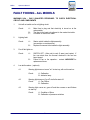
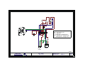
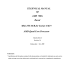
VLF 6
Vertical Clean Air Laminar Flow Cabinet
Operators Manual
Issue 03 – October 2010
Puricore International Ltd 175 Kenn Road Clevedon North Somerset BS21 6LH
Tel +44 1275 793000 | Fax +44 1275 341313 | [email protected] | www.puricore.com
Registered in England No: 2695450
CE Marking certifies that this equipment conforms to the following
EEC directives: Low Voltage Equipment – 72/23/EEC & 93/68 EEC
Electromagnetic Compatibility – 89/336/EEC
Certificate No: 0954499
CONTENTS
INTRODUCTION ........................................................................................................ 3
INSTALLATION AND OPERATION ............................................................................. 4
OPERATION ........................................................................................................................4
FILTERS .................................................................................................................... 5
Pre-filter ..............................................................................................................................5
Main Filter ...........................................................................................................................5
AIRFLOW.............................................................................................................................6
AIRFLOW MONITORING ......................................................................................................6
SERVICING................................................................................................................ 7
MAINTENANCE ......................................................................................................... 8
FAULT FINDING - ALL MODELS ................................................................................. 9
VLF 6
Operators Manual
INTRODUCTION
The Airflow is drawn through a Pre-filter on the top of the
cabinet through the fan to a plenum chamber behind the
Main filter. The air then passes through the filter at the
top of the Cabinet and out of the working aperture.
The filter seals are maintained under a negative
pressure so that it is not possible for unfiltered air to
pass the seal into the Cabinet.
Airflow is considered laminar between 0.35 to 0.55
m/sec.
3
VLF 6
Operators Manual
INSTALLATION AND OPERATION
The unit will be supplied ready assembled and with the correctly fused mains 3 pin plug
fitted. The unit can only be connected to the mains supply as follows:
Brown - 220/240V, Blue - Neutral
Green/Yellow to Earth
IMPORTANT
THIS APPLIANCE MUST BE EARTHED
OPERATION
The cabinet is fitted with the following controls and instrumentation:
a)
b)
c)
Mains on/off rocker switch
Lighting switch on/off
Fan high/low speed rotary switch
The unit is started by switching on the mains rocker switch and the light switch.
NOTES
1
Bunsen burners MUST NOT be placed within 200mm of the glazing or 'HEPA'
filter, the flame kept below 100mm high and MUST NOT come into contact with
the back or roof of the cabinet which could damage the HEPA filter.
4
VLF 6
Operators Manual
FILTERS
PRE-FILTER
The pre-filter is mounted on the top of the cabinet and will require occasional
replacement. The filter grade is EU7.
To change pre-filters:
1
Switch off the mains power supply.
2
Remove both thumbscrews on the head of the cabinet.
3
Slide top panel backwards 30mm (approx) to disengage rear overlap and
remove top panel.
4
Replace pre-filter. NOTE: the filter is graded and should be installed with
coloured surface uppermost.
5
Replace top panel on head unit 30mm (approx) to the rear. Slide panel forwards
with top panel under the rear overlap.
6
Replace thumbscrews.
7
Switch on mains power supply.
MAIN FILTER
The main filter is mounted from the top of the cabinet and the seals are under negative
pressure to avoid leakage into the cabinet. The filter is 99.997% efficient against 0.3
micron particles.
To replace the main filter, disconnect light lead at rear, unlock the side latches and lift
off the head unit.
5
VLF 6
Operators Manual
AIRFLOW
The airflow is preset and not adjustable. If the airflow drops below 0.3M/sec change the
airspeed switch to high. This will extend the life of the filter.
AIRFLOW MONITORING
The airflow should be checked at 6 monthly intervals with a rotary vane anemometer, at
a distance of about 100mm from the filter face. Adjust the airspeed if it is outside the
above levels. (Please check/replace the pre-filter prior to checking the airflow).
6
VLF 6
Operators Manual
SERVICING
An annual service is recommended and will cover the following points:
a)
Airflow check.
b)
Replace pre-filter if required.
c)
Filter condition check by D.O.P.
d)
Inspection of electrical components, lighting, cables etc
e)
Cleaning and checking the condition of the glazing
f)
Examination of services if fitted. The gas supply line must be checked carefully
for leaks and damage is fitted
g)
Issuing of a test report complete with an airflow certificate
Labcaire have a national team of service engineers who can offer a comprehensive
service at very competitive rates on all types of equipment from air purifiers and fume
cupboards to safety cabinets and to clean rooms.
Should you require further details please fill in the enclosed form and return it to us
marked for the attention of our Customer Services Department.
7
VLF 6
Operators Manual
MAINTENANCE
WARNING - Removal of the panel will expose electrical contacts. Disconnect electrical
supply before opening.
a)
FILTERS - The pre-filter requires occasional replacement.
b)
AIRFLOW - The Airflow will require checking at routine intervals. See section on
Airflow.
c)
LIGHTING - The lighting is accessible from back of the Cabinet. The units are
complete with starter and choke.
8
VLF 6
Operators Manual
FAULT FINDING - ALL MODELS
WARNING 240v - ONLY QUALIFIED PERSONNEL TO CHECK ELECTRICAL
CIRCUIT AND COMPONENTS
1
Unit will not switch on fan or lighting circuit.
Check:
ABC-
2
Lighting fault.
Check:
AB-
3
Starter switch inside the light assembly
(see section on maintenance).
Replace fluorescent tube inside the light assembly.
Fan off but lights on.
Check:
AB-
4
Main fuse in plug and that electricity is turned on at the
mains switch.
The fuse in the head unit adjacent to the mains inlet cable.
Condition of mains inlet cable.
SWITCH OFF - Allow unit to cool (if warm) and restart. If
fan now starts then the thermal overload in the fan has
been tripped.
Failure of fan or fan capacitor - contact LABCAIRE for
replacement items.
Low airflow alarm - (optional)
4.1
Warning light does not come "on" at start up, with unit turned on:
Check:
A - Calibration
B - Indicator lamp
4.2
Warning light does not "go off" at all after start off:
Check:
A - Fan Failure
B - Calibration
4.3
Warning light comes on, goes off and then comes on and flickers
on start up:
Check:
A - Condition of filters
B - Calibration of pressure switches
9
SW1
SW2
SW3
C
Normal
High
R1
1
2
3
4
5
6
7
8
SW1 = Mains sw't
SW2 = Fan high/low sw't
SW3 = Light sw't
F1 = 3A @ 230V ( 6.3A @ 110V)
CAP = 5uF @ 230V ( 10uF @ 110V)
R1 = 120R @ 230V ( 15R @ 110V)
9
Cap
F1
MAINS
FILTER
N
E
L
Light
socket
E
L
N
230/110V
AC SUPPLY
23/4/01
LABCAIRE
For Tomorrow's Environment
VLF6
PRODUCTION
DRAWING No
GJB-16
ISSUE
B
Puricore International Ltd
175 Kenn Road, Clevedon, North Somerset, BS21 6LH England
UK Tel:
INT Tel:
(01275) 793000
+44 1275 793000
E-mail:
[email protected]
Website:
http://www.puricore.com
VLF 6
Operators Manual
UK Fax:
INT Fax:
(01275) 341313
+44 1275 341313
October 2010
Issue 03