1
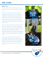
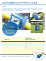
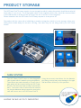
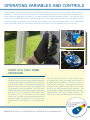
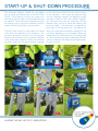
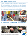
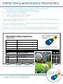
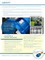
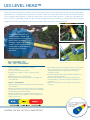
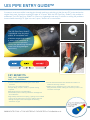
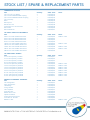
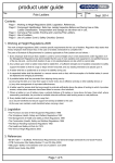
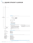
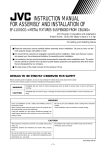
UIS Power Push™ Pipe Pusher 63mm > 180mm & 200mm > 400mm Models OPERATORS MANUAL Leading the way in Utility Innovations WELCOME ABOUT US Utility Innovations Solutions Limited (UIS Ltd) are specialists in manufacturing new innovations equipment for the utilities sector. Within the staff employed at UIS Ltd, we have a wealth of experience in gas, water and electricity replacement, rehabilitation and reinforcement projects. Our experience has enabled us to target key areas and functions within utilities we feel we can improve upon with new innovations created and manufactured in house. Although we are a relatively new company, our progression over the short time has been rapid, with interest and demand for our products being very high. The concept of UIS Ltd is to develop and advance innovation products that aid the process of replacing / renewing pipe utility work. A main aim is that all of our products should eradicate the inherent safety and technical faults encountered by existing methods. Aligned to safety, quality and engineering compliances there are also productivity benefits that allows our products to be compliant, versatile and proven speedier than alternative approved methods of works within utilities. As our products have been developed through extensive trials, a detailed technical assessment has been made in which includes a detailed analysis of its performance against alternatives. The use of this equipment may be adapted to water, gas and cabling activities or any other use for the process of insertion and a / best practice / information is provided. LEADING THE WAY IN UTILITY INNOVATIONS UIS POWER PUSH™ PIPE PUSHER SCOPE The purpose of this operators manual is to demonstrate the safe working process and procedure of the UIS Power Push™ Pipe Pusher. In this operators manual you will find all of the safe working practices which are required for using the product for its designed purpose. BENEFITS • Safety • Environmental migration • Standard & custom made shims both for small 63mm>180mm model and large 200mm>400mm model • Engineering compliant • Multi-use attachment tool GENERAL The UIS Power Push™ is an attachment which fits onto an excavator and is used for inserting new polyethylene pipe on predominantly gas and water sites. The UIS Power Push™ may also used for inserting cables through ducting, and can be used as an alignment clamp. SYMBOLS & ABBREVIATIONS UIS – Utility Innovations Solutions PP – Power Push™ PPE – Personal Protective Equipment 1.5T – 1.5 Tonne Excavator 3T – 3 Tonne Excavator 5T – 5 Tonne Excavator SDR Range – Standard Dimension Ratio PE – Polyethylene WWW.UISLTD.CO.UK • T 0161 428 7959 • F 0161 428 7933 • E [email protected] CONTENTS • Chapter 1 - Design Basis & Specification • Chapter 2 - Product Storage • Chapter 3 - Shim System • Chapter 4 - Operating Variables & Controls • Chapter 5 - Start-up & Shut-down Procedure • Chapter 6 - Equipment Operation • Chapter 7 - Emergency Shut Down Procedure • Chapter 8 - Inspection & Maintenance Procedures • Chapter 9 - Safety • Chapter 10 - Advisories & Control Measures • Chapter 11 - Additional Extras - The UIS Level Head™ • Chapter 12 - Additional Extras - The UIS Pipe Entry Guide™ • Chapter 13 - Stock List / Spare & Replacement Parts LEADING THE WAY IN UTILITY INNOVATIONS DESIGN BASIS & SPECIFICATIONS The UIS Power Push™ has been designed, tested and implemented to suit the needs of small / large scale gas / water / electric mains replacement schemes. SPECIFICATIONS & RECOMMENDATIONS 63mm > 180mm Pipe Pusher • Weight – 46KG • Height – 420mm • Length – 310mm • Width – 335mm • Jaw Opening Width – 100mm • Clamping Force – 1200KGF • Recommended Working Pressure – 200 Bar Max • Recommended Excavator Size: ·Excavator Size – 1.5T Pipe Diameter 63mm/75mm/90mm/110mm&125mm SDR Range – 11 & 17.6 ·Excavator Size – 3T Pipe Diameter – 140mm/160mm/180mm SDR Range – 11 & 17.6 1. 2. 3. 4. 5. 6. 7. 8. 200mm > 400mm Pipe Pusher • Weight – 172KG • Height – 600mm • Length – 460mm • Width – 590mm • Jaw Opening Width – 180mm • Clamping Force – 5000KGF • Recommended Working Pressure – 200 Bar Max • Recommended Excavator Size: ·Excavator Size – 3T & 5T Carrier Head Bracket & Pin 4 Bolt Plate Connection Hydraulic Cylinders Lock Mechanism Clamp Pivot Point Shim Inserts Flat Stand Plate Ram Guard WWW.UISLTD.CO.UK • T 0161 428 7959 • F 0161 428 7933 • E [email protected] PRODUCT STORAGE The UIS Power Push™ comes stored in its own storage box which is where the product should be stored at all times when it is not in use. The lifting handle, which is also supplied with the unit, should be connected back to the head bracket to aid the process of lifting of the unit in and out of the storage box. Please remember that the UIS Power Push™ always equates to a two person lift. The product will also come with a holdall bag or another storage box, which is for the storage of shim sets. These shims should always be stored in the bag / box when they are not being used by the UIS Power Push™. SHIM SYSTEM The UIS Power Push™ uses an interchangeable shim system which is made from recycled plastics. These shims are made internally to fit each size of pipe which will be inserted using the UIS Power Push™. The shims are fixed in using 5 countersunk bolts. The correct size of shims must be inserted for the pipe diameter being inserted to ensure the safe and correct use of the UIS Power Push™. LEADING THE WAY IN UTILITY INNOVATIONS Using the incorrect sized shims for the diameter pipe being inserted may cause damage to the pipe wall and effect efficiency of the operation. OPERATING VARIABLES AND CONTROLS The operations of the UIS Power Push™ are all done through the operations of the excavator which the unit is attached to. These are the same controls that the excavator operator would use to operate the excavator in the same manner as digging an excavation or using an excavator mounted hydraulic breaker. The open and close function on the UIS Power Push™ is done through the use of the dual flow hydraulics on the excavator, which is either through a foot pedal on the excavator or through a button on the operating levers. This is dependent on the make and model of the excavator which the UIS Power Push™ is attached to as this may vary. START-UP & SHUT-DOWN PROCEDURE The UIS Power Push™ fits onto an excavator in the same way as an excavator bucket, hydraulic breaker or other attachments are fitted, which is via pins or a quick hitch system. The universal head bracket which is fitted to the UIS Power Push™ allows it to fit the majority of mini excavators. This UIS Power Push™ can also be fitted to different size excavators such as a 3T or 5T. Should the UIS Power Push™ be used on a 3T or 5T excavator, then UIS would need to be informed of the excavator type before operation begins to enable UIS to fit the correct head bracket to the excavator if not already done so. The UIS Power Push™ is to be removed from its storage box using the lifting handle which is provided with the product. The unit is strictly a 2 person lift at all times. Once removed from the storage box, the product can be placed on the floor and then the lifting handle can be removed. The lifting handle is simply removed by taking out the 2 retaining clips / lynch pins holding it in place. The unit is now ready to be attached to the excavator. WWW.UISLTD.CO.UK • T 0161 428 7959 • F 0161 428 7933 • E [email protected] START-UP & SHUT-DOWN PROCEDURE continued The excavator operator should line the dipper arm up inside the head bracket of the UIS Power Push™. Once lined up, the pins are ready to be inserted through the holes on the head bracket and the machine. Once these pins have been inserted, the retaining clips / lynch pins should be fitted to ensure the unit stays safely to the excavator. The UIS Power Push™ is now ready to be fitted to the dual flow hydraulics of the excavator. The excavator should be turned off for this process, ensuring all pressures on the auxiliary hydraulic circuits have been released. When the excavator has been turned off, the quick release couplings LEADING THE WAY IN UTILITY INNOVATIONS on the UIS Power Push™ can be fitted to those on the excavator. This is done by simply pushing the two couplings together and applying enough pressure to them so that they connect together, you will know that they are connected securely because there will be a small ball bearing that becomes visible. This operation is completed on both sides of the excavator arm. Normally there will be one male and one female coupling, but this can differ depending on the excavator make and model which the UIS Power Push™ is being fitted to. The excavator must have a dual flow hydraulic system to allow the UIS Power Push™ pipe pusher to work correctly. EQUIPMENT OPERATION The excavator should be positioned at the edge of the excavation where the new polyethylene pipe / cable is going to be inserted from. Once the excavator is in the correct position with the UIS Power Push™ fitted, the new polyethylene pipe / cable can start to be inserted inside the carrier main / ducting. There must be a banks man in contact with the excavator operator at all times to ensure the safe insertion of the polyethylene pipe / cable. The UIS Power Push™ is used to push / pull the pipe into the carrier main / ducting, when the excavator arm is at the edge of the excavation and can no longer move and further back, the excavator operator then pushes the dual flow hydraulic pedal / button, which opens up the UIS Power Push™ allowing the machine driver to slide the excavator arm back up the pipe / cable as far as the excavator arm will reach. The dual flow hydraulics on the excavator are then used again this time closing the UIS Power Push™ which in turn grips the pipe. The same process is then repeated until the insertion length of pipe / cable is achieved. EMERGENCY SHUT DOWN PROCEDURE In case of any emergencies whilst using the UIS Power Push™, the most efficient way of shutting down all operations is to turn off the excavator using the key. This operation will stop all workings of the excavator and also stop the flow of hydraulic oil to the UIS Power Push™. WWW.UISLTD.CO.UK • T 0161 428 7959 • F 0161 428 7933 • E [email protected] INSPECTION & MAINTENANCE PROCEDURES The UIS Power Push™ should be inspected prior to every use using the following checks: • Hydraulic Hoses and Connections should be checked for leaks • Head Bracket / Pins for Head Bracket [correct pins for machine] • Condition of Shims [free from debris] • 4 Bolts on Head Bracket [all in place and secure] • All 5 countersunk bolts in place for shims Daily maintenance checks should be carried out in accordance with the ‘UIS Operators Daily Inspection’ checklist, which are supplied by UIS Ltd. If you suspect that there are any problems / faults with your UIS Power Push™, then either contact your site supervisor or UIS Ltd direct on 0161 428 7959. If you have the UIS Power Push™ on a long term hire, after a 6 month period the unit will be recalled by UIS Ltd for a 6 month inspection where the unit will be thoroughly checked and serviced by a competent person. Operators Daily Inspection Check Sheet Name: Week Commencing Date: Company: Plant Number: Item Description: Note: Item: The below checks MUST be completed prior to and during the use of the product. If any of the inspections result in fail, STOP and report it to your supervisor immediately prior to use. Mon Tue Wed Thu Fri Sat Sun Check to be performed: Generic Inspection Checks Hydraulic Rams 2 Hydraulic Hoses 3 Hydraulic Connectors · Correct connectors, which are free from dirt/debris? 4 Head Bracket · Free from signs of damage/stress? · Swivel unit free from obstructions and fit for use? · Head bracket locking in place and satisfactory? · Locking nuts in place and free from wear? 6 Locking Mechanism · Fixing lugs in place and free from wear? fit the head bracket satisfactory? just aPins section one of our· Pins Operators Daily Inspection Sheets 7 [Safetyof Clips] · 2 x Safety pins in place? · Does the site provide sufficient access to deploy and 8 Site Conditions operate the Excavator [if applicable] and UIS product? · Operatives wearing the correct PPE as stated within 9 PPE the Operators Manual and site specific requirements set by contract? · All necessary documentation including UIS product 10 Paperwork Operators Manual for additional guidance? · Excavator operator competent in the use of the 11 Operator Competence Excavator [if applicable] and UIS product? UIS Power Push™ Inspection Checks · Shim set[s] gripping and releasing the PE main as 12 Shim Set required? · Shim set[s] free from signs of damage/stress? H Link · H Link in place and fits to unit head bracket? 13 Manual Lifting Aid · 2 person lift sign displayed? Storage Box[s] / 14 · Good condition dressed / painted? Bag[s] 5 This is · Pressure test completed and satisfactory? · Visual condition satisfactory? · Pressure test completed and satisfactory? · Visual condition satisfactory? · Free from outer casing damage? 1 Swivel Unit LEADING THE WAY IN UTILITY INNOVATIONS SAFETY To be using the UIS Power Push™ in the safe and correct manner, the operator should have completed the following before using the equipment: • Make sure the person using the Carrier Excavator has all of the correct qualifications and is competent in the use of an excavator. • Make sure the correct PPE is being worn, items such as Safety Glasses, Hard Hat, Safety Toe Cap Boots, High Visibility Work Wear and Protective Gloves. Additional PPE may be required dependant on Site Specific requirements. • Ensure it is as safe working environment before attaching the product to the carrier excavator, i.e. inside a clear and safe area away from members of public etc. Please note that using the attachment outside the parameters of the information contained in this manual may cause harm, disruption and damage. SAFETY MANAGEMENT SYSTEM RISK ASSESSMENT Client: Date: 01/11/2012 Doc No: UIS/QMS/010 Contract: ACTIVITY: General Risk Assessment: Use of UIS Power Push™ [Insertion /Alignment and correction of PE Pipe] Activity affecting (Tick appropriate box) 1 2 Lifting – Mechanical handling operations EMPLOYEE THIRD PARTY VEHICLE 4 x 3 = 12 5 x 5 = 25 Moving parts of machinery Crush injuries/death Working in close proximity to live apparatus Impact Damage To Pipe work causing uncontrolled release of gas. 4 Pressurised system [Hydraulics] Un controlled release of high pressure hydraulics causing injury and possible damage to the environment. 6 Use of hand tools Traffic & General Construction Hazard PLANT Impact injury, crushing, damage to property and plant. Collapse/overturning of lifting plant 3 5 Personal injury to operatives/users 6 x 5 = 30 2x3=6 3x2=6 Collision, crushing, trips & falls 6 x 4 = 24 PROPERTY RISK RATING FREQUENCY X SEVERITY All lifting equipment must have in date certificate and bear current colour coding and be inspected prior to being used so as to comply with LOLER regulations. 1. All lifting equipment is examined before use, with defective equipment being removed from site. 2. The driver/operator must have an in date CITB/CPCS card. Weekly lifting equipment registers to have been completed. 3. Speed of operations dictated by Specific Site Conditions. 4. Ensure that outriggers are deployed and machine is sited on good firm ground. A competent person must assume the role of a slinger/signaller and take precautions to ensure others are kept away from lifting operations 1. Drivers to be aware of Permit to Work controls and restrictions. 2. Live gas pipelines to be protected against impact damage. 3. Banksman to control close working. 4. Underground services to be protected. 5. Site set out to restrict public access (barriers/herras fencing) 6. All works to be contained within the site area no working over live footpaths or traffic. 1. Mechanical excavators to work within demarcated site, no swinging buckets across or into live carriageway. 2. Any existing gas pipe and other utilities to be adequately protected against accidental contact/damage. Machinery to be adequately maintained. Operator to perform pre-start checks of all connectors No excessive pressure to be applied. Spill kits to be readily available. 1. Training given in the correct handling and use of hand tools 2. Correct maintenance of hand tools, , Replace or maintain as necessary 3. Use the correct tool for the job and appropriate PPE, e.g. gloves, eye protection etc. as instructed. 1. 2. = 7 9 3x3=9 6 6x1=6 4 2x2=4 4 2x2=4 Full compliance with NRSWA Site barriered off, signed and guarded with appropriate signs, care for the pedestrian. 5 x 3 = 15 Compiled By: David G Stevens Signature(s): D G Stevens Date: 1 November 2012 Reviewed by: J J Iredale Signature: J J Iredale Date: 1 November 2012 Note: All employees are to be informed of control measures prior to work commencing. Page 1 of 2 ADVISORIES & CONTROL MEASURES •The product not to be used as a lifting aid at any time •The driver / operator must have a valid CITB / CPCS card •Speed of operations dictated by specific site conditions •The excavator must be sited on good firm ground •Drivers to be aware of Permit to Work controls and restrictions •Live gas pipelines to be protected against impact damage •Banksman to control close working •Underground services to be protected •Site set out to restrict public access (barriers/herras fencing) •All works to be contained within the site area no working over live footpaths or traffic •Mechanical excavators to work within demarcated site, no swinging buckets across or into live carriageway •Any existing gas pipe and other utilities to be adequately protected against accidental contact / damage •Machinery to be adequately maintained •Operator to perform pre-start checks of all connectors •No excessive pressure to be applied •Spill kits to be readily available •Training given in the correct handling and use of hand tools •Correct maintenance of hand tools. Replace or maintain as necessary •Use the correct tool for the job and appropriate PPE, e.g. gloves, eye protection etc. as instructed •Full compliance with NRSWA (New Roads and Streetworks Act) •Site barriered off, signed and guarded with appropriate signs, care for the pedestrian WWW.UISLTD.CO.UK • T 0161 428 7959 • F 0161 428 7933 • E [email protected] UIS LEVEL HEAD™ Historically there have been a number of serious personal injuries / near misses associated with the handling and manipulation of coiled pipe during insertion activities. One of the major difficulties encountered whilst pushing / inserting and winching pipe is when the new main comes into an open service / connection excavation pit. Due to the P.E. pipe being coiled, this has natural energised pressure resulting in the pipe naturally springing upwards. The UIS Level Head™ resolves this problem with ease and is simple to install. The UIS Level Head™ is a approximately 1 meter long weighted section of recycled plastic that is available in all diameter ranges that enables a safer, more compliant and sustainable product allowing a more fluent insertion operation. KEY BENEFITS TIME · COST · ENVIRONMENT •Can be installed onto lead end of coiled pipe within 2 minutes •Low cost / very effective product •Simple design, simple to install, no special training required •Manufactured from recycled plastics •Sustainable product reducing overall P.E. wastage and associated time SAFETY · ENGINEERING •Significantly reduces stored energy contained in lead end of coiled pipes •Eliminates operatives entering excavations to manipulate pipe through the next host section of main due to the pipes natural energy contained in the end •Enables the handling of coiled pipe easier and safer on ground surface in the preparation of the coiled pipe from trailer to host main LEADING THE WAY IN UTILITY INNOVATIONS •Significantly reduces the scraping / grating of the inserted pipe on the up-side of the host main, reducing the wall damage throughout the inserted pipe and ensuring cleanliness of pipe •Could be utilised and have same benefits and effects for traditional winching activities •The UIS Level Head™ has more enhanced protection thus eliminating cut back and wastage in preparation for connections •Reduces overall tension and resistance encountered in insertions UIS PIPE ENTRY GUIDE™ A common occurrence whilst inserting pipe through pushing or winching is that the new P.E. main catches the original host main, therefore scraping the pipe as it enters. With the UIS Pipe Entry Guide™, this problem is eradicated. The UIS Pipe Entry Guide™ is a low-cost, lightweight and easy fit solution to solving the problems incurred while inserting P.E. pipe into cast / spun / ductile iron or steel mains. The UIS Pipe Entry Guide™ is produced from recycled plastic & is available in all diameter ranges that enables a safer, more compliant & fluent insertion operation whilst also preventing the new main from being damaged upon entry. KEY BENEFITS TIME · COST · ENVIRONMENT SAFETY · ENGINEERING •Can be installed onto the existing host main within 2 minutes •Low cost / very effective product •Simple design, simple to install, no special training required •Manufactured from recycled plastics •Sustainable product reducing overall P.E. wastage and associated time •Significantly reduces the scraping / grating of the inserted pipe on the up-side of the host main, reducing the wall damage throughout the inserted pipe and ensuring cleanliness of pipe •Can be utilised and have same benefits and effects for traditional winching activities •Making sure no damage occurs to the new P.E. main being inserted, and also making the insertion process a lot smoother and simple WWW.UISLTD.CO.UK • T 0161 428 7959 • F 0161 428 7933 • E [email protected] STOCK LIST / SPARE & REPLACEMENT PARTS HEAD Item 1.5 Tonne Universal Head 3 Tonne Universal Head 5 Tonne Universal Head Head Reducer Bushes 25mm Head Attachment Pins 30mm Head Attachment Pins 35mm Head Attachment Pins 40mm Head Attachment Pins 6mm Lynch Pins 16mm Lock Nuts Retaining Washer Nylon Head Wear Shim Quantity 1 1 1 4 2 2 2 2 2 4 1 1 Order Code UIS/PP/001 UIS/PP/002 UIS/PP/003 UIS/PP/004 UIS/PP/005 UIS/PP/006 UIS/PP/007 UIS/PP/008 UIS/PP/009 UIS/PP/010 UIS/PP/011 UIS/PP/012 Notes FRAME Item 12mm Hinge Pin 12mm Hinge Nut Bottom Pin Clamp Plates [Side Swivel Plate] 10 x 30 Plate Bolts Quantity 1 1 2 4 Order Code UIS/PP/013 UIS/PP/014 UIS/PP/015 UIS/PP/016 Notes SHIM SETS Item 50mm with Counter Sunk Bolts 63mm with Counter Sunk Bolts 75mm with Counter Sunk Bolts 90mm with Counter Sunk Bolts 110mm with Counter Sunk Bolts 125mm with Counter Sunk Bolts 140mm with Counter Sunk Bolts 160mm with Counter Sunk Bolts 180mm with Counter Sunk Bolts 200mm with Counter Sunk Bolts 213mm with Counter Sunk Bolts 215mm with Counter Sunk Bolts 225mm with Counter Sunk Bolts 250mm with Counter Sunk Bolts 300mm with Counter Sunk Bolts 315mm with Counter Sunk Bolts 355mm with Counter Sunk Bolts 400mm with Counter Sunk Bolts Quantity 2 2 2 2 2 2 2 2 2 2 2 2 2 2 2 2 2 2 Order Code UIS/PP/017 UIS/PP/018 UIS/PP/019 UIS/PP/020 UIS/PP/021 UIS/PP/022 UIS/PP/023 UIS/PP/024 UIS/PP/025 UIS/PP/026 UIS/PP/027 UIS/PP/028 UIS/PP/029 UIS/PP/030 UIS/PP/031 UIS/PP/032 UIS/PP/033 UIS/PP/034 Notes Made to order SHIM CLAMPING BOLTS Item Counter Sunk Bolts Quantity 6 Order Code UIS/PP/035 Notes Made to order Quantity 2 2 2 2 4 6 Order Code UIS/PP/036 UIS/PP/037 UIS/PP/038 UIS/PP/039 UIS/PP/040 UIS/PP/041 Notes HYDRAULICS Item Feed Hose 1/4 inch Bulk Head Fittings Link Hose Tea Adaptor Male / Female Adaptor Dowty Washer Continued over page LEADING THE WAY IN UTILITY INNOVATIONS Made to order Made to order Made to order Made to order Made to order Made to order Made to order Made to order Made to order STOCK LIST / SPARE & REPLACEMENT PARTS HYDRAULICS Continued Item 1/2 inch x 1/4 inch Adaptor 1/2 inch Quick Release Male Coupling 1/2 inch Quick Release Female Coupling 1/2 inch Dowty Rams Ram Top Pin Ram Bottom Pin 6mm Bottom Pin Grub Screws Ram Guard Ram Guard Bolts Quantity 2 1 1 2 2 1 1 2 1 2 Order Code UIS/PP/042 UIS/PP/043 UIS/PP/044 UIS/PP/045 UIS/PP/046 UIS/PP/047 UIS/PP/048 UIS/PP/049 UIS/PP/050 UIS/PP/051 Notes UIS LEVEL HEAD™ ATTACHMENTS Item 50mm UIS Level Head™ Attachment 63mm UIS Level Head™ Attachment 75mm UIS Level Head™ Attachment 90mm UIS Level Head™ Attachment 110mm UIS Level Head™ Attachment 125mm UIS Level Head™ Attachment 140mm UIS Level Head™ Attachment 160mm UIS Level Head™ Attachment 180mm UIS Level Head™ Attachment Quantity 1 1 1 1 1 1 1 1 1 Order Code UIS/PP/052 UIS/PP/053 UIS/PP/054 UIS/PP/055 UIS/PP/056 UIS/PP/057 UIS/PP/058 UIS/PP/059 UIS/PP/060 Notes Made to order UIS PIPE ENTRY GUIDE™ Item 3 inch UIS Pipe Entry Guide™ 4 inch UIS Pipe Entry Guide™ 6 inch UIS Pipe Entry Guide™ 8 inch UIS Pipe Entry Guide™ 10 inch UIS Pipe Entry Guide™ 12 inch UIS Pipe Entry Guide™ 14 inch UIS Pipe Entry Guide™ 16 inch UIS Pipe Entry Guide™ 18 inch UIS Pipe Entry Guide™ 20 inch UIS Pipe Entry Guide™ 22 inch UIS Pipe Entry Guide™ 24 inch UIS Pipe Entry Guide™ Quantity 1 1 1 1 1 1 1 1 1 1 1 1 Order Code UIS/PP/061 UIS/PP/062 UIS/PP/063 UIS/PP/064 UIS/PP/065 UIS/PP/066 UIS/PP/067 UIS/PP/068 UIS/PP/069 UIS/PP/070 UIS/PP/071 UIS/PP/072 Notes PRODUCT STORAGE & CONTENTS Item Unit Storage Box Shim Storage Box Holdall Bag Lifting Handles 17mm Spanner 5mm Allen Key Rubber Floor Liner Operators Manual Product Risk Assessment ‘Two Man Lift’ Stickers Wheels for Box Quantity 1 1 1 2 1 1 1 1 1 2 2 Order Code UIS/PP/073 UIS/PP/074 UIS/PP/075 UIS/PP/076 UIS/PP/077 UIS/PP/078 UIS/PP/079 UIS/PP/080 UIS/PP/081 UIS/PP/082 UIS/PP/083 Notes Made to order Made to order Made to order Made to order Made to order Made to order Made to order Made to order Made to order Made to order Made to order Made to order WWW.UISLTD.CO.UK • T 0161 428 7959 • F 0161 428 7933 • E [email protected] Utility Innovations Solutions Limited are proud sponsors, members & affiliates of the following organisations: Utility Innovations Solutions Limited Unit 2, Hargreaves Court, Hargreaves Road, Northwich, Cheshire CW9 7BL Telephone: 0161 428 7959 • Fax: 0161 428 7933 • Email: [email protected] • Web: uisltd.co.uk facebook.com/uisltd • twitter.com/uisltd