1
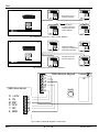
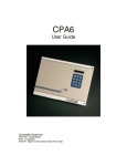
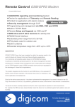
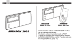
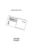
TS800
Installation & User Guide
Compatible Equipment
CPA6 OM - Output Module
9040 - Loudspeaker
DC54/58 - Digital Communicator (Stand alone only)
LEC8 - 8 Zone Expander
496528 Issue A
1 of 10
TS800
TS800
Overview
Introduction
5
The TS800 Intruder Alarm control system is provided for
domestic and commercial alarm systems conforming
to BS 4737: Part 1 1986. There are two versions of the
Control Panel:
(1)
(2)
The Intruder Alarm Control Panel TS800 is a self
contained unit with a 2 x 16 digit backlit liquid
crystal display (LCD), a tactile backlit keypad, an
internal sounder, its own power supply and
connections for a standby battery for operation
during a mains failure. In its basic form it will
monitor up to eight circuits and can be
expanded to monitor 16 circuits when a Local
Expansion Card (LEC8) is connected. The
system may also be controlled from a Remote
Keypad (TS800.REM) if required (up to 4 may be
fitted to a system).
Printer: A printer type CPA6.P or other standard
RS232 serial printers via a Menvier Security Printer
Adapter (MPA) may be connected to provide a
printout of 200 log events and system
parameters.
Specification
Panel input Voltage:
Panel Current Cons.:
240V +/- 10% 50Hz
75mA (normal);
200mA (In Alarm)
Remote Keypad
15mA (normal); 35mA (In
Current Cons.:
Alarm)
Battery:
12V 6ah sealed lead
acid
Zones:
8 (standard); 16 using a
LEC
Auxiliary 12V output:
750mA
The Intruder Alarm Control Panel TS800R is similar Control Panel Dim.:
325 (L) x 265 (H) x 80 (D) mm
to the TS800 but has no front panel keypad or Control Panel Weight:
3kg
display hence it requires at least one Remote Remote keypad Dim.: 130 (L) x 130 (H) x 30 (D) mm
Keypad (TS800.REM) to control it.
Remote keypad weight: 200g
Environment:
0 - 55 deg C
Options
1
Local Expansion Card (LEC8): A LEC may
be fitted inside the panel and will provide the
facility to monitor eight additional circuits so
that a total of 16 circuits may be monitored by
the panel;
2
Remote Keypad (TS800 REM): These units,
consisting of a tactile backlit keypad, backlit
LCD and internal sounder, are used at a
remote location to control the main panel. A
maximum of four Remote Keypads may be
connected;
3
Output Module (CPA6 OM): These units may
be connected to the panel and are used to
provide an output to a set of LEDs to indicate
alarm activations. Each module will provide
up to eight zone indications and may be ‘daisy
chained’ if more outputs are required (a
maximum of 2);
4
Digital Communicator: A Digicom type DC28
or similar may be fitted inside the panel to
transfer panel status information to a
dedicated Central Station via BT lines:
TS800
2 of 10
496528 Issue A
TS800
Main PCB Layout
LEC8
Digicom DC28
(under)
DC 28
Novram
To B.T. Line
PL 2
Main Board
6 Ah Battery
NOTE: not fitted
on the TS800R
Loud
Speaker
(under)
Mains
Terminals
Fig 1 TS800 Panel Layout
Output Module
JP5
JP4
Outputs for Bell, Strobe,
Fire Reset, Aux Output
and Aux Tamper input.
Terminals for Digicom
DC28 connector
MIN
MAX
Sounder Volume adjust
Vol
LCD
LK 1
Terminals for
Circuits 1-8
LK 2
Jp1
Remote Keypad
Connections
Tamper
switch
Remote
Novram
Local Expansion
Card (LEC8)
LINKS
LK.1: Factory Default
LK.2: Digicom Reset/Test
LK.3: TH Link
LK.4: Walk Test polarity
FUSES
F1: 2A Sounder supply
F2: 160mA Mains input
F3: 1A QB Aux supply
F4: 1A QB Bell Supply
LK3
Printer CPA6 or RS 232 via
Menvier Security Printer adapter
JP2
F1: 2A
F3: 1A
F4: 1A
Keypad
LK4
NEUTRAL
LIVE
EARTH
Outputs for Walk Test,
Extension
Loudspeakers
and Aux 12V
Mains Input
F2: 160mA
Battery
Earth
To Front cover
Fig 2 Main PCB Layout
496528 Issue A
3 of 10
TS800
TS800
Installing Detection and Tamper Circuits
The Detection circuits may be wired as EOLR (End of
line resistor) or DP (Double pole) and the methods may
be mixed on the same system.
EOLR System (Fig 3):
DP Wired System (Fig 4)
(1)
1)
Detector and tamper devices have normally
closed contacts in separate loops and are
connected to zone and tamper terminals
respectively;
2)
Each alarm loop and tamper loop resistance
must be less than l00 Ohms; .
3)
A maximum of I0 devices may be connected
in each loop;
4)
A normally open circuit, such as a Pressure Pad
or Exit Terminator switch, may also be
connected;
5)
Links can be fitted across the zone and tamper
loops if the circuit is not required or may be
programmed as SPARE in the DEFINE CIRCUITS
menu.
(2)
(3)
(4)
(5)
(6)
(7)
(8)
Detector devices have normally closed contacts
with a 4k7 shunt resistor;
Tamper devices have normally closed contacts
with no shunt resistor;
A 2k2 End Of Line (EOL) resistor must be fitted at the
point in the circuit furthest from the control panel;
Loop resistance with the EOL resistor shorted must
be less than 100 Ohms;
The circuit is connected between the upper zone
and lower tamper terminals;
The maximum number of devices allowed in a
circuit is ten;
A normally open device, such as a Pressure Pad or
Exit Terminator switch, may also be connected as
shown;
Links can be fitted across the zone and tamper
loops if the circuit is not required or may be
programmed as SPARE in the DEFINE CIRCUITS
menu.
Detector Sw
Detector Sw
4k7
4k7
Z1
Normally
open
contact
2k2
EOL
Res
Tamper Sw
TS 800 MAIN PCB
Circuit 1
T1
Tamper Sw
Z2
Circuit 2
Red Red Red
2k2 Resistor
Yellow Violet Red
T2
4k7 Resistor
Fig 3 EOLR Circuit Connections
TS800
4 of 10
496528 Issue A
TS800
TS800 MAIN PCB
Detector Sw
Detector Sw
Z1
Normally
open
contact
Circuit 1
Tamper Sw
T1
Tamper Sw
Fig 4 DP Wired Circuit Connections
Installing a Local Expansion Card (LEC8)
Installing Remote Keypads (TS800.REM)
If more than eight zones are required then a LEC8 is
fitted inside the TS800 case as follows:
At least one Remote Keypad is required for a TS800R
and up to four may be fitted at suitable locations with
cables connected to the main PCB ‘REMOTE’ terminals
using 6 core cable (Fig 7):
(1)
Fit the four posts supplied to the LEC8 PCB
then position the LEC in the base and secure it
by pushing the posts into the holes provided
(Fig 1);
(2)
Fit the connector supplied by connecting it
between JPI on the LEC8 and JPl on the
Control Panel main PCB (Fig 2);
(3)
Connect the detection circuit cables to the
LEC8 (Fig 3 and 4).
(1)
In a Daisy Chain configuration in which case the
cable length to the last Remote Keypad must
not exceed 100m to prevent excessive voltage
drop in the cables (Fig 5);
(2)
In a star configuration in which case the cable
between the Remote Keypad and Panel must
not exceed 100m to prevent excessive voltage
drop in the cables (Fig 6);
The PCB is secured to the cover by a screw. The base
and cover clip together.
496528 Issue A
(1)
Open the Remote Keypad case by using a
screwdriver to depress two of the retaining clips
inwards from their cover indents to release the
top or bottom then remove the cover complete
with its PCB;
(2)
Secure the Remote Keypad base in its required
location using the keyhole and two fixing holes
then feed the cable/s through the cable entry,
prepare the ends and connect them to the
terminal block on the Remote Keypad PCB.
(3)
When all the required Remote Keypads are
fitted and cables connected make the
connections at the main PCB.
5 of 10
TS800
TS800
BOARD ROOM
01 NIGHT Healthy
1 2
4 5
7 8
YES 0
0
BOARD ROOM
01 NIGHT Healthy
1
4
7
YES
0
2
5
8
0
3
6
9
NO
0
BOARD ROOM
01 NIGHT Healthy
3
6
9
NO
0
BOARD ROOM
01 NIGHT Healthy
1 2
4 5
7 8
YES 0
0
3
6
9
NO
0
All cables are 6 core
7/0.2mm minimum
Maximum total
length of cable from
Control Panel to this
point is 100mtrs.
1 2
4 5
7 8
YES 0
0
3
6
9
NO
0
BOARD ROOM
01 NIGHT Healthy
1 2
4 5
7 8
YES 0
0
3
6
9
NO
0
Fig 5 Remote Connection - Daisy Chain Method
BOARD ROOM
01 NIGHT Healthy
BOARD ROOM
01 NIGHT Healthy
1 2
4 5
7 8
YES 0
0
BOARD ROOM
01 NIGHT Healthy
1
4
7
YES
0
2
5
8
0
3
6
9
NO
0
3
6
9
NO
0
BOARD ROOM
01 NIGHT Healthy
1 2
4 5
7 8
YES 0
0
Maximum length of
cable from Control Panel
to Remotes is 100 mtrs
All cables are 6 core
7/0.2mm minimum
1 2
4 5
7 8
YES 0
0
BOARD ROOM
01 NIGHT Healthy
1 2
4 5
7 8
YES 0
0
3
6
9
NO
0
3
6
9
NO
0
3
6
9
NO
0
Fig 6 Remote Connection - Star Method
D
C
A
B
F
E
TS800 Main Board
R
E
M
O
T
E
+12V
0V
RSP
SCK
SIO
BUSY
TS 800 Remote Keypad
CONTRAST
TAMPER
F
E
D
C
B
A
Fig 7 Panel to Remote Keypad Connections
TS800
6 of 10
496528 Issue A
TS800
Factory Restart Default Values
When a control Panel is shipped from the factory the memory data default parameters are set to:
(1)
Engineer’s Code: 1234;
(2)
Master User’s Code: 5678;
(3)
Circuits 01 - 05: Night;
(4)
Circuit 06: Last Exit;
(5)
Circuit 07: Exit Terminator;
(6)
Circuit 08: Personal Attack:
(7)
Circuit 09 - 16: Spare;
(8)
All Circuits in Ward 1;
(9)
Entry Time: 20 seconds;
(10)
Exit Time: 20 seconds;
(11)
Bell Delay: 0 minutes;
(12)
Bell Duration: 20 minutes;
(13)
Double Knock Delay: 0 seconds;
(14)
Part Set Digi Delay: 90 seconds;
(15)
Codes: 4 digit;
(16)
System Reset: By User;
(17)
System Re-arm: Manual;
(18)
PA Alarm: Audible;
(19)
Omitting by: Engineer;
(20)
Full Set by: Circuit;
(21)
Part Set by: Circuit;
(22)
Setting Complete by : Last Exit;
(23)
Quiet Set: N/A;
(24)
Part Set Digi: Instant;
(25)
Algorithm Count: 004.
NOTE:
IF LINK LK1 IS CLOSED AT POWER-UP,
ALL INFORMATION WILL BE RESET TO THE DEFAULTS SHOWN ABOVE.
496528 Issue A
7 of 10
TS800
TS800
Key Functions
Engineer’s Reset
1.
Enter the engineer’s code default 1234. You are
now in Engineer’s Mode.
2.
Press 0 to return to unset.
System Reset
If link LK1, fitted on the Control Panel main board, is
OPEN it will ensure that if there is loss of power all the
data is retained and this is indicated by the ON SITE
RESTART message being displayed on power up. If the
link is CLOSED, and there is a loss of power, then all
data will be LOST as it will be replaced by the Factory
Restart default values. This is indicated by the FACTORY
RESTART message when power is restored.
☞
Once the system is powered Link LK1 should
be opened.
Preliminary Power Up
To power the system for the first time:
1.
Verify that link LK1 on the Control Panel is closed
to ensure Factory Defaults are set;
2.
Apply mains 240V ac power;
3.
Verify that the Control Panel and Remote
Keypads display FACTORY RESTART and sounder
operates;
4.
Enter the engineer’s passcode to silence the
sounder;
5.
Open LK1.
Bell Test/ Walk Test
Please refer to page 10
TS800
8 of 10
496528 Issue A
496528 Issue A
9 of 10
FROM
MENU 10
FROM
MENU 3
14
15
SELECT TEXT USED TO
IDENTIFY A CIRCUIT
1=A
2=E
3=I
4=O
5=U
6=0
7 = DOWN
8 = SPACE
9 = UP
0 = ACCEPT TEXT
YES = ACCEPT CHARACTER
NO = DELETE CHARACTER
Press YES to...
CHANGE TEXT
SELECT THE RESET
ALGORITHM
Press YES to...
ALTER RESET CALC
12
BACK TO
MENU 13
= Hotkey
PRINT PANEL DATA
PRINT EVENT LOG
(all events)
PRINT EVENT LOG
(selected)
NOTE: THIS MENU IS
ONLY AVAILABLE WHEN
A PRINTER IS
CONNECTED
ENABLES AND
DISABLES THE CHIME
FUNCTION
CHANGE THE SYSTEM
ENGINEER CODE
TEST SOUNDER BELL
AND STROBE
TEST DETECTION DEVICES
Circuits activated are
displayed in order
11
Press YES to...
USE THE PRINTER
Press YES to...
ENABLE CHIME
6
Press YES to...
CHANGE ENG CODE
9
2
CHANGE SYSTEM TIME
AND DATE
10
3
VIEW CIRCUIT STATUS
Healthy
Active
Tamper
Press YES to...
VIEW CIRCUITS
SELECT THE CIRCUITS
THAT WILL CHIME
WHEN ACTIVATED
Press YES to...
ALTER CHIME CCTS
VIEW SYSTEM EVENTS
Press YES to...
VIEW EVENT LOG
Press YES to...
CHANGE THE CLOCK
SET FULL SYSTEM
OMIT CIRCUITS
MODE 2 SET
MODE 3 SET
(MODE 4 SET)
5
8
Allows arrangement of
circuits in wards to be
viewed
1
Press YES to...
SET THE SYSTEM
16
Press YES to...
REVIEW CCT WARDS
Press YES to...
START BELL TEST
7
CODES: 4 or 6 Digit
RESET BY: User or Engineer
RE-ARM: Automatic or Manual
PA ALARM: Audible or Silent
OMITTING BY: User or Engineer
FULL SET BY: Circuit or Timed
PART SET BY: Circuit or Timed
SETTING COMPLETE BY: Last Exit or Last
Exit and Exit Terminator
QUIET SET: Select or Deselect
DIGICOM DELAY Instant or Delayed
MODE 2 SET: Select which wards
are to be armed when mode 2 setting
MODE 3 SET: Select which wards
are to be armed when mode3 setting
02 TEXT: The text allocated to mode 2
03 TEXT: The text allocated to mode 3
RESET PASSCODE 1: Resets master user
code back to 5678
Press YES to...
CONFIGURE SYSTEM
4
Exit Timer
Entry Timer
Bell Delay Timer
Bell Duration Timer
Double Knock Timer
Digicom Delay Timer
Press YES to...
CHANGE TIMERS
Press YES to...
START WALK TEST
ATTRIBUTES
Test (T)
Double Knock (D)
Access (A)
Ward 1,2,3,4
CIRCUIT TYPES
Night
24 Hour
Exit Terminator
Last Exit
Personal Attack
Fire
Auxiliary
Spare
Press YES to...
DEFINE CIRCUITS
13
Enter Engineer
Code
TS800
Engineers Quick Reference
TS800
TS800
User Programming
Menu No
1
2
3
4
5
6
7
8
9
10
11
12
Menu
Start Set Sequence
View Event Log
View Circuits
Start Walk Test
Start Bell Test
Change Codes
Enable Chime
Use Printer
Change the Clock
Alter Chime Circuits
Change Text
Reset by Code
Passcode Level
0 to 9
0 to 7 & 9
0 to 7 & 9
0 to 7 & 9
0 to 7 & 9
1 to 7 & 9
0&1
0&1
0&1
0&1
0&1
1 to 7
Notes:
User 0 is the Engineer
User 1 is the Master
User 2 cannot unset Wards 3 and 4
User 3 cannot unset Wards 2 and 4
User 4 cannot unset Wards 2 and 3
User 8 can Set only and is for a cleaner
User 9 is a temporary (holiday) user
Menu 8 user Printer only shown if the printer is connected
Menu 12 only shown if Engineer reset is required
Menus 1 to 6 may be selected directly, after entering a passcode, by pressing the ‘hot’ keys 1 to 6 as required.
TS800
10 of 10
496528 Issue A